ABB 1SBL131001R4210 Block Contactor - 690V IEC/UL 60947-4-1
Part Number: 1SBL131001R4210
Quick Summary
ABB 1SBL131001R4210 block contactor is designed to reliably control three-phase power circuits in industrial automation. Engineers often struggle with coil sizing, wiring complexity, and unpredictable switching under peak loads. It complies with IEC/EN 60947-1 and 60947-4-1, and carries UL/CSA listings along with CE compatibility to ease global panel approvals. With DIN-rail mounting on TH35-15 profiles and screw-terminal connections, installation is straightforward, wiring is tidy, and future expansion is simple. This translates to lower commissioning time, reduced field wiring errors, and improved motor control performance in AC-3 and AC-1 applications across panel-builds.
Product Information
Extended Description
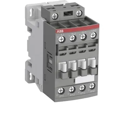
1SBL131001R4210 ABB: The AFC09-30-10-42 is a 3-pole - 690 V IEC or 600 V UL contactor with 1 N.O built-in auxiliary contact and Screw terminals, mainly controlling power circuits up to 4 kW / 400 V AC (AC-3) or 5 hp / 480 V AC UL and 25 A (AC-1) or 25 A UL general use. Within the AF platform, AFC contactors offer an optimized operating time for AC controlled applications with electromagnetic coil (control voltage : 230 ... 240 V AC 50 Hz / 277 V AC 60 Hz). AFC contactors have a block type design and can be easily extended with add-on auxiliary contact blocks and a wide range of additionnal accessories.
Minimum Order Quantity
1 piece
Customs Tariff Number
85364900
Data Sheet, Technical Information
1SBC100219C0201 AFC contactors for AC control applications_Catalog PDF
Instructions and Manuals
Installation instructions AF(C)09...38(Z)(B) Contactors, NF(C)(Z)(B)22...80E Contactor relays and CA4, CAL4, CAT4, CC4, LDC4 Accessories
Instructions and Manuals (Part 2)
Contactors and Overload relays guide
Product Net Width
45 mm
Product Net Depth / Length
77 mm
Product Net Height
86 mm
Product Net Weight
0.298 kg
Number of Main Contacts NO
3
Number of Main Contacts NC
0
Number of Auxiliary Contacts NO
1
Number of Auxiliary Contacts NC
0
Number of Poles
3P
Standards
IEC/EN 60947-1, IEC/EN 60947-4-1, UL 60947-4-1, CSA C22.2 No. 60947-4-1, UL 60335-2-40 LZGH2 A2L
Rated Operational Voltage
Auxiliary Circuit 690 V | Main Circuit 690 V
Rated Frequency (f)
Auxiliary Circuit 50 / 60 Hz | Main Circuit 50 / 60 Hz
Conventional Free-air Thermal Current (Ith)
acc. to IEC 60947-4-1, Open Contactors Θ = 40 °C 35 A | acc. to IEC 60947-5-1, Θ = 40 °C 16 A
Rated Operational Current AC-1 (Ie)
(690 V) 40 °C 25 A | (690 V) 60 °C 25 A | (690 V) 70 °C 22 A
Rated Operational Current AC-3 (Ie)
(415 V) 60 °C 9 A | (440 V) 60 °C 9 A | (500 V) 60 °C 9.5 A | (690 V) 60 °C 7 A | (380 / 400 V) 60 °C 9 A | (220 / 230 / 240 V) 60 °C 9 A
Rated Operational Current AC-3e (Ie)
(415 V) 60 °C 9 A | (440 V) 60 °C 9 A | (500 V) 60 °C 9.5 A | (690 V) 60 °C 7 A | (380 / 400 V) 60 °C 9 A | (220 / 230 / 240 V) 60 °C 9 A
Rated Operational Current AC-15 (Ie)
(500 V) NC 2 | (500 V) 2 A | (690 V) 2 A | (24 / 127 V) 6 A | (220 / 240 V) 4 A | (400 / 440 V) 3 A
Rated Operational Current DC-13 (Ie)
(24 V) 6 A / 144 W | (48 V) 2.8 A / 134 W | (72 V) 1 A / 72 W | (110 V) 0.55 A / 60 W | (125 V) 0.55 A / 69 W | (220 V) 0.27 A / 60 W | (250 V) 0.27 A / 68 W | (400 V) 0.15 A / 60 W | (500 V) 0.13 A / 65 W | (600 V) 0.1 A / 60 W
Rated Operational Power AC-3 (Pe)
(415 V) 4 kW | (440 V) 4 kW | (500 V) 5.5 kW | (690 V) 5.5 kW | (380 / 400 V) 4 kW | (220 / 230 / 240 V) 2.2 kW
Rated Operational Power AC-3e (Pe)
(415 V) 4 kW | (440 V) 4 kW | (500 V) 5.5 kW | (690 V) 5.5 kW | (380 / 400 V) 4 kW | (220 / 230 / 240 V) 2.2 kW
Rated Operational Power AC-6b (Pe)
(400 / 415 V) 40 °C, 50 / 60 Hz 8.5 kvar | (400 / 415 V) 70 °C, 50 / 60 Hz 7 kvar | (400 / 415 V) 55 °C, 50 / 60 Hz 8.5 kvar | (500 / 550 V), 40 °C, 50 / 60 Hz 10.5 kvar | (500 / 550 V) 55 °C, 50 / 60 Hz 10.5 kvar | (500 / 550 V) 70 °C, 50 / 60 Hz 9 kvar | (690 V) 40 °C, 50 / 60 Hz 14.5 kvar | (690 V) 55 °C, 50 / 60 Hz 14.5 kvar | (690 V) 70 °C, 50 / 60 Hz 12 kvar
Rated Short-time Withstand Current Low Voltage (Icw)
at 40 °C Ambient Temp, in Free Air, from a Cold State 10 s 150 A | at 40 °C Ambient Temp, in Free Air, from a Cold State 15 min 35 A | at 40 °C Ambient Temp, in Free Air, from a Cold State 1 min 60 A | at 40 °C Ambient Temp, in Free Air, from a Cold State 1 s 300 A | at 40 °C Ambient Temp, in Free Air, from a Cold State 30 s 80 A | for 0.1 s 140 A | for 1 s 100 A
Maximum Breaking Capacity
cos phi=0.45 (cos phi=0.35 for Ie > 100 A) at 440 V 250 A | cos phi=0.45 (cos phi=0.35 for Ie > 100 A) at 690 V 106 A
Rated Insulation Voltage (Ui)
acc. to IEC 60947-4-1 and VDE 0110 (Gr. C) 690 V | acc. to UL/CSA 600 V
Maximum Electrical Switching Frequency
(AC-1) 600 cycles per hour | (AC-15) 1200 cycles per hour | (AC-2 / AC-4) 300 cycles per hour | (AC-3) 1200 cycles per hour | (DC-13) 900 cycles per hour
Maximum Mechanical Switching Frequency
3600 cycles per hour
Rated Control Circuit Voltage (Uc)
50 Hz 230 ... 240 V | 60 Hz 277 V
Coil Consumption
Average Holding Value 50 / 60 Hz 8 V·A | Average Pull-in Value 50 Hz 70 V·A | Average Pull-in Value 60 Hz 66 V·A
Power Loss
at Rated Operating Conditions AC-1 per Pole 0.8 W | at Rated Operating Conditions AC-3 per Pole 0.1 W
Operate Time
Between Coil De-energization and NC Contact Closing 9 ... 20 ms | Between Coil De-energization and NO Contact Opening 4 ... 18 ms | Between Coil Energization and NC Contact Opening 7 ... 21 ms | Between Coil Energization and NO Contact Closing 10 ... 26 ms
Mounting on DIN Rail
TH35-15 (35 x 15 mm Mounting Rail) acc. to IEC 60715 | TH35-7.5 (35 x 7.5 mm Mounting Rail) acc. to IEC 60715
Mounting by Screws (not supplied)
2 x M4 screws placed diagonally
Connecting Capacity Main Circuit
Flexible with Ferrule 1/2x 0.75 ... 6 mm² | Flexible with Insulated Ferrule 2x 0.75 ... 2.5 mm² | Rigid 1/2x 1 ... 6 mm²
Connecting Capacity Auxiliary Circuit
Flexible with Ferrule 1/2x 0.75 ... 2.5 mm² | Flexible with Insulated Ferrule 1x 0.75 ... 2.5 mm² | Flexible with Insulated Ferrule 2x 0.75 ... 1.5 mm² | Rigid 1/2x 1 ... 2.5 mm²
Connecting Capacity Control Circuit
Flexible with Ferrule 1/2x 0.75 ... 2.5 mm² | Flexible with Insulated Ferrule 1x 0.75 ... 2.5 mm² | Flexible with Insulated Ferrule 2x 0.75 ... 1.5 mm² | Rigid 1/2x 1 ... 2.5 mm²
Wire Stripping Length
Auxiliary Circuit 10 mm | Control Circuit 10 mm | Main Circuit 10 mm
Degree of Protection
acc. to IEC 60529, IEC 60947-1, EN 60529 Auxiliary Terminals IP20 | acc. to IEC 60529, IEC 60947-1, EN 60529 Coil Terminals IP20 | acc. to IEC 60529, IEC 60947-1, EN 60529 Main Terminals IP20
Tightening Torque
Auxiliary Circuit 1.2 N·m | Control Circuit 1.2 N·m | Main Circuit 1.5 N·m
Terminal Type
Screw Terminals
Product Name
Block Contactor
NEMA Size
00
Continuous Current Rating NEMA
9 A
Horsepower Rating NEMA
(115 V AC) Single Phase 1/3 Hp | (200 V AC) Three Phase 1-1/2 Hp | (230 V AC) Single Phase 1 Hp | (230 V AC) Three Phase 1-1/2 Hp | (460 V AC) Three Phase 2 Hp | (575 V AC) Three Phase 2 Hp
Maximum Operating Voltage UL/CSA
Main Circuit 600 V
General Use Rating UL/CSA
(600 V AC) 25 A
Horsepower Rating UL/CSA
(120 V AC) Single Phase 3/4 hp | (200 ... 208 V AC) Three Phase 2 hp | (220 ... 240 V AC) Three Phase 2 hp | (240 V AC) Single Phase 1-1/2 hp | (440 ... 480 V AC) Three Phase 5 hp | (550 ... 600 V AC) Three Phase 7-1/2 hp
Tightening Torque UL/CSA
Auxiliary Circuit 11 in·lb | Control Circuit 11 in·lb | Main Circuit 13 in·lb
Full Load Amps Motor Use
(120 V AC) Single Phase 13.8 A | (200 ... 208 V AC) Three Phase 7.8 A | (220 ... 240 V AC) Three Phase 6.8 A | (240 V AC) Single Phase 10 A | (440 ... 480 V AC) Three Phase 7.6 A | (550 ... 600 V AC) Three Phase 9 A
Ambient Air Temperature
Close to Contactor without Thermal O/L Relay -40 ... 70 °C | Close to Contactor for Storage -60 ... +80 °C | Near Contactor for Operation in Free Air (0.85 ... 1.1 Uc) -40 ... +60 °C | Near Contactor for Operation in Free Air (Uc) -40 ... 70 °C
Climatic Withstand
Category B according to IEC 60947-1 Annex Q
Maximum Operating Altitude Permissible
Without Derating 3000 m
Resistance to Shock acc. to IEC 60068-2-27
Closed, Shock Direction: B1 25 g | Open, Shock Direction: B1 5 g | Shock Direction: A 30 g | Shock Direction: B2 15 g | Shock Direction: C1 25 g | Shock Direction: C2 25 g
Resistance to Vibrations
4g Closed Position & 2g Open position 5 ... 300 Hz
Pollution Degree
3
REACH Declaration
REACH - Letter of Confirmation for block contactors, contactor relays, installation contactors, mini contactors, mini contactor relays, thermal overload relays, electronic overload relays and related accessories
RoHS Information
RoHS II declaration for block contactors, installation contactors, mini contactors, mini contactor relays, thermal overload relays, electronic overload relays and related accessories
RoHS Status
Following EU Directive 2011/65/EU and Amendment 2015/863 July 22, 2019
Toxic Substances Control Act - TSCA
Toxic Substances Control Act (TSCA) declaration for Contactors
WEEE B2C / B2B
Business To Business
WEEE Category
5. Small Equipment (No External Dimension More Than 50 cm)
A2L Certificate – UL
UL-US A2L LZGH2 Certificate of Compliance AFC09 ... AFC38 3-pole contactors with screw terminals - UL 60335-2-40 Household and Similar Electrical Appliances - Safety - Part 2-40: Particular Requirements for Electrical Heat Pumps, Air-Conditioners and Dehumidifiers | UL-CA A2L LZGH2 Certificate of Compliance AFC09 ... AFC38 3-pole contactors with screw terminals - CSA C22.2 No. 60335-2-40 Household and Similar Electrical Appliances - Safety - Part 2-40: Particular Requirements for Electrical Heat Pumps, Air-Conditioners and Dehumidifiers
BV Certificate
BV Certificate AF(C)09...AF(C)38 3-pole and 4-pole contactors with screw and Push-in Spring terminals
CB Certificate
CB Certificate AFC09, AFC12, AFC16 3 or 4-pole contactors
Declaration of Conformity - CCC
CCC Declaration of Conformity, Contactor, AF*09, AF*12, AF*16, Made in France
Declaration of Conformity - CE
EU Declaration of Conformity AFC09..(K) ... AFC96 3-pole Contactors
Declaration of Conformity - UKCA
UK Declaration of Conformity AFC09..(K) ... AFC96 3-pole Contactors
DNV Certificate
DNV Certificate AFC09...96 3-pole & AFC09...80 4-pole contactors with screw, push-in terminals
RINA Certificate
Rina Certificate for AFC09...AFC96 3 pole and 4 pole contactors, NFC relays ,screw and spring terminals
UL Certificate
UL-Certificate of Compliance AFC09 ... AFC38 3-pole contactors
Package Level 1 Units
box 1 piece
Package Level 1 Width
87 mm
Package Level 1 Depth / Length
79 mm
Package Level 1 Height
47 mm
Package Level 1 Gross Weight
0.323 kg
Package Level 1 EAN
3471523022850
Object Classification Code
Q
ETIM 7
EC000066 - Power contactor, AC switching
ETIM 8
EC000066 - Power contactor, AC switching
ETIM 9
EC000066 - Power contactor, AC switching
eClass
V11.0 : 27371003
UNSPSC
39121529
IDEA Granular Category Code (IGCC)
4755 >> Contactors
Feature → The block contactor provides three main normally open contacts (3 NO) and a built-in single NO auxiliary contact, enabling compact motor control in a single device. Business Impact → This configuration supports reliable switching for AC-3 motor loads with a clear path for expansion using add-on auxiliary blocks, reducing panel complexity and spare parts needs. Application → Ideal for conveyors, pumps, and fans where space is at a premium and future expansion may be required. Feature → Coil control voltage options provide flexibility with 50 Hz 230–240 V or 60 Hz 277 V, matching common industrial control voltages. Business Impact → Simplifies integration with existing control circuits and minimizes stocking of multiple coil variants. Application → Suitable for global installations with mixed supply grids in process lines and packaging equipment. Feature → High insulation and voltage ratings support safe operation up to 690 V main circuit, with AC-3 and AC-1 performance suitable for small to mid-size motors. Business Impact → Enables reliable motor starting and reduced wear on contact surfaces, improving uptime and energy efficiency. Application → Presses, grinders, and mixer lines in food, chemical, and metalworking sectors. Feature → Durable mounting and connections include DIN rail TH35-15 compatibility and screw terminals with defined tightening torques. Business Impact → Faster, safer installation and maintenance with repeatable torque specs, lowering commissioning time and field service costs. Application → Control cabinets in OEM automation cells and retrofit projects. Feature → Measured power loss and switching characteristics ensure predictable performance: coil hold and pull-in values, 9–26 ms operate times, and up to 3600 mechanical cycles per hour. Business Impact → Improves reliability in high-frequency switching applications and supports life-cycle cost reduction. Application → Pump drive and feeder systems with frequent on/off cycles.
Get a Quick Quote for a ABB 1SBL131001R4210
Chat with us on WhatsApp - fast responses guaranteed
Need to speak with someone? We'll call you back within 2 hours during business hours
Interested in ABB 1SBL131001R4210?
Enquire Now
FAQs
Install the 1SBL131001R4210 on a TH35-15 DIN rail, aligning the mounting feet and snapping it into place. Use the screw terminals for the main and auxiliary circuits, tighten per the specified torques, and connect the coil to 230–240 V AC or 277 V AC as required. This standard mounting method minimizes wiring errors and speeds up commissioning in control cabinets.
For AC-3 operation at 690 V, the rated operational current Ie is 7 A, with ratings adapting at other voltages (e.g., 9 A at lower main voltages like 380–400 V). This makes the device suitable for small to mid-size motor control tasks while maintaining safe overload margins.
Yes. It supports AC-3 loads with up to 5.5 kW at 415–690 V (and 2.2 kW at 220–240 V), plus a 3 NO main contact arrangement and an additional NO auxiliary contact. Combined with a robust coil voltage range, it is well-suited for motor starters in pump and conveyor applications while enabling simple expansion with add-on contact blocks.
The device complies with IEC/EN 60947-1 and 60947-4-1, has UL/CSA listings, and supports CE compatibility. Additional certifications referenced include UL A2L listings and related declarations (e.g., CE/UKCA) documented in ABB’s certificates and product declarations for contactors in this family.
The integrated auxiliary contact and modular block design reduce wiring complexity and spare parts, lowering maintenance time. DIN rail mounting and standardized torque specs speed installations, while low power loss (0.8 W AC-1 per pole, 0.1 W AC-3 per pole) improves overall energy efficiency and long-term operating costs in routine switching cycles.