ABB 1SBL131001R8810 Block Contactor - UL/CSA Listed
Part Number: 1SBL131001R8810
Quick Summary
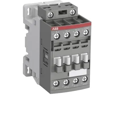
ABB 1SBL131001R8810 block contactor is a 3-pole control device designed for AC control applications with a 230–240 V coil (50 Hz) or 240–260 V (60 Hz). In demanding cabinet environments, engineers need compact, reliable switching with easy expansion options; this unit delivers with a built-in 1 NO auxiliary contact and screw terminals. It conforms to key standards such as IEC/EN 60947-1, IEC/EN 60947-4-1, UL 60947-4-1, and CSA C22.2 No. 60947-4-1, along with CE/UKCA declarations, ensuring global compliance for equipment in both industrial and commercial settings. By offering a block design that accepts add-on auxiliary blocks and a wide accessory range, it reduces engineering time while improving uptime and safety in motor control and general switching duties.
Product Information
Extended Description
1SBL131001R8810 ABB: The AFC09-30-10-88 is a 3-pole - 690 V IEC or 600 V UL contactor with 1 N.O built-in auxiliary contact and Screw terminals, mainly controlling power circuits up to 4 kW / 400 V AC (AC-3) or 5 hp / 480 V AC UL and 25 A (AC-1) or 25 A UL general use. Within the AF platform, AFC contactors offer an optimized operating time for AC controlled applications with electromagnetic coil (control voltage : 230 ... 240 V AC 50 Hz / 240 ... 260 V AC 60 Hz). AFC contactors have a block type design and can be easily extended with add-on auxiliary contact blocks and a wide range of additionnal accessories.
Minimum Order Quantity
1 piece
Customs Tariff Number
85364900
Data Sheet, Technical Information
1SBC100219C0201 AFC contactors for AC control applications_Catalog PDF
Instructions and Manuals
Installation instructions AF(C)09...38(Z)(B) Contactors, NF(C)(Z)(B)22...80E Contactor relays and CA4, CAL4, CAT4, CC4, LDC4 Accessories
Instructions and Manuals (Part 2)
Contactors and Overload relays guide
CAD Dimensional Drawing
Information - 2D and 3D files for CAD systems
Product Net Width
45 mm
Product Net Depth / Length
77 mm
Product Net Height
86 mm
Product Net Weight
0.303 kg
Number of Main Contacts NO
3
Number of Main Contacts NC
0
Number of Auxiliary Contacts NO
1
Number of Auxiliary Contacts NC
0
Number of Poles
3P
Standards
IEC/EN 60947-1, IEC/EN 60947-4-1, UL 60947-4-1, CSA C22.2 No. 60947-4-1, UL 60335-2-40 LZGH2 A2L
Rated Operational Voltage
Auxiliary Circuit 690 V | Main Circuit 690 V
Rated Frequency (f)
Auxiliary Circuit 50 / 60 Hz | Control Circuit 50 / 60 Hz | Main Circuit 50 / 60 Hz
Conventional Free-air Thermal Current (Ith)
acc. to IEC 60947-4-1, Open Contactors Θ = 40 °C 35 A | acc. to IEC 60947-5-1, Θ = 40 °C 16 A
Rated Operational Current AC-1 (Ie)
(690 V) 40 °C 25 A | (690 V) 60 °C 25 A | (690 V) 70 °C 22 A
Rated Operational Current AC-3 (Ie)
(415 V) 60 °C 9 A | (440 V) 60 °C 9 A | (500 V) 60 °C 9.5 A | (690 V) 60 °C 7 A | (380 / 400 V) 60 °C 9 A | (220 / 230 / 240 V) 60 °C 9 A
Rated Operational Current AC-3e (Ie)
(415 V) 60 °C 9 A | (440 V) 60 °C 9 A | (500 V) 60 °C 9.5 A | (690 V) 60 °C 7 A | (380 / 400 V) 60 °C 9 A | (220 / 230 / 240 V) 60 °C 9 A
Rated Operational Current AC-15 (Ie)
(500 V) 2 A | (690 V) 2 A | (24 / 127 V) 6 A | (220 / 240 V) 4 A | (400 / 440 V) 3 A
Rated Operational Current DC-1 (Ie)
(110 V) 1-Pole, 40 °C 10 A | (110 V) 1-Pole, 60 °C 10 A | (110 V) 1-Pole, 70 °C 10 A | (110 V) 2 Poles in Series, 40 °C 25 A | (110 V) 2 Poles in Series, 60 °C 25 A | (110 V) 2 Poles in Series, 70 °C 22 A | (110 V) 3 Poles in Series, 40 °C 25 A | (110 V) 3 Poles in Series, 60 °C 25 A | (110 V) 3 Poles in Series, 70 °C 22 A | (220 V) 2 Poles in Series, 40 °C 10 A | (220 V) 2 Poles in Series, 60 °C 10 A | (220 V) 2 Poles in Series, 70 °C 10 A | (220 V) 3 Poles in Series, 40 °C 25 A | (220 V) 3 Poles in Series, 60 °C 25 A | (220 V) 3 Poles in Series, 70 °C 22 A | (72 V) 1-Pole, 40 °C 25 A | (72 V) 1-Pole, 60 °C 25 A | (72 V) 1-Pole, 70 °C 22 A | (72 V) 2 Poles in Series, 40 °C 25 A | (72 V) 2 Poles in Series, 60 °C 25 A | (72 V) 2 Poles in Series, 70 °C 22 A | (72 V) 3 Poles in Series, 40 °C 25 A | (72 V) 3 Poles in Series, 60 °C 25 A | (72 V) 3 Poles in Series, 70 °C 22 A
Rated Operational Current DC-3 (Ie)
(110 V) 1-Pole, 40 °C 6 A | (110 V) 1-Pole, 60 °C 6 A | (110 V) 1-Pole, 70 °C 6 A | (110 V) 2 Poles in Series, 40 °C 25 A | (110 V) 2 Poles in Series, 60 °C 25 A | (110 V) 2 Poles in Series, 70 °C 22 A | (110 V) 3 Poles in Series, 40 °C 25 A | (110 V) 3 Poles in Series, 60 °C 25 A | (110 V) 3 Poles in Series, 70 °C 22 A | (220 V) 2 Poles in Series, 40 °C 6 A | (220 V) 2 Poles in Series, 60 °C 6 A | (220 V) 2 Poles in Series, 70 °C 6 A | (220 V) 3 Poles in Series, 40 °C 25 A | (220 V) 3 Poles in Series, 60 °C 25 A | (220 V) 3 Poles in Series, 70 °C 22 A | (72 V) 1-Pole, 40 °C 25 A | (72 V) 1-Pole, 60 °C 25 A | (72 V) 1-Pole, 70 °C 22 A | (72 V) 2 Poles in Series, 40 °C 25 A | (72 V) 2 Poles in Series, 60 °C 25 A | (72 V) 2 Poles in Series, 70 °C 22 A | (72 V) 3 Poles in Series, 40 °C 25 A | (72 V) 3 Poles in Series, 60 °C 25 A | (72 V) 3 Poles in Series, 70 °C 22 A
Rated Operational Current DC-5 (Ie)
(110 V) 1-Pole, 40 °C 4 A | (110 V) 1-Pole, 60 °C 4 A | (110 V) 1-Pole, 70 °C 4 A | (110 V) 2 Poles in Series, 40 °C 10 A | (110 V) 2 Poles in Series, 60 °C 10 A | (110 V) 2 Poles in Series, 70 °C 10 A | (110 V) 3 Poles in Series, 40 °C 25 A | (110 V) 3 Poles in Series, 60 °C 25 A | (110 V) 3 Poles in Series, 70 °C 22 A | (220 V) 2 Poles in Series, 40 °C 4 A | (220 V) 2 Poles in Series, 60 °C 4 A | (220 V) 2 Poles in Series, 70 °C 4 A | (220 V) 3 Poles in Series, 40 °C 9 A | (220 V) 3 Poles in Series, 60 °C 9 A | (220 V) 3 Poles in Series, 70 °C 9 A | (72 V) 1-Pole, 40 °C 9 A | (72 V) 1-Pole, 60 °C 9 A | (72 V) 1-Pole, 70 °C 9 A | (72 V) 2 Poles in Series, 40 °C 25 A | (72 V) 2 Poles in Series, 60 °C 25 A | (72 V) 2 Poles in Series, 70 °C 22 A | (72 V) 3 Poles in Series, 40 °C 25 A | (72 V) 3 Poles in Series, 60 °C 25 A | (72 V) 3 Poles in Series, 70 °C 22 A
Rated Operational Current DC-13 (Ie)
(24 V) 6 A / 144 W | (48 V) 2.8 A / 134 W | (72 V) 1 A / 72 W | (110 V) 0.55 A / 60 W | (125 V) 0.55 A / 69 W | (220 V) 0.27 A / 60 W | (250 V) 0.27 A / 68 W | (400 V) 0.15 A / 60 W | (500 V) 0.13 A / 65 W | (600 V) 0.1 A / 60 W
Rated Operational Power AC-3 (Pe)
(415 V) 4 kW | (440 V) 4 kW | (500 V) 5.5 kW | (690 V) 5.5 kW | (380 / 400 V) 4 kW | (220 / 230 / 240 V) 2.2 kW
Rated Operational Power AC-3e (Pe)
(415 V) 4 kW | (440 V) 4 kW | (500 V) 5.5 kW | (690 V) 5.5 kW | (380 / 400 V) 4 kW | (220 / 230 / 240 V) 2.2 kW
Rated Operational Power AC-6b (Pe)
(400 / 415 V) 40 °C, 50 / 60 Hz 8.5 kvar | (400 / 415 V) 70 °C, 50 / 60 Hz 7 kvar | (400 / 415 V) 55 °C, 50 / 60 Hz 8.5 kvar | (500 / 550 V), 40 °C, 50 / 60 Hz 10.5 kvar | (500 / 550 V) 55 °C, 50 / 60 Hz 10.5 kvar | (500 / 550 V) 70 °C, 50 / 60 Hz 9 kvar | (690 V) 40 °C, 50 / 60 Hz 14.5 kvar | (690 V) 55 °C, 50 / 60 Hz 14.5 kvar | (690 V) 70 °C, 50 / 60 Hz 12 kvar
Rated Short-time Withstand Current Low Voltage (Icw)
at 40 °C Ambient Temp, in Free Air, from a Cold State 10 s 150 A | at 40 °C Ambient Temp, in Free Air, from a Cold State 15 min 35 A | at 40 °C Ambient Temp, in Free Air, from a Cold State 1 min 60 A | at 40 °C Ambient Temp, in Free Air, from a Cold State 1 s 300 A | at 40 °C Ambient Temp, in Free Air, from a Cold State 30 s 80 A | for 0.1 s 140 A | for 1 s 100 A
Maximum Breaking Capacity
cos phi=0.45 (cos phi=0.35 for Ie > 100 A) at 440 V 250 A | cos phi=0.45 (cos phi=0.35 for Ie > 100 A) at 690 V 106 A
Rated Insulation Voltage (Ui)
acc. to IEC 60947-4-1 690 V | acc. to IEC 60947-5-1 690 V | acc. to UL/CSA 600 V
Rated Impulse Withstand Voltage (Uimp)
6 kV
Maximum Electrical Switching Frequency
(AC-1) 600 cycles per hour | (AC-15) 1200 cycles per hour | (AC-2 / AC-4) 300 cycles per hour | (AC-3) 1200 cycles per hour | (DC-13) 900 cycles per hour
Maximum Mechanical Switching Frequency
3600 cycles per hour
Rated Control Circuit Voltage (Uc)
50 Hz 230 ... 240 V | 60 Hz 240 ... 260 V
Coil Consumption
Average Holding Value 50 / 60 Hz 8 V·A | Average Pull-in Value 50 Hz 70 V·A | Average Pull-in Value 60 Hz 66 V·A
Power Loss
at 6 A per Pole 0.1 W | at Rated Operating Conditions AC-1 per Pole 0.8 W | at Rated Operating Conditions AC-3 per Pole 0.1 W
Operate Time
Between Coil De-energization and NC Contact Closing 9 ... 20 ms | Between Coil De-energization and NO Contact Opening 4 ... 18 ms | Between Coil Energization and NC Contact Opening 7 ... 21 ms | Between Coil Energization and NO Contact Closing 10 ... 26 ms
Mounting on DIN Rail
TH35-15 (35 x 15 mm Mounting Rail) acc. to IEC 60715 | TH35-7.5 (35 x 7.5 mm Mounting Rail) acc. to IEC 60715
Mounting by Screws (not supplied)
2 x M4 screws placed diagonally
Connecting Capacity Main Circuit
Flexible with Ferrule 1/2x 0.75 ... 6 mm² | Flexible with Insulated Ferrule 1x 0.75 ... 4 mm² | Flexible with Insulated Ferrule 2x 0.75 ... 2.5 mm² | Rigid Solid 1/2x 1 ... 4 mm² | Rigid Stranded 1/2x 1 ... 6 mm²
Connecting Capacity Auxiliary Circuit
Flexible with Ferrule 1/2x 0.75 ... 2.5 mm² | Flexible with Insulated Ferrule 1x 0.75 ... 2.5 mm² | Flexible with Insulated Ferrule 2x 0.75 ... 1.5 mm² | Rigid Solid 1/2x 1 ... 2.5 mm² | Rigid Stranded 1/2x 1 ... 2.5 mm²
Connecting Capacity Control Circuit
Flexible with Ferrule 1/2x 0.75 ... 2.5 mm² | Flexible with Insulated Ferrule 1x 0.75 ... 2.5 mm² | Flexible with Insulated Ferrule 2x 0.75 ... 1.5 mm² | Rigid Solid 1/2x 1 ... 2.5 mm² | Rigid Stranded 1/2x 1 ... 2.5 mm²
Wire Stripping Length
Auxiliary Circuit 10 mm | Control Circuit 10 mm | Main Circuit 10 mm
Degree of Protection
acc. to IEC 60529, IEC 60947-1, EN 60529 Auxiliary Terminals IP20 | acc. to IEC 60529, IEC 60947-1, EN 60529 Coil Terminals IP20 | acc. to IEC 60529, IEC 60947-1, EN 60529 Main Terminals IP20
Tightening Torque
Auxiliary Circuit 1.2 N·m | Control Circuit 1.2 N·m | Main Circuit 1.5 N·m
Terminal Type
Screw Terminals
Product Name
Block Contactor
NEMA Size
00
Continuous Current Rating NEMA
9 A
Horsepower Rating NEMA
(115 V AC) Single Phase 1/3 Hp | (200 V AC) Three Phase 1-1/2 Hp | (230 V AC) Single Phase 1 Hp | (230 V AC) Three Phase 1-1/2 Hp | (460 V AC) Three Phase 2 Hp | (575 V AC) Three Phase 2 Hp
Maximum Operating Voltage UL/CSA
Main Circuit 600 V
General Use Rating UL/CSA
(600 V AC) 25 A
Horsepower Rating UL/CSA
(120 V AC) Single Phase 3/4 hp | (200 ... 208 V AC) Three Phase 2 hp | (220 ... 240 V AC) Three Phase 2 hp | (240 V AC) Single Phase 1-1/2 hp | (440 ... 480 V AC) Three Phase 5 hp | (550 ... 600 V AC) Three Phase 7-1/2 hp
Connecting Capacity Main Circuit UL/CSA
Rigid Solid 1/2x 16-10 AWG | Rigid Stranded 1/2x 16-10 AWG
Connecting Capacity Auxiliary Circuit UL/CSA
Rigid Solid 1/2x 18-14 AWG | Rigid Stranded 1/2x 18-14 AWG
Connecting Capacity Control Circuit UL/CSA
Rigid Solid 1/2x 18-14 AWG | Rigid Stranded 1/2x 18-14 AWG
Tightening Torque UL/CSA
Auxiliary Circuit 11 in·lb | Control Circuit 11 in·lb | Main Circuit 13 in·lb
Full Load Amps Motor Use
(120 V AC) Single Phase 13.8 A | (200 ... 208 V AC) Three Phase 7.8 A | (220 ... 240 V AC) Three Phase 6.8 A | (240 V AC) Single Phase 10 A | (440 ... 480 V AC) Three Phase 7.6 A | (550 ... 600 V AC) Three Phase 9 A
Ambient Air Temperature
Close to Contactor Fitted with Thermal O/L Relay -25 ... 60 °C | Close to Contactor without Thermal O/L Relay -40 ... 70 °C | Close to Contactor without Thermal O/L Relay (0.85 ... 1.1 Uc) -40 ... 60 °C | Close to Contactor without Thermal O/L Relay (Uc) -40 ... 70 °C | Close to Contactor for Storage -60 ... +80 °C
Climatic Withstand
Category B according to IEC 60947-1 Annex Q
Maximum Operating Altitude Permissible
Without Derating 3000 m
Resistance to Shock acc. to IEC 60068-2-27
Closed, Shock Direction: B1 25 g | Open, Shock Direction: B1 5 g | Shock Direction: A 30 g | Shock Direction: B2 15 g | Shock Direction: C1 25 g | Shock Direction: C2 25 g
Resistance to Vibrations
4g Closed Position & 2g Open position 5 ... 300 Hz
Pollution Degree
3
Conflict Minerals Reporting Template (CMRT)
CMRT - Conflict Minerals Reporting Template
REACH Declaration
REACH - Letter of Confirmation for block contactors, contactor relays, installation contactors, mini contactors, mini contactor relays, thermal overload relays, electronic overload relays and related accessories
RoHS Information
RoHS II declaration for block contactors, installation contactors, mini contactors, mini contactor relays, thermal overload relays, electronic overload relays and related accessories
RoHS Status
Following EU Directive 2011/65/EU and Amendment 2015/863 July 22, 2019
Toxic Substances Control Act - TSCA
Toxic Substances Control Act (TSCA) declaration for Contactors
WEEE B2C / B2B
Business To Business
WEEE Category
5. Small Equipment (No External Dimension More Than 50 cm)
A2L Certificate – UL
UL-US A2L LZGH2 Certificate of Compliance AFC09 ... AFC38 3-pole contactors with screw terminals - UL 60335-2-40 Household and Similar Electrical Appliances - Safety - Part 2-40: Particular Requirements for Electrical Heat Pumps, Air-Conditioners and Dehumidifiers | UL-CA A2L LZGH2 Certificate of Compliance AFC09 ... AFC38 3-pole contactors with screw terminals - CSA C22.2 No. 60335-2-40 Household and Similar Electrical Appliances - Safety - Part 2-40: Particular Requirements for Electrical Heat Pumps, Air-Conditioners and Dehumidifiers
BV Certificate
BV Certificate AF(C)09...AF(C)38 3-pole and 4-pole contactors with screw and Push-in Spring terminals
CB Certificate
CB Certificate AFC09, AFC12, AFC16 3 or 4-pole contactors
CCS Certificate
CCS Certificate of AFC09 ... AFC96 , AX09-AX370 contactors
CQC Certificate
CQC Certificate AF(C)09, AF(C)12, AF(C)16, AF09(Z)B, AF12(Z)B, AF16(Z)B 3 and 4-pole contactors, AFS09, AFS12, AFS16 safety contactors
Declaration of Conformity - CCC
CCC Declaration of Conformity, Contactor, AF*09, AF*12, AF*16, Made in France
Declaration of Conformity - CE
EU Declaration of Conformity AFC09..(K) ... AFC96 3-pole Contactors
Declaration of Conformity - UKCA
UK Declaration of Conformity AFC09..(K) ... AFC96 3-pole Contactors
DNV Certificate
DNV Certificate AFC09...96 3-pole & AFC09...80 4-pole contactors with screw, push-in terminals
RINA Certificate
Rina Certificate for AFC09...AFC96 3 pole and 4 pole contactors, NFC relays ,screw and spring terminals
UL Certificate
UL-Certificate of Compliance AFC09 ... AFC38 3-pole contactors
Package Level 1 Units
box 1 piece
Package Level 1 Width
87 mm
Package Level 1 Depth / Length
79 mm
Package Level 1 Height
47 mm
Package Level 1 Gross Weight
0.324 kg
Package Level 1 EAN
3471523013919
Package Level 3 Units
1296 piece
Object Classification Code
Q
ETIM 7
EC000066 - Power contactor, AC switching
ETIM 8
EC000066 - Power contactor, AC switching
ETIM 9
EC000066 - Power contactor, AC switching
eClass
V11.0 : 27371003
UNSPSC
39121529
IDEA Granular Category Code (IGCC)
4755 >> Contactors
Feature: 3-pole design with 1 NO auxiliary contact. Business Impact: Simplifies wiring and allows monitoring or interlocking of the main circuit without a separate relay. Application: Ideal for AC-3 motor control of small to mid-size loads in compact MCCs. Scenario: Reduces panel footprint while preserving control versatility in automation cells. Feature: Coil voltage 230–240 V AC at 50 Hz or 240–260 V AC at 60 Hz. Business Impact: Enables direct compatibility with common control circuits in Europe and North America without adapters. Application: Suitable for standardized control cabinets powering 3-phase motors up to 4 kW. Feature: Rated Operational Voltage and Current (690 V main circuit; various Ie values). Business Impact: Supports high-voltage mains while preserving reliable switching performance and lifecycle. Application: Automotive, packaging, and process lines requiring robust AC-3 switching at 400–690 V. Feature: Block type design with extendable accessories. Business Impact: Facilitates future expansion via auxiliary contact blocks and accessories, reducing replacement needs. Application: Scales with increasing automation demands in legacy lines. Feature: DIN rail mounting options TH35-15 and TH35-7.5; Screw terminals. Business Impact: Quick, secure installation with flexible cabinet layouts and straightforward field wiring. Application: Common in control panels for machine builders and system integrators. Feature: IP20 protection on terminals; Tightening torques specified. Business Impact: Enhances safety in dusty or humid industrial environments while ensuring reliable terminations. Application: Suitable for standard indoor electrical enclosures. Feature: Power loss and operate time data (0.8 W per pole AC-1; 9–26 ms operate time). Business Impact: Predictable coil behavior improves PLC/relay timing coordination and reduces nuisance tripping. Application: Precision sequencing in conveyor, pump, and fan control. Feature: Compliance and documentation suite (CE, UKCA, UL/CSA, WEEE, ROHS). Business Impact: Streamlines regulatory approval and lifecycle management across regions. Application: Global deployment with consistent safety and environmental conformity.
Get a Quick Quote for a ABB 1SBL131001R8810
Chat with us on WhatsApp - fast responses guaranteed
Need to speak with someone? We'll call you back within 2 hours during business hours
Interested in ABB 1SBL131001R8810?
Enquire Now
FAQs
This 3-pole block contactor supports DIN rail mounting on TH35-15 or TH35-7.5 rails and can also be screwed to a panel with two M4 screws. The screw-terminal design simplifies field wiring, while the compact 45 mm x 77 mm footprint fits tight panel layouts.
For AC-3 at 690 V, the rated operational current is 7 A (60 °C). In AC-3e configurations, the device maintains similar current handling up to the specified voltage ranges. This makes it suitable for motor loads in the 2–9 A range depending on voltage and ambient temperature.
Yes. The AFC09 family supports rated operational power in AC-3 up to around 4 kW for voltages in the 380–690 V range, depending on enclosure, ambient temperature, and duty cycle. At 690 V, this enables reliable switching of typical small to mid-size motors in automation circuits.
The AFC09 family complies with IEC/EN 60947-1, IEC/EN 60947-4-1, UL 60947-4-1, and CSA C22.2 No. 60947-4-1, with CE and UKCA declarations. Additional certifications include UL 60335-2-40 considerations and related safety validations for household and industrial appliances in specified configurations.
Key ROI drivers include low coil power loss (0.8 W per pole at rated AC-1 conditions), compact footprint reducing panel real estate, and DIN-rail compatibility enabling quick swaps or expansions. The device also supports add-on auxiliary blocks, reducing future wiring and inventory needs while enhancing uptime through reliable, industry-standard switching.