ABB 1SBL131201R8600 Block Contactor - 690 V IEC/UL
Part Number: 1SBL131201R8600
Quick Summary
Block Contactor is a heavy-duty switching device that reliably controls three-phase power circuits in industrial machinery. Engineers often struggle with compact, modular control solutions that meet IEC/UL ratings while delivering long life in harsh environments. This ABB device aligns with IEC/EN 60947-4-1 and UL 60947-4-1 standards and is complemented by CE and UKCA certifications for broad market access. With DIN rail mounting and screw-terminal connections, it enables quick installation and dependable operation in motor control panels, power distribution, and automation cabinets. The combination of compact form factor and robust electrical ratings supports scalable, cost-efficient system design for OEMs and panel builders alike.
Product Information
Extended Description
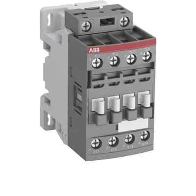
1SBL131201R8600 ABB: The AFC09-40-00-86 is a 4-pole (4 N.O) - 690 V IEC or 600 V UL contactor withScrew terminals, mainly controlling power circuits up to 25 A (IEC AC-1) or 25 A UL general use. Within the AF platform, AFC contactors offer an optimized operating time for AC controlled applications with electromagnetic coil (control voltage : 400 ... 415 V AC 50 Hz / 415 ... 440 V AC 60 Hz). AFC contactors have a block type design and can be easily extended with add-on auxiliary contact blocks and a wide range of additionnal accessories.
Minimum Order Quantity
1 piece
Customs Tariff Number
85364900
Data Sheet, Technical Information
1SBC100219C0201 AFC contactors for AC control applications_Catalog PDF
Instructions and Manuals
Installation instructions AF(C)09...38(Z)(B) Contactors, NF(C)(Z)(B)22...80E Contactor relays and CA4, CAL4, CAT4, CC4, LDC4 Accessories
Instructions and Manuals (Part 2)
Contactors and Overload relays guide
Product Net Width
45 mm
Product Net Depth / Length
77 mm
Product Net Height
86 mm
Product Net Weight
0.298 kg
Number of Main Contacts NO
4
Number of Main Contacts NC
0
Number of Auxiliary Contacts NO
0
Number of Auxiliary Contacts NC
0
Number of Poles
4P
Standards
IEC/EN 60947-1, IEC/EN 60947-4-1, UL 60947-1, UL 60947-4-1, CAN/CSA C22.2 No.60947-1, CAN/CSA C22.2 No.60947-4-1
Rated Operational Voltage
Main Circuit 690 V
Rated Frequency (f)
Auxiliary Circuit 50 / 60 Hz | Main Circuit 50 / 60 Hz
Conventional Free-air Thermal Current (Ith)
acc. to IEC 60947-4-1, Open Contactors Θ = 40 °C 35 A
Rated Operational Current AC-1 (Ie)
(690 V) 40 °C 25 A | (690 V) 60 °C 25 A | (690 V) 70 °C 22 A
Rated Operational Current AC-3 (Ie)
(415 V) 60 °C 9 A | (440 V) 60 °C 9 A | (500 V) 60 °C 9.5 A | (690 V) 60 °C 7 A | (380 / 400 V) 60 °C 9 A | (220 / 230 / 240 V) 60 °C 9 A
Rated Operational Power AC-3 (Pe)
(415 V) 4 kW | (440 V) 4 kW | (500 V) 5.5 kW | (690 V) 5.5 kW | (380 / 400 V) 4 kW | (220 / 230 / 240 V) 2.2 kW
Rated Short-time Withstand Current Low Voltage (Icw)
at 40 °C Ambient Temp, in Free Air, from a Cold State 10 s 150 A | at 40 °C Ambient Temp, in Free Air, from a Cold State 15 min 35 A | at 40 °C Ambient Temp, in Free Air, from a Cold State 1 min 60 A | at 40 °C Ambient Temp, in Free Air, from a Cold State 1 s 300 A | at 40 °C Ambient Temp, in Free Air, from a Cold State 30 s 80 A
Maximum Breaking Capacity
cos phi=0.45 (cos phi=0.35 for Ie > 100 A) at 440 V 250 A | cos phi=0.45 (cos phi=0.35 for Ie > 100 A) at 690 V 106 A
Rated Insulation Voltage (Ui)
acc. to IEC 60947-4-1 and VDE 0110 (Gr. C) 690 V | acc. to UL/CSA 600 V
Rated Impulse Withstand Voltage (Uimp)
6 kV | Auxiliary Circuit 6 kV
Maximum Electrical Switching Frequency
(AC-1) 600 cycles per hour | (AC-15) 0 cycles per hour | (AC-2 / AC-4) 0 cycles per hour | (AC-3) 0 cycles per hour | (DC-13) 0 cycles per hour
Maximum Mechanical Switching Frequency
3600 cycles per hour
Rated Control Circuit Voltage (Uc)
50 Hz 400 ... 415 V | 60 Hz 415 ... 440 V
Coil Consumption
Average Holding Value 50 / 60 Hz 8 V·A | Average Pull-in Value 50 Hz 70 V·A | Average Pull-in Value 60 Hz 66 V·A
Power Loss
at Rated Operating Conditions AC-1 per Pole 0.8 W | at Rated Operating Conditions AC-3 per Pole 0.1 W
Operate Time
Between Coil De-energization and NC Contact Closing 9 ... 20 ms | Between Coil De-energization and NO Contact Opening 4 ... 18 ms | Between Coil Energization and NC Contact Opening 7 ... 21 ms | Between Coil Energization and NO Contact Closing 10 ... 26 ms
Mounting on DIN Rail
TH35-15 (35 x 15 mm Mounting Rail) acc. to IEC 60715 | TH35-7.5 (35 x 7.5 mm Mounting Rail) acc. to IEC 60715
Mounting by Screws (not supplied)
2 x M4 screws placed diagonally
Connecting Capacity Main Circuit
Flexible with Ferrule 1/2x 0.75 ... 6 mm² | Flexible with Insulated Ferrule 1x 0.75 ... 4 mm² | Flexible with Insulated Ferrule 2x 0.75 ... 2.5 mm² | Flexible with Insulated Ferrule 2x 0.75 ... 2.5 mm² | Rigid 1/2x 1 ... 6 mm²
Connecting Capacity Auxiliary Circuit
Flexible with Ferrule 1/2x 0.75 ... 2.5 mm² | Flexible with Insulated Ferrule 1x 0.75 ... 2.5 mm² | Flexible with Insulated Ferrule 2x 0.75 ... 1.5 mm²
Connecting Capacity Control Circuit
Flexible with Ferrule 1/2x 0.75 ... 2.5 mm² | Flexible with Insulated Ferrule 1x 0.75 ... 2.5 mm² | Flexible with Insulated Ferrule 2x 0.75 ... 1.5 mm² | Flexible with Insulated Ferrule 1x 0.75 ... 2.5 mm² | Flexible with Insulated Ferrule 2x 0.75 ... 1.5 mm² | Rigid 1/2x 1 ... 2.5 mm²
Wire Stripping Length
Control Circuit 10 mm | Main Circuit 10 mm
Degree of Protection
acc. to IEC 60529, IEC 60947-1, EN 60529 Coil Terminals IP20 | acc. to IEC 60529, IEC 60947-1, EN 60529 Main Terminals IP20
Tightening Torque
Auxiliary Circuit 1.2 N·m | Control Circuit 1.2 N·m | Main Circuit 1.5 N·m
Terminal Type
Screw Terminals
Product Name
Block Contactor
Maximum Operating Voltage UL/CSA
Main Circuit 600 V
General Use Rating UL/CSA
(600 V AC) 25 A
Tightening Torque UL/CSA
Control Circuit 11 in·lb | Main Circuit 13 in·lb
Ambient Air Temperature
Close to Contactor Fitted with Thermal O/L Relay -25 ... 60 °C | Close to Contactor without Thermal O/L Relay -40 ... 70 °C | Close to Contactor for Storage -60 ... +80 °C | Near Contactor for Operation in Free Air -40 ... 70 °C | Near Contactor for Operation in Free Air (0.85 ... 1.1 Uc) -40 ... +60 °C | Near Contactor for Operation in Free Air (Uc) -40 ... 70 °C
Climatic Withstand
Category B according to IEC 60947-1 Annex Q
Maximum Operating Altitude Permissible
Without Derating 3000 m
Resistance to Shock acc. to IEC 60068-2-27
Closed, Shock Direction: B1 25 g | Open, Shock Direction: B1 5 g | Shock Direction: A 30 g | Shock Direction: B2 15 g | Shock Direction: C1 25 g | Shock Direction: C2 25 g
Resistance to Vibrations
4g Closed Position & 2g Open position 5 ... 300 Hz
Pollution Degree
3
REACH Declaration
REACH - Letter of Confirmation for block contactors, contactor relays, installation contactors, mini contactors, mini contactor relays, thermal overload relays, electronic overload relays and related accessories
RoHS Information
RoHS II declaration for block contactors, installation contactors, mini contactors, mini contactor relays, thermal overload relays, electronic overload relays and related accessories
RoHS Status
Following EU Directive 2011/65/EU and Amendment 2015/863 July 22, 2019
Toxic Substances Control Act - TSCA
Toxic Substances Control Act (TSCA) declaration for Contactors
WEEE B2C / B2B
Business To Business
WEEE Category
5. Small Equipment (No External Dimension More Than 50 cm)
BV Certificate
BV Certificate AF(C)09...AF(C)38 3-pole and 4-pole contactors with screw and Push-in Spring terminals
CB Certificate
CB Certificate AFC09, AFC12, AFC16 3 or 4-pole contactors
CQC Certificate
CQC Certificate AF(C)09, AF(C)12, AF(C)16, AF09(Z)B, AF12(Z)B, AF16(Z)B 3 and 4-pole contactors, AFS09, AFS12, AFS16 safety contactors
Declaration of Conformity - CCC
CCC Declaration of Conformity, Contactor, AF*09, AF*12, AF*16, Made in France
Declaration of Conformity - CE
EU Declaration of Conformity AFC09 ... AFC80 4-pole Contactors
Declaration of Conformity - UKCA
UK Declaration of Conformity AFC09 ... AFC80 4-pole Contactors
DNV Certificate
DNV Certificate AFC09...96 3-pole & AFC09...80 4-pole contactors with screw, push-in terminals
RINA Certificate
Rina Certificate for AFC09...AFC96 3 pole and 4 pole contactors, NFC relays ,screw and spring terminals
UL Certificate
UL-US Certificate of Compliance AFC09 ... AFC38 4-pole contactors | UL-CA Certificate of Compliance AFC09 ... AFC38 4-pole contactors
Package Level 1 Units
box 1 piece
Package Level 1 Width
87 mm
Package Level 1 Depth / Length
79 mm
Package Level 1 Height
47 mm
Package Level 1 Gross Weight
0.321 kg
Package Level 1 EAN
3471523014053
Package Level 3 Units
1296 piece
Object Classification Code
Q
ETIM 7
EC000066 - Power contactor, AC switching
ETIM 8
EC000066 - Power contactor, AC switching
ETIM 9
EC000066 - Power contactor, AC switching
eClass
V11.0 : 27371003
UNSPSC
39121529
IDEA Granular Category Code (IGCC)
4755 >> Contactors
Feature → Business Impact → Application The 4-pole block contactor design provides four NO main contacts for switching power circuits up to 25 A, delivering reliable AC-1 operation and simple circuit topology in industrial drives and conveyors. This results in reduced downtime and predictable maintenance cycles when integrating into motor control centers and line-start applications. Feature → Application of coil voltage compatibility → Benefit in control reliability The coil operates at 50 Hz 400...415 V and 60 Hz 415...440 V, enabling seamless integration with standard plant power supplies and centralized control schemes without additional transformers. Application in HVAC, pumps, and robotic feeders is simplified due to universal control voltage compatibility. Feature → DIN rail and screw terminal mounting → Installation efficiency and safety Screw terminals and DIN rail TH35-15 or TH35-7.5 mounting options provide fast, secure installation with consistent torque and reduced wiring errors, ideal for compact control panels and retrofit projects. Feature → Compact footprint and weight → Space savings and transportability A 45 mm width, 77 mm depth, and 86 mm height with a 0.298 kg weight minimize cabinet footprint and shipping costs, enabling more flexible panel layouts in machine building. Feature → Mechanical and electrical endurance → Lifecycle performance The device offers a maximum mechanical switching frequency of 3600 h⁻¹ and robust thermal performance per IEC 60947-4-1, delivering longer service life in high-cycle applications like automation lines and packaging equipment. Feature → Protection and ratings → Compliance and safety IP20 terminals and standard compliance (IEC/EN, UL, CAN/CSA) provide dependable environmental protection and regulatory alignment for global deployments, reducing certification time and enabling faster time-to-market for new machines.
Get a Quick Quote for a ABB 1SBL131201R8600
Chat with us on WhatsApp - fast responses guaranteed
Need to speak with someone? We'll call you back within 2 hours during business hours
Interested in ABB 1SBL131201R8600?
Enquire Now
FAQs
The unit supports DIN rail mounting on TH35-15 or TH35-7.5 rails and can be installed using 2 x M4 screws (not supplied) for screw mounting. It uses screw terminals for main and control circuits, simplifying wiring and reducing field installation time in control panels.
Rated Operational Current AC-1 is 25 A at 690 V across 40 °C, 60 °C, and 70 °C, while Rated Operational Current AC-3 is 9 A at 415–500 V (depending on voltage) with corresponding power ratings. The maximum mechanical and electrical life support efficient switching in typical motor control duties.
Yes. It is designed with IP20 terminations and a wide ambient temperature range (-25 to 70 °C) with pollution degree 3, making it suitable for factory floors, conveyors, and HVAC drives where reliability and robustness are required.
It complies with IEC/EN 60947-1 and 60947-4-1, UL 60947-1 and 60947-4-1, and bears CE and UKCA declarations of conformity for broad market access, along with CB, BV, and other certificates to support global deployments.
Low coil consumption and energy loss per pole (0.8 W AC-1, 0.1 W AC-3) reduce running costs, while a high mechanical switching frequency supports high-cycle applications. Compact footprint, standardized terminals, and DIN-rail mounting simplify installation and spare-parts planning, improving uptime and lifecycle cost.