ABB 1SBL137001N1210 Block Contactor - IEC 60947-4-1
Part Number: 1SBL137001N1210
Quick Summary
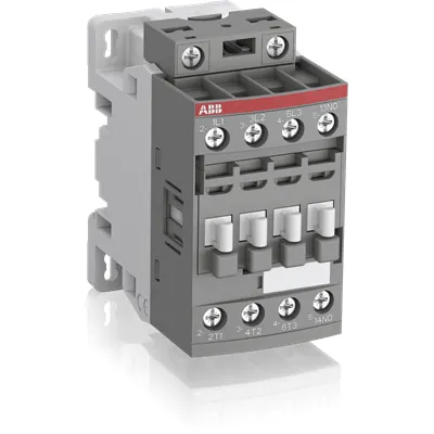
ABB Block Contactor 1SBL137001N1210 is a 3-pole control device designed for reliable motor and conveyor startups in industrial panels. In today’s factories, voltage swings and unstable networks can cause nuisance tripping and energy waste; this contactor’s wide control-voltage range helps maintain consistent operation without swapping coil variants. It adheres to IEC/EN 60947-1 and 60947-4-1, UL 60335-2-40, and carries CE/UKCA declarations, with an IP20 protection rating for safe panel mounting. The design emphasizes reliability and serviceability, supporting easy extension with add-on auxiliary blocks and a broad range of accessories. For integrators and maintenance teams, this translates to simpler stocking, faster commissioning, and lower total cost of ownership, while preserving robust performance in demanding environments.
Product Information
Extended Description
1SBL137001N1210 ABB: The AF09N00-30-10-12 is a 3 pole - 600 V UL, NEMA size N00 contactor with 1 built-in auxiliary contact and Screw, switching power circuits up to 25 A UL general use. Thanks to the AF technology, the contactor has a wide control voltage range (48-130 V 50/60 Hz and DC), managing large control voltage variations, reducing panel energy consumptions and ensuring distinct operations in unstable networks. Furthermore, surge protection is built-in, offering a compact solution. AF contactors have a block type design, can be easily extended with add-on auxiliary contact blocks and an additional wide range of accessories.
Minimum Order Quantity
1 piece
Instructions and Manuals
Installation instructions AF(C)09...38(Z)(B) Contactors, NF(C)(Z)(B)22...80E Contactor relays and CA4, CAL4, CAT4, CC4, LDC4 Accessories
Instructions and Manuals (Part 2)
Contactors and Overload relays guide
CAD Dimensional Drawing
Information - 2D and 3D files for CAD systems
Product Net Width
45 mm
Product Net Depth / Length
77 mm
Product Net Height
86 mm
Product Net Weight
0.27 kg
Number of Main Contacts NO
3
Number of Main Contacts NC
0
Number of Auxiliary Contacts NO
1
Number of Auxiliary Contacts NC
0
Number of Poles
3P
Standards
IEC/EN 60947-1, IEC/EN 60947-4-1, UL 60335-2-40 LZGH2 A2L, UL 60947-4-1, CSA C22.2 No. 60335-2-40 LZGH2 A2L, CSA C22.2 No. 60947-4-1
Rated Operational Voltage
Auxiliary Circuit 690 V | Main Circuit 690 V
Rated Frequency (f)
Auxiliary Circuit 50 / 60 Hz | Control Circuit 50 / 60 Hz | Main Circuit 50 / 60 Hz
Conventional Free-air Thermal Current (Ith)
acc. to IEC 60947-4-1, Open Contactors Θ = 40 °C 35 A | acc. to IEC 60947-5-1, Θ = 40 °C 16 A
Rated Operational Current AC-1 (Ie)
(690 V) 40 °C 25 A | (690 V) 60 °C 25 A | (690 V) 70 °C 22 A
Rated Operational Current AC-3 (Ie)
(415 V) 60 °C 9 A | (440 V) 60 °C 9 A | (500 V) 60 °C 9.5 A | (690 V) 60 °C 7 A | (380 / 400 V) 60 °C 9 A | (220 / 230 / 240 V) 60 °C 9 A
Rated Operational Current AC-3e (Ie)
(415 V) 60 °C 9 A | (440 V) 60 °C 9 A | (500 V) 60 °C 9.5 A | (690 V) 60 °C 7 A | (380 / 400 V) 60 °C 9 A | (220 / 230 / 240 V) 60 °C 9 A
Rated Operational Current AC-15 (Ie)
(500 V) 2 A | (690 V) 2 A | (24 / 127 V) 6 A | (220 / 240 V) 4 A | (400 / 440 V) 3 A
Rated Operational Current DC-13 (Ie)
(24 V) 6 A / 144 W | (48 V) 2.8 A / 134 W | (72 V) 1 A / 72 W | (110 V) 0.55 A / 60 W | (125 V) 0.55 A / 69 W | (220 V) 0.27 A / 60 W | (250 V) 0.27 A / 68 W | (400 V) 0.15 A / 60 W | (500 V) 0.13 A / 65 W | (600 V) 0.1 A / 60 W
Rated Operational Power AC-3 (Pe)
(400 V) 4 kW | (415 V) 4 kW | (440 V) 4 kW | (500 V) 5.5 kW | (690 V) 5.5 kW | (380 / 400 V) 4 kW | (220 / 230 / 240 V) 2.2 kW
Rated Operational Power AC-3e (Pe)
(415 V) 4 kW | (440 V) 4 kW | (500 V) 5.5 kW | (690 V) 5.5 kW | (380 / 400 V) 4 kW | (220 / 230 / 240 V) 2.2 kW
Rated Short-time Withstand Current Low Voltage (Icw)
at 40 °C Ambient Temp, in Free Air, from a Cold State 10 s 150 A | at 40 °C Ambient Temp, in Free Air, from a Cold State 15 min 35 A | at 40 °C Ambient Temp, in Free Air, from a Cold State 1 min 60 A | at 40 °C Ambient Temp, in Free Air, from a Cold State 1 s 300 A | at 40 °C Ambient Temp, in Free Air, from a Cold State 30 s 80 A | for 0.1 s 140 A | for 1 s 100 A
Maximum Breaking Capacity
cos phi=0.45 (cos phi=0.35 for Ie > 100 A) at 440 V 250 A | cos phi=0.45 (cos phi=0.35 for Ie > 100 A) at 690 V 106 A
Rated Insulation Voltage (Ui)
acc. to IEC 60947-4-1 690 V | acc. to IEC 60947-5-1 690 V | acc. to UL/CSA 600 V
Rated Impulse Withstand Voltage (Uimp)
6 kV
Maximum Electrical Switching Frequency
(AC-1) 600 cycles per hour | (AC-15) 1200 cycles per hour | (AC-2 / AC-4) 300 cycles per hour | (AC-3) 1200 cycles per hour | (DC-13) 900 cycles per hour
Maximum Mechanical Switching Frequency
3600 cycles per hour
Rated Control Circuit Voltage (Uc)
50 Hz 48 ... 130 V | 60 Hz 48 ... 130 V | DC Operation 48 ... 130 V
Power Loss
at 6 A per Pole 0.1 W | at Rated Operating Conditions AC-1 per Pole 0.8 W | at Rated Operating Conditions AC-3 per Pole 0.1 W
Operate Time
Between Coil De-energization and NC Contact Closing 13 ... 98 ms | Between Coil De-energization and NO Contact Opening 11 ... 95 ms | Between Coil Energization and NC Contact Opening 38 ... 90 ms | Between Coil Energization and NO Contact Closing 40 ... 95 ms
Mounting on DIN Rail
TH35-15 (35 x 15 mm Mounting Rail) acc. to IEC 60715 | TH35-7.5 (35 x 7.5 mm Mounting Rail) acc. to IEC 60715
Mounting by Screws (not supplied)
2 x M4 screws placed diagonally
Connecting Capacity Main Circuit
Flexible with Ferrule 1/2x 0.75 ... 6 mm² | Flexible with Insulated Ferrule 1x 0.75 ... 4 mm² | Flexible with Insulated Ferrule 2x 0.75 ... 2.5 mm² | Rigid Solid 1/2x 1 ... 4 mm² | Rigid Stranded 1/2x 1 ... 6 mm²
Connecting Capacity Auxiliary Circuit
Flexible with Ferrule 1/2x 0.75 ... 2.5 mm² | Flexible with Insulated Ferrule 2x 0.75 ... 1.5 mm² | Flexible with Insulated Ferrule 1x 0.75 ... 2.5 mm² | Rigid Solid 1/2x 1 ... 2.5 mm² | Rigid Stranded 1/2x 1 ... 2.5 mm²
Connecting Capacity Control Circuit
Flexible with Ferrule 1/2x 0.75 ... 2.5 mm² | Flexible with Insulated Ferrule 1x 0.75 ... 2.5 mm² | Flexible with Insulated Ferrule 2x 0.75 ... 1.5 mm² | Rigid Solid 1/2x 1 ... 2.5 mm² | Rigid Stranded 1/2x 1 ... 2.5 mm²
Wire Stripping Length
Auxiliary Circuit 10 mm | Control Circuit 10 mm | Main Circuit 10 mm
Degree of Protection
acc. to IEC 60529, IEC 60947-1, EN 60529 Auxiliary Terminals IP20 | acc. to IEC 60529, IEC 60947-1, EN 60529 Coil Terminals IP20 | acc. to IEC 60529, IEC 60947-1, EN 60529 Main Terminals IP20
Tightening Torque
Auxiliary Circuit 1.2 N·m | Control Circuit 1.2 N·m | Main Circuit 1.5 N·m
Terminal Type
Screw Terminals
Product Name
Block Contactor
NEMA Size
00
Continuous Current Rating NEMA
9 A
Horsepower Rating NEMA
(115 V AC) Single Phase 1/3 Hp | (200 V AC) Three Phase 1-1/2 Hp | (230 V AC) Single Phase 1 Hp | (230 V AC) Three Phase 1-1/2 Hp | (460 V AC) Three Phase 2 Hp | (575 V AC) Three Phase 2 Hp
Maximum Operating Voltage UL/CSA
Main Circuit 600 V
General Use Rating UL/CSA
(600 V AC) 25 A
Connecting Capacity Main Circuit UL/CSA
Rigid Solid 1/2x 16-10 AWG | Rigid Stranded 1/2x 16-10 AWG
Connecting Capacity Auxiliary Circuit UL/CSA
Rigid Solid 1/2x 18-14 AWG | Rigid Stranded 1/2x 18-14 AWG
Connecting Capacity Control Circuit UL/CSA
Rigid Solid 1/2x 18-14 AWG | Rigid Stranded 1/2x 18-14 AWG
Tightening Torque UL/CSA
Auxiliary Circuit 11 in·lb | Control Circuit 11 in·lb | Main Circuit 13 in·lb
Full Load Amps Motor Use
(120 V AC) Single Phase 3/4 A | (200 ... 208 V AC) Three Phase 2 A | (220 ... 240 V AC) Three Phase 2 A | (240 V AC) Single Phase 1-1/2 A | (440 ... 480 V AC) Three Phase 5 A | (550 ... 600 V AC) Three Phase 7-1/2 A
Ambient Air Temperature
Close to Contactor Fitted with Thermal O/L Relay -25 ... 60 °C | Close to Contactor without Thermal O/L Relay -40 ... 70 °C | Close to Contactor for Storage -60 ... +80 °C
Climatic Withstand
Category B according to IEC 60947-1 Annex Q
Maximum Operating Altitude Permissible
Without Derating 3000 m
Resistance to Shock acc. to IEC 60068-2-27
Closed, Shock Direction: A 30 g | Closed, Shock Direction: B1 25 g | Closed, Shock Direction: B2 15 g | Closed, Shock Direction: C1 25 g | Closed, Shock Direction: C2 25 g | Open, Shock Direction: A 30 g | Open, Shock Direction: B1 5 g | Open, Shock Direction: B2 15 g | Open, Shock Direction: C1 25 g | Open, Shock Direction: C2 25 g
Resistance to Vibrations
4g Closed Position & 2g Open position 5 ... 300 Hz
Pollution Degree
3
Conflict Minerals Reporting Template (CMRT)
CMRT - Conflict Minerals Reporting Template
REACH Declaration
REACH - Letter of Confirmation for block contactors, contactor relays, installation contactors, mini contactors, mini contactor relays, thermal overload relays, electronic overload relays and related accessories
RoHS Information
RoHS II declaration for block contactors, installation contactors, mini contactors, mini contactor relays, thermal overload relays, electronic overload relays and related accessories
RoHS Status
Following EU Directive 2011/65/EU and Amendment 2015/863 July 22, 2019
Toxic Substances Control Act - TSCA
Toxic Substances Control Act (TSCA) declaration for Contactors
WEEE Category
Product Not in WEEE Scope
End Of Life Disassembling Instructions
End of life instruction AF(S)09/12/16/26/30/38(Z)(B)(K)(RT) Contactors & NF(Z)(B)(K)(RT) Contactors relays
Sustainable Material Content in Packaging (wt. %)
Recycled Cardboard - 86 %
Sustainable Material Content in Product (wt. %)
Recycled Metal - 28 %
A2L Certificate – UL
UL-US A2L LZGH2 Certificate of Compliance AF09 ... AF38 3-pole contactors with screw terminals - UL 60335-2-40 Household and Similar Electrical Appliances - Safety - Part 2-40: Particular Requirements for Electrical Heat Pumps, Air-Conditioners and Dehumidifiers | UL-CA A2L LZGH2 Certificate of Compliance AF09 ... AF38 3-pole contactors with screw terminals - CSA C22.2 No. 60335-2-40 Household and Similar Electrical Appliances - Safety - Part 2-40: Particular Requirements for Electrical Heat Pumps, Air-Conditioners and Dehumidifiers
CB Certificate
CB Certificate AF09, AF12, AF16, AF09(Z)B, AF12(Z)B, AF16(Z)B 3 and 4-pole contactors, AFS09, AFS12, AFS16 safety contactors
CQC Certificate
CQC Certificate AF(C)09, AF(C)12, AF(C)16, AF09(Z)B, AF12(Z)B, AF16(Z)B 3 and 4-pole contactors, AFS09, AFS12, AFS16 safety contactors | CQC Certificate, Contactor, AF09,AF12,AF16, Made in China
Declaration of Conformity - CCC
CCC Declaration of Conformity, Contactor, AF*09, AF*12, AF*16, Made in France | CCC Declaration of Conformity, Contactor, AF09,AF12,AF16, Made in China
Declaration of Conformity - CE
EU Declaration of Conformity AF09N ... AF80N NEMA contactors
Declaration of Conformity - UKCA
UK Declaration of Conformity AF09N ... AF80N NEMA contactors
UL Certificate
UL-US Certificate of Compliance AF(C)(S)09(R/M/N)-..(L)(S)(K)...AF(C)(S)38(R/M/N)..(K) 3-pole contactors screw, spring and push-in spring terminals; LDC4 additional coil terminal block; LF16-4, LG16-4, LF38-4 and LH38-4 connecting strips, LD38-4 additional terminal block | UL-CA Certificate of Compliance AF(C)(S)09(R/M/N)-..(L)(S)(K)...AF(C)(S)38(R/M/N)..(K) 3-pole contactors screw, spring and push-in spring terminals; LDC4 additional coil terminal block; LF16-4, LG16-4, LF38-4 and LH38-4 connecting strips, LD38-4 additional terminal block
UL Listing Card
E312527
Package Level 1 Units
box 1 piece
Package Level 1 Width
87 mm
Package Level 1 Depth / Length
79 mm
Package Level 1 Height
47 mm
Package Level 1 Gross Weight
0.27 kg
Package Level 1 EAN
3471523016460
Package Level 3 Units
1296 piece
Object Classification Code
Q
ETIM 7
EC000066 - Power contactor, AC switching
ETIM 8
EC000066 - Power contactor, AC switching
ETIM 9
EC000066 - Power contactor, AC switching
eClass
V11.0 : 27371003
UNSPSC
39121529
Feature is a 3-pole main contact arrangement with 1 integrated auxiliary contact, delivering a compact 45 mm width and a robust 690 V rating. Business impact is immediate: it enables reliable motor control across common industrial voltages while reducing panel footprint and wiring complexity. Application-wise, this supports direct-on-line starts for conveyors, pumps, and fans in automation panels, with easy DIN rail mounting and screw-terminal connections for rapid installation. Feature describes AF technology with a wide control-voltage range of 48–130 V AC/50/60 Hz and DC operation, reducing spare-part inventory and enabling single-coil stocks across multiple regional networks. Complementary benefits include built-in surge protection and a block-design that accepts add-on auxiliary contact blocks, improving future-proofing and flexibility in evolving control schemes. Installation advantages include DIN-rail compatibility (TH35-15 or TH35-7.5), screw-terminals, and clear wiring guidance, helping technicians deploy with confidence and minimal commissioning time. In practice, customers gain energy efficiency from optimized coil operation (0.8 W per pole under rated AC-1, 0.1 W per pole at other conditions) and a smaller total cost of ownership due to reduced external protection needs and scalable control architecture.
Get a Quick Quote for a ABB 1SBL137001N1210
Chat with us on WhatsApp - fast responses guaranteed
Need to speak with someone? We'll call you back within 2 hours during business hours
Interested in ABB 1SBL137001N1210?
Enquire Now
FAQs
The coil accepts 48–130 V, available for AC 50/60 Hz or DC operation. This wide range reduces the need for multiple coil variants and simplifies stocking across different regions while maintaining reliable actuation even with supply fluctuations.
Yes. It complies with IEC 60947-1 and IEC 60947-4-1, UL 60335-2-40, CSA equivalencies, and carries CE/UKCA declarations. These certifications support global deployment in machinery and safety-critical applications.
Rated operational current is 25 A at AC-1 (690 V, 40–70 °C). For AC-3, ratings vary by voltage (e.g., up to 9 A at higher voltages). It’s suitable for motor starters, pumps, and conveyors in industrial panels with appropriate duty cycles.
Yes. The device includes 1 built-in auxiliary contact and is designed to be extended with add-on auxiliary contact blocks, enabling expanded control logic without replacing the base unit.
Mounting is via DIN rail (TH35-15 or TH35-7.5) or screws (M4). Main and auxiliary circuits use screw terminals with specified wire ranges, and wiring length is simplified by 10 mm stripping length guidance, supporting a neat, reliable panel installation.