ABB 1SBL156001R2022 Block Contactor - 12-20 VDC control
Part Number: 1SBL156001R2022
Quick Summary
Block Contactor AF technology from ABB provides reliable motor control for 3-pole machines in industrial panels. Many users struggle with voltage fluctuations that cause nuisance tripping and inconsistent starts. ABB AF technology widens the control voltage range to 12–20 VDC, improving reliability in unstable networks. The AF12Z-30-22-20 block contactor also ships with integrated surge protection and compact DIN-rail mounting. Key standards include IEC/EN 60947-1, IEC/EN 60947-4-1, and UL 60335-2-40 with IP20 protection, supporting safe, compliant installations. Businesses gain lower energy use, faster commissioning, and scalable protection across factory lines by leveraging this compact, high-performance solution. Its 3-pole, 2 NO/2 NC auxiliary contact arrangement enables flexible control wiring.
Product Information
Extended Description
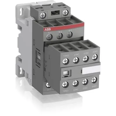
1SBL156001R2022 ABB: The AF12Z-30-22-20 is a 3 pole - 690 V IEC or 600 UL contactor with pre-mounted auxiliary contacts and screw terminals, controlling motors up to 5.5 kW / 400 V AC (AC-3) or 7-1/2 hp / 480 V UL and switching power circuits up to 28 A (AC-1) or 28 A UL general use. Thanks to the AF technology, the contactor has a wide control voltage range (12-20 V DC), managing large control voltage variations, reducing panel energy consumptions and ensuring distinct operations in unstable networks. Furthermore, surge protection is built-in, offering a compact solution. AF contactors have a block type design, can be easily extended with add-on auxiliary contact blocks and an additional wide range of accessories.
Minimum Order Quantity
1 piece
Data Sheet, Technical Information
1SBC100214C0202 - Main catalog Motor protection and control Manual motor starters, contactors and overload relays (PDF) - Edition 2024
Instructions and Manuals
Installation instructions AF(C)09...38(Z)(B) Contactors, NF(C)(Z)(B)22...80E Contactor relays and CA4, CAL4, CAT4, CC4, LDC4 Accessories
Instructions and Manuals (Part 2)
Contactors and Overload relays guide
CAD Dimensional Drawing
Information - 2D and 3D files for CAD systems
Product Net Width
45 mm
Product Net Depth / Length
110.5 mm
Product Net Height
86 mm
Product Net Weight
0.36 kg
Number of Main Contacts NO
3
Number of Main Contacts NC
0
Number of Auxiliary Contacts NO
2
Number of Auxiliary Contacts NC
2
Number of Poles
3P
Standards
IEC/EN 60947-1, IEC/EN 60947-4-1, UL 60335-2-40 LZGH2 A2L, UL 60947-4-1, CSA C22.2 No. 60335-2-40 LZGH2 A2L, CSA C22.2 No. 60947-4-1
Rated Operational Voltage
Auxiliary Circuit 690 V | Main Circuit 690 V
Rated Frequency (f)
Auxiliary Circuit 50 / 60 Hz | Main Circuit 50 / 60 Hz
Conventional Free-air Thermal Current (Ith)
acc. to IEC 60947-4-1, Open Contactors Θ = 40 °C 35 A | acc. to IEC 60947-5-1, Θ = 40 °C 16 A
Rated Operational Current AC-1 (Ie)
(690 V) 40 °C 28 A | (690 V) 60 °C 28 A | (690 V) 70 °C 24 A
Rated Operational Current AC-3 (Ie)
(415 V) 60 °C 12 A | (440 V) 60 °C 12 A | (500 V) 60 °C 12.5 A | (690 V) 60 °C 9 A | (380 / 400 V) 60 °C 12 A | (220 / 230 / 240 V) 60 °C 12 A
Rated Operational Current AC-3e (Ie)
(415 V) 60 °C 12 A | (440 V) 60 °C 12 A | (500 V) 60 °C 12.5 A | (690 V) 60 °C 9 A | (380 / 400 V) 60 °C 12 A | (220 / 230 / 240 V) 60 °C 12 A
Rated Operational Current AC-15 (Ie)
(500 V) 2 A | (690 V) 2 A | (24 / 127 V) 6 A | (220 / 240 V) 4 A | (400 / 440 V) 3 A
Rated Operational Current DC-1 (Ie)
(110 V) 1-Pole, 40 °C 15 A | (110 V) 1-Pole, 60 °C 15 A | (110 V) 1-Pole, 70 °C 15 A | (110 V) 2 Poles in Series, 40 °C 27 A | (110 V) 2 Poles in Series, 60 °C 27 A | (110 V) 2 Poles in Series, 70 °C 24 A | (110 V) 3 Poles in Series, 40 °C 27 A | (110 V) 3 Poles in Series, 60 °C 27 A | (110 V) 3 Poles in Series, 70 °C 24 A | (220 V) 2 Poles in Series, 40 °C 15 A | (220 V) 2 Poles in Series, 60 °C 15 A | (220 V) 2 Poles in Series, 70 °C 15 A | (220 V) 3 Poles in Series, 40 °C 27 A | (220 V) 3 Poles in Series, 60 °C 27 A | (220 V) 3 Poles in Series, 70 °C 24 A | (72 V) 1-Pole, 40 °C 27 A | (72 V) 1-Pole, 60 °C 27 A | (72 V) 1-Pole, 70 °C 24 A | (72 V) 2 Poles in Series, 40 °C 27 A | (72 V) 2 Poles in Series, 60 °C 27 A | (72 V) 2 Poles in Series, 70 °C 24 A | (72 V) 3 Poles in Series, 40 °C 27 A | (72 V) 3 Poles in Series, 60 °C 27 A | (72 V) 3 Poles in Series, 70 °C 24 A
Rated Operational Current DC-3 (Ie)
(110 V) 1-Pole, 40 °C 7 A | (110 V) 1-Pole, 60 °C 7 A | (110 V) 1-Pole, 70 °C 7 A | (110 V) 2 Poles in Series, 40 °C 27 A | (110 V) 2 Poles in Series, 60 °C 27 A | (110 V) 2 Poles in Series, 70 °C 24 A | (110 V) 3 Poles in Series, 40 °C 27 A | (110 V) 3 Poles in Series, 60 °C 27 A | (110 V) 3 Poles in Series, 70 °C 24 A | (220 V) 2 Poles in Series, 40 °C 7 A | (220 V) 2 Poles in Series, 60 °C 7 A | (220 V) 2 Poles in Series, 70 °C 7 A | (220 V) 3 Poles in Series, 40 °C 27 A | (220 V) 3 Poles in Series, 60 °C 27 A | (220 V) 3 Poles in Series, 70 °C 24 A | (72 V) 1-Pole, 40 °C 27 A | (72 V) 1-Pole, 60 °C 27 A | (72 V) 1-Pole, 70 °C 24 A | (72 V) 2 Poles in Series, 40 °C 27 A | (72 V) 2 Poles in Series, 60 °C 27 A | (72 V) 2 Poles in Series, 70 °C 24 A | (72 V) 3 Poles in Series, 40 °C 27 A | (72 V) 3 Poles in Series, 60 °C 27 A | (72 V) 3 Poles in Series, 70 °C 24 A
Rated Operational Current DC-5 (Ie)
(110 V) 1-Pole, 40 °C 4 A | (110 V) 1-Pole, 60 °C 4 A | (110 V) 1-Pole, 70 °C 4 A | (110 V) 2 Poles in Series, 40 °C 15 A | (110 V) 2 Poles in Series, 60 °C 15 A | (110 V) 2 Poles in Series, 70 °C 15 A | (110 V) 3 Poles in Series, 40 °C 27 A | (110 V) 3 Poles in Series, 60 °C 27 A | (110 V) 3 Poles in Series, 70 °C 24 A | (220 V) 2 Poles in Series, 40 °C 4 A | (220 V) 2 Poles in Series, 60 °C 4 A | (220 V) 2 Poles in Series, 70 °C 4 A | (220 V) 3 Poles in Series, 40 °C 12 A | (220 V) 3 Poles in Series, 60 °C 12 A | (220 V) 3 Poles in Series, 70 °C 12 A | (72 V) 1-Pole, 40 °C 12 A | (72 V) 1-Pole, 60 °C 12 A | (72 V) 1-Pole, 70 °C 12 A | (72 V) 2 Poles in Series, 40 °C 27 A | (72 V) 2 Poles in Series, 60 °C 27 A | (72 V) 2 Poles in Series, 70 °C 24 A | (72 V) 3 Poles in Series, 40 °C 27 A | (72 V) 3 Poles in Series, 60 °C 27 A | (72 V) 3 Poles in Series, 70 °C 24 A
Rated Operational Current DC-13 (Ie)
(24 V) 6 A / 144 W | (48 V) 2.8 A / 134 W | (72 V) 1 A / 72 W | (110 V) 0.55 A / 60 W | (125 V) 0.55 A / 69 W | (220 V) 0.27 A / 60 W | (250 V) 0.27 A / 68 W | (400 V) 0.15 A / 60 W | (500 V) 0.13 A / 65 W | (600 V) 0.1 A / 60 W
Rated Operational Power AC-3 (Pe)
(400 V) 5.5 kW | (415 V) 5.5 kW | (440 V) 5.5 kW | (500 V) 7.5 kW | (690 V) 7.5 kW | (380 / 400 V) 5.5 kW | (220 / 230 / 240 V) 3 kW
Rated Operational Power AC-3e (Pe)
(415 V) 5.5 kW | (440 V) 5.5 kW | (500 V) 7.5 kW | (690 V) 7.5 kW | (380 / 400 V) 5.5 kW | (220 / 230 / 240 V) 3 kW
Rated Short-time Withstand Current Low Voltage (Icw)
at 40 °C Ambient Temp, in Free Air, from a Cold State 10 s 150 A | at 40 °C Ambient Temp, in Free Air, from a Cold State 15 min 35 A | at 40 °C Ambient Temp, in Free Air, from a Cold State 1 min 60 A | at 40 °C Ambient Temp, in Free Air, from a Cold State 1 s 300 A | at 40 °C Ambient Temp, in Free Air, from a Cold State 30 s 80 A | for 0.1 s 140 A | for 1 s 100 A
Maximum Breaking Capacity
cos phi=0.45 (cos phi=0.35 for Ie > 100 A) at 440 V 250 A | cos phi=0.45 (cos phi=0.35 for Ie > 100 A) at 690 V 106 A
Rated Insulation Voltage (Ui)
acc. to IEC 60947-4-1 690 V | acc. to IEC 60947-5-1 690 V | acc. to UL/CSA 600 V
Rated Impulse Withstand Voltage (Uimp)
6 kV
Maximum Electrical Switching Frequency
(AC-1) 600 cycles per hour | (AC-15) 1200 cycles per hour | (AC-2 / AC-4) 300 cycles per hour | (AC-3) 1200 cycles per hour | (DC-13) 900 cycles per hour
Maximum Mechanical Switching Frequency
3600 cycles per hour
Rated Control Circuit Voltage (Uc)
DC Operation 12 ... 20 V
Power Loss
at 6 A per Pole 0.1 W | at Rated Operating Conditions AC-1 per Pole 1 W | at Rated Operating Conditions AC-3 per Pole 0.2 W
Operate Time
Between Coil De-energization and NC Contact Closing 13 ... 98 ms | Between Coil De-energization and NO Contact Opening 11 ... 95 ms | Between Coil Energization and NC Contact Opening 38 ... 90 ms | Between Coil Energization and NO Contact Closing 40 ... 95 ms
Mounting on DIN Rail
TH35-15 (35 x 15 mm Mounting Rail) acc. to IEC 60715 | TH35-7.5 (35 x 7.5 mm Mounting Rail) acc. to IEC 60715
Mounting by Screws (not supplied)
2 x M4 screws placed diagonally
Connecting Capacity Main Circuit
Flexible with Ferrule 1/2x 0.75 ... 6 mm² | Flexible with Insulated Ferrule 1x 0.75 ... 4 mm² | Flexible with Insulated Ferrule 2x 0.75 ... 2.5 mm² | Rigid Solid 1/2x 1 ... 4 mm² | Rigid Stranded 1/2x 1 ... 6 mm²
Connecting Capacity Auxiliary Circuit
Flexible with Ferrule 1/2x 0.75 ... 2.5 mm² | Flexible with Insulated Ferrule 2x 0.75 ... 1.5 mm² | Flexible with Insulated Ferrule 1x 0.75 ... 2.5 mm² | Rigid Solid 1/2x 1 ... 2.5 mm² | Rigid Stranded 1/2x 1 ... 2.5 mm²
Connecting Capacity Control Circuit
Flexible with Ferrule 1/2x 0.75 ... 2.5 mm² | Flexible with Insulated Ferrule 1x 0.75 ... 2.5 mm² | Flexible with Insulated Ferrule 2x 0.75 ... 1.5 mm² | Rigid Solid 1/2x 1 ... 2.5 mm² | Rigid Stranded 1/2x 1 ... 2.5 mm²
Wire Stripping Length
Auxiliary Circuit 10 mm | Control Circuit 10 mm | Main Circuit 10 mm
Degree of Protection
acc. to IEC 60529, IEC 60947-1, EN 60529 Auxiliary Terminals IP20 | acc. to IEC 60529, IEC 60947-1, EN 60529 Coil Terminals IP20 | acc. to IEC 60529, IEC 60947-1, EN 60529 Main Terminals IP20
Tightening Torque
Auxiliary Circuit 1.2 N·m | Control Circuit 1.2 N·m | Main Circuit 1.5 N·m
Terminal Type
Screw Terminals
Product Name
Block Contactor
NEMA Size
0
Continuous Current Rating NEMA
18 A
Horsepower Rating NEMA
(115 V AC) Single Phase 1 Hp | (200 V AC) Three Phase 3 Hp | (230 V AC) Single Phase 2 Hp | (230 V AC) Three Phase 3 Hp | (460 V AC) Three Phase 5 Hp | (575 V AC) Three Phase 5 Hp
Maximum Operating Voltage UL/CSA
Main Circuit 600 V
General Use Rating UL/CSA
(600 V AC) 28 A
Horsepower Rating UL/CSA
(120 V AC) Single Phase 1 hp | (200 ... 208 V AC) Three Phase 3 hp | (220 ... 240 V AC) Three Phase 3 hp | (240 V AC) Single Phase 2 hp | (440 ... 480 V AC) Three Phase 7-1/2 hp | (550 ... 600 V AC) Three Phase 10 hp
Connecting Capacity Main Circuit UL/CSA
Rigid Solid 1/2x 16-10 AWG | Rigid Stranded 1/2x 16-10 AWG
Connecting Capacity Auxiliary Circuit UL/CSA
Rigid Solid 1/2x 18-14 AWG | Rigid Stranded 1/2x 18-14 AWG
Connecting Capacity Control Circuit UL/CSA
Rigid Solid 1/2x 18-14 AWG | Rigid Stranded 1/2x 18-14 AWG
Tightening Torque UL/CSA
Auxiliary Circuit 11 in·lb | Control Circuit 11 in·lb | Main Circuit 13 in·lb
Full Load Amps Motor Use
(120 V AC) Single Phase 16 A | (200 ... 208 V AC) Three Phase 11 A | (220 ... 240 V AC) Three Phase 9.6 A | (240 V AC) Single Phase 12 A | (440 ... 480 V AC) Three Phase 11 A | (550 ... 600 V AC) Three Phase 11 A
Ambient Air Temperature
Close to Contactor Fitted with Thermal O/L Relay -25 ... 60 °C | Close to Contactor without Thermal O/L Relay -40 ... 70 °C | Close to Contactor for Storage -60 ... +80 °C
Climatic Withstand
Category B according to IEC 60947-1 Annex Q
Maximum Operating Altitude Permissible
Without Derating 3000 m
Resistance to Shock acc. to IEC 60068-2-27
Closed, Shock Direction: B1 25 g | Open, Shock Direction: B1 5 g | Shock Direction: A 30 g | Shock Direction: B2 15 g | Shock Direction: C1 25 g | Shock Direction: C2 25 g
Resistance to Vibrations
4g Closed Position & 2g Open position 5 ... 300 Hz
Pollution Degree
3
Conflict Minerals Reporting Template (CMRT)
CMRT - Conflict Minerals Reporting Template
REACH Declaration
REACH - Letter of Confirmation for block contactors, contactor relays, installation contactors, mini contactors, mini contactor relays, thermal overload relays, electronic overload relays and related accessories
RoHS Information
RoHS II declaration for block contactors, installation contactors, mini contactors, mini contactor relays, thermal overload relays, electronic overload relays and related accessories
RoHS Status
Following EU Directive 2011/65/EU and Amendment 2015/863 July 22, 2019
Toxic Substances Control Act - TSCA
Toxic Substances Control Act (TSCA) declaration for Contactors
WEEE B2C / B2B
Business To Business
WEEE Category
5. Small Equipment (No External Dimension More Than 50 cm)
End Of Life Disassembling Instructions
End of life instruction AF(S)09/12/16/26/30/38(Z)(B)(K)(RT) Contactors & NF(Z)(B)(K)(RT) Contactors relays
Environmental Product Declaration - EPD
Environmental Product Declaration - AF09/12/16(Z)(B) Contactors and NF(Z) Contactor relaysAF(S)09/12/16(Z)(B) Contactors and NF(Z)(B) Contactors Relays (FR)
Sustainable Material Content in Packaging (wt. %)
Recycled Cardboard - 86 %
Sustainable Material Content in Product (wt. %)
Recycled Metal - 28 %
A2L Certificate – UL
UL-US A2L LZGH2 Certificate of Compliance AF09 ... AF38 3-pole contactors with screw terminals - UL 60335-2-40 Household and Similar Electrical Appliances - Safety - Part 2-40: Particular Requirements for Electrical Heat Pumps, Air-Conditioners and Dehumidifiers | UL-CA A2L LZGH2 Certificate of Compliance AF09 ... AF38 3-pole contactors with screw terminals - CSA C22.2 No. 60335-2-40 Household and Similar Electrical Appliances - Safety - Part 2-40: Particular Requirements for Electrical Heat Pumps, Air-Conditioners and Dehumidifiers
ABS Certificate
ABS Certificate, AF(S)09 to AF(S)96 contactors, NF contactor relays and CA4, CC4, CAL4, CAT4 auxiliary contact blocks, TEF4 electronic timers
BV Certificate
BV Certificate AF(C)09...AF(C)38 3-pole and 4-pole contactors with screw and Push-in Spring terminals
CB Certificate
CB Certificate AF09, AF12, AF16, AF09(Z)B, AF12(Z)B, AF16(Z)B 3 and 4-pole contactors, AFS09, AFS12, AFS16 safety contactors
CCC Certificate
CCC Certificate AF09, AF12, AF16, AF09(Z)B, AF12(Z)B, AF16(Z)B 3 and 4-pole contactors, AFS09, AFS12, AFS16 safety contactors
CQC Certificate
CQC Certificate AF(C)09, AF(C)12, AF(C)16, AF09(Z)B, AF12(Z)B, AF16(Z)B 3 and 4-pole contactors, AFS09, AFS12, AFS16 safety contactors | CQC Certificate, Contactor, AF09,AF12,AF16, Made in China
Declaration of Conformity - CCC
CCC Declaration of Conformity, Contactor, AF*09, AF*12, AF*16, Made in France | CCC Declaration of Conformity, Contactor, AF09,AF12,AF16, Made in China
Declaration of Conformity - CE
EU Declaration of Conformity AF09... AF96-30-.., AF09...38(Z)-30..K 3-pole Contactors
Declaration of Conformity - UKCA
UK Declaration of Conformity AF09... AF96-30-.., AF09...38(Z)-30..K 3-pole Contactors
DNV Certificate
DNV Certificate AF(S)09...96 3-pole & AF09...80 4-pole contactors with screw, spring, push-in terminals
GOST Certificate
GOST_POCCFR.ME77.B07175.pdf
KC Certificate
KC Certificate AF12, AF16 3-pole contactors
LR Certificate
LRS Certificate AF(S)09..(K) ... AF96 3 and 4-pole contactors and CA(L)4..(K), CAT4, CC4 auxiliary contact blocks
RINA Certificate
Rina Certificate for AF(S)09...AF(S)96 contactors, NF contactor relays and accessories with screw,spring and push-in terminals
RMRS Certificate
RMRS Certificate AF(S)09(S)...AF(S)38 3-pole and 4-pole, AF(S)40..96 3-pole contactors with screw, push-in and spring terminals
UL Certificate
UL-US Certificate of Compliance AF(C)(S)09(R/M/N)-..(L)(S)(K)...AF(C)(S)38(R/M/N)..(K) 3-pole contactors screw, spring and push-in spring terminals; LDC4 additional coil terminal block; LF16-4, LG16-4, LF38-4 and LH38-4 connecting strips, LD38-4 additional terminal block | UL-CA Certificate of Compliance AF(C)(S)09(R/M/N)-..(L)(S)(K)...AF(C)(S)38(R/M/N)..(K) 3-pole contactors screw, spring and push-in spring terminals; LDC4 additional coil terminal block; LF16-4, LG16-4, LF38-4 and LH38-4 connecting strips, LD38-4 additional terminal block
UL Listing Card
E312527
Package Level 1 Units
box 1 piece
Package Level 1 Width
87 mm
Package Level 1 Depth / Length
113 mm
Package Level 1 Height
47 mm
Package Level 1 Gross Weight
0.36 kg
Package Level 1 EAN
3471523113701
Package Level 2 Units
box 18 piece
Package Level 2 Width
250 mm
Package Level 2 Depth / Length
300 mm
Package Level 2 Height
315 mm
Package Level 2 Gross Weight
6.48 kg
Package Level 3 Units
864 piece
Object Classification Code
Q
ETIM 7
EC000066 - Power contactor, AC switching
ETIM 8
EC000066 - Power contactor, AC switching
ETIM 9
EC000066 - Power contactor, AC switching
eClass
V11.0 : 27371003
UNSPSC
39121529
IDEA Granular Category Code (IGCC)
4758 >> Iec Contactors
Feature: Wide 12–20 VDC control voltage range enabled by AF technology. Business Impact: Reduces energy waste and stabilizes coil energization across voltage variances, lowering panel energy consumption and minimizing nuisance trips. Application: Ideal for panels in installations with fluctuating supplies, such as remote or high-load environments. Feature: 3-pole main circuit rated up to 690 V and 28 A AC-1 with 12 A AC-3. Business Impact: Supports high-start, medium-load motor starts with predictable performance, improving line efficiency and machine uptime. Application: Suitable for conveyors, pumps, and machine tools in manufacturing lines. Feature: Built-in surge protection and compact block design. Business Impact: Simplifies wiring, reduces panel footprint, and enhances protection against transient events, lowering maintenance costs. Application: Great for compact control cabinets where space is at a premium. Feature: Auxiliary contacts 2 NO / 2 NC + compatibility with add-on blocks. Business Impact: Expands control logic capabilities without separate relays, saving wiring and installation time. Application: Enables expanded signaling and interlocking schemes in automated cells. Feature: DIN rail mounting TH35-15 and screw-terminal connections. Business Impact: Speeds installation and simplifies field wiring with standard hardware, reducing commissioning time. Application: Common in switchgear, control panels, and retrofit projects. Feature: Compliance with IEC/EN 60947-1, 60947-4-1, UL 60335-2-40, plus IP20 protection. Business Impact: Ensures regulatory alignment and safe operation in harsh environments, supporting risk reduction and certification readiness. Application: Widely accepted in global applications across safety-critical equipment. Feature: Compact footprint and light weight (0.36 kg) with 45 mm width. Business Impact: Enables denser panel layouts, lower shipping costs, and easy integration into existing cabinets. Application: Suitable for tight automation enclosures and modular panel designs.
Get a Quick Quote for a ABB 1SBL156001R2022
Chat with us on WhatsApp - fast responses guaranteed
Need to speak with someone? We'll call you back within 2 hours during business hours
Interested in ABB 1SBL156001R2022?
Enquire Now
FAQs
The device is designed for TH35-15 DIN rails or mounting with two diagonal M4 screws. Use flexible ferrule 0.75–6 mm² or solid conductors 1/2 x 1…4 mm² for main circuit wiring, and 0.75–2.5 mm² for auxiliary. Tighten main terminals to 1.5 N·m and auxiliary/control terminals to 1.2 N·m. The screw-terminal design streamlines field wiring and supports straightforward expansion with add-on auxiliary contact blocks.
At 690 V, the Rated Operational Current AC-1 is 28 A (60 °C) and 24 A (70 °C). For AC-3, the device supports 12 A at 690 V. The AC-3e and DC-13/DC-5 ratings vary by voltage and pole configuration, with the unit achieving reliable switching for motor starts and protection relays in demanding environments.
Yes, the contactor includes built-in surge protection for resilient operation in fluctuating networks. It uses a block-type design that is easily extended with add-on auxiliary contact blocks (NO/NC), enabling flexible signaling, interlocking, and control logic without adding separate relays, which saves space and wiring time.
The device complies with IEC/EN 60947-1 and 60947-4-1, UL 60335-2-40, and CSA listings, with IP20 protection on auxiliary, coil, and main terminals. It also has a CE/UKCA footprint and multiple certificates (UL, CSA, CB, CCC, CE). This makes it suitable for safety-critical applications in global facilities, provided the installation adheres to local regulations.
The 12-20 VDC coil and AF technology reduce energy use and improve reliability, lowering energy waste and downtime. A compact footprint saves panel space, while integrated surge protection reduces protection hardware, installation time, and maintenance costs. With extended auxiliary contacts and DIN-rail compatibility, you can achieve faster commissioning, easier retrofits, and a lower total cost of ownership.