ABB 1SBL156060R2110 Block Contactor - IEC/UL 60947
Part Number: 1SBL156060R2110
Quick Summary
Block Contactor ABB 1SBL156060R2110 provides reliable motor control for 3‑phase systems in industrial automation and rolling stock applications. Operators often face voltage swings and wiring variations that cause intermittent trips and energy waste. This device meets IEC/EN 60947-4-1, UL 60947-4-1, CSA C22.2 and EN 50155 (where applicable), delivering proven safety and compatibility across markets. The AF technology enables a wide control voltage range and built‑in surge protection, while the compact, modular block design supports easy expansion with auxiliary contact blocks. In practice, this means faster panel assembly, fewer spare parts, and predictable performance in unstable networks, reducing downtime and total cost of ownership.
Product Information
Extended Description
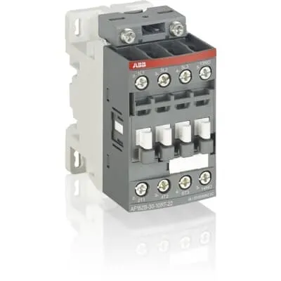
1SBL156060R2110 ABB: The AF12ZB-30-10RT-21 is a 3 pole - 690 V IEC or 600 UL contactor with 1 built-in auxiliary contact and Ring-Tongue Terminals, controlling motors up to 5.5 kW / 400 V AC (AC-3) or 7-1/2 hp / 480 V UL and switching power circuits up to 28 A (AC-1) or 28 A UL general use. Thanks to the AF technology, the contactor has a wide control voltage range (24-60 V 50/60 Hz and 20-60 V DC), managing large control voltage variations, reducing panel energy consumptions and ensuring distinct operations in unstable networks. Furthermore, surge protection is built-in, offering a compact solution. AF contactors have a block type design, can be easily extended with add-on auxiliary contact blocks and an additional wide range of accessories.
Minimum Order Quantity
1 piece
Customs Tariff Number
85364900
Data Sheet, Technical Information
Motor control and protection for Rolling stock application_PDF
Instructions and Manuals
Installation instructions AF09...38(Z)B-..RT Contactors, NF(Z)B..ERT Contactor relays and CA4..RT, CAL4..RT, CAT4..RT, LDC4RT Accessories
Instructions and Manuals (Part 2)
Contactors and Overload relays guide
CAD Dimensional Drawing
Information - 2D and 3D files for CAD systems
Product Net Width
45 mm
Product Net Depth / Length
77 mm
Product Net Height
86 mm
Product Net Weight
0.32 kg
Number of Main Contacts NO
3
Number of Main Contacts NC
0
Number of Auxiliary Contacts NO
1
Number of Auxiliary Contacts NC
0
Number of Poles
3P
Standards
IEC/EN 60947-1, IEC/EN 60947-4-1, UL 60947-4-1, CSA C22.2 No. 60947-4-1, IEC 60077-1 (applicable parts), IEC 60077-2 (applicable parts), EN 50155 (applicable parts), TR CU 001/2011, IEC 61373, For compliance confirmation on applicable parts based on your application and combination, please consult your ABB sales representatives.
Rated Operational Voltage
Auxiliary Circuit 690 V | Main Circuit 690 V
Rated Frequency (f)
Auxiliary Circuit 50 / 60 Hz | Control Circuit 50 / 60 Hz | Main Circuit 50 / 60 Hz
Conventional Free-air Thermal Current (Ith)
acc. to IEC 60947-4-1, Open Contactors Θ = 40 °C 35 A | acc. to IEC 60947-5-1, Θ = 40 °C 16 A
Rated Operational Current AC-1 (Ie)
(690 V) 40 °C 28 A | (690 V) 60 °C 28 A | (690 V) 70 °C 24 A
Rated Operational Current AC-3 (Ie)
(415 V) 60 °C 12 A | (440 V) 60 °C 12 A | (500 V) 60 °C 12.5 A | (690 V) 60 °C 9 A | (380 / 400 V) 60 °C 12 A | (220 / 230 / 240 V) 60 °C 12 A
Rated Operational Current AC-3e (Ie)
(415 V) 60 °C 12 A | (440 V) 60 °C 12 A | (500 V) 60 °C 12.5 A | (690 V) 60 °C 9 A | (380 / 400 V) 60 °C 12 A | (220 / 230 / 240 V) 60 °C 12 A
Rated Operational Current AC-15 (Ie)
(500 V) 2 A | (690 V) 2 A | (24 / 127 V) 6 A | (220 / 240 V) 4 A | (400 / 440 V) 3 A
Rated Operational Current DC-1 (Ie)
(110 V) 1-Pole, 40 °C 15 A | (110 V) 1-Pole, 60 °C 15 A | (110 V) 1-Pole, 70 °C 15 A | (110 V) 2 Poles in Series, 40 °C 27 A | (110 V) 2 Poles in Series, 60 °C 27 A | (110 V) 2 Poles in Series, 70 °C 24 A | (110 V) 3 Poles in Series, 40 °C 27 A | (110 V) 3 Poles in Series, 60 °C 27 A | (110 V) 3 Poles in Series, 70 °C 24 A | (220 V) 2 Poles in Series, 40 °C 15 A | (220 V) 2 Poles in Series, 60 °C 15 A | (220 V) 2 Poles in Series, 70 °C 15 A | (220 V) 3 Poles in Series, 40 °C 27 A | (220 V) 3 Poles in Series, 60 °C 27 A | (220 V) 3 Poles in Series, 70 °C 24 A | (72 V) 1-Pole, 40 °C 27 A | (72 V) 1-Pole, 60 °C 27 A | (72 V) 1-Pole, 70 °C 24 A | (72 V) 2 Poles in Series, 40 °C 27 A | (72 V) 2 Poles in Series, 60 °C 27 A | (72 V) 2 Poles in Series, 70 °C 24 A | (72 V) 3 Poles in Series, 40 °C 27 A | (72 V) 3 Poles in Series, 60 °C 27 A | (72 V) 3 Poles in Series, 70 °C 24 A
Rated Operational Current DC-3 (Ie)
(110 V) 1-Pole, 40 °C 7 A | (110 V) 1-Pole, 60 °C 7 A | (110 V) 1-Pole, 70 °C 7 A | (110 V) 2 Poles in Series, 40 °C 27 A | (110 V) 2 Poles in Series, 60 °C 27 A | (110 V) 2 Poles in Series, 70 °C 24 A | (110 V) 3 Poles in Series, 40 °C 27 A | (110 V) 3 Poles in Series, 60 °C 27 A | (110 V) 3 Poles in Series, 70 °C 24 A | (220 V) 2 Poles in Series, 40 °C 7 A | (220 V) 2 Poles in Series, 60 °C 7 A | (220 V) 2 Poles in Series, 70 °C 7 A | (220 V) 3 Poles in Series, 40 °C 27 A | (220 V) 3 Poles in Series, 60 °C 27 A | (220 V) 3 Poles in Series, 70 °C 24 A | (72 V) 1-Pole, 40 °C 27 A | (72 V) 1-Pole, 60 °C 27 A | (72 V) 1-Pole, 70 °C 24 A | (72 V) 2 Poles in Series, 40 °C 27 A | (72 V) 2 Poles in Series, 60 °C 27 A | (72 V) 2 Poles in Series, 70 °C 24 A | (72 V) 3 Poles in Series, 40 °C 27 A | (72 V) 3 Poles in Series, 60 °C 27 A | (72 V) 3 Poles in Series, 70 °C 24 A
Rated Operational Current DC-5 (Ie)
(110 V) 1-Pole, 40 °C 4 A | (110 V) 1-Pole, 60 °C 4 A | (110 V) 1-Pole, 70 °C 4 A | (110 V) 2 Poles in Series, 40 °C 15 A | (110 V) 2 Poles in Series, 60 °C 15 A | (110 V) 2 Poles in Series, 70 °C 15 A | (110 V) 3 Poles in Series, 40 °C 27 A | (110 V) 3 Poles in Series, 60 °C 27 A | (110 V) 3 Poles in Series, 70 °C 24 A | (220 V) 2 Poles in Series, 40 °C 4 A | (220 V) 2 Poles in Series, 60 °C 4 A | (220 V) 2 Poles in Series, 70 °C 4 A | (220 V) 3 Poles in Series, 40 °C 12 A | (220 V) 3 Poles in Series, 60 °C 12 A | (220 V) 3 Poles in Series, 70 °C 12 A | (72 V) 1-Pole, 40 °C 12 A | (72 V) 1-Pole, 60 °C 12 A | (72 V) 1-Pole, 70 °C 12 A | (72 V) 2 Poles in Series, 40 °C 27 A | (72 V) 2 Poles in Series, 60 °C 27 A | (72 V) 2 Poles in Series, 70 °C 24 A | (72 V) 3 Poles in Series, 40 °C 27 A | (72 V) 3 Poles in Series, 60 °C 27 A | (72 V) 3 Poles in Series, 70 °C 24 A
Rated Operational Current DC-13 (Ie)
(24 V) 6 A / 144 W | (48 V) 2.8 A / 134 W | (72 V) 1 A / 72 W | (110 V) 0.55 A / 60 W | (125 V) 0.55 A / 69 W | (220 V) 0.27 A / 60 W | (250 V) 0.27 A / 68 W | (400 V) 0.15 A / 60 W | (500 V) 0.13 A / 65 W | (600 V) 0.1 A / 60 W
Rated Operational Power AC-3 (Pe)
(415 V) 5.5 kW | (440 V) 5.5 kW | (500 V) 7.5 kW | (690 V) 7.5 kW | (380 / 400 V) 5.5 kW | (220 / 230 / 240 V) 3 kW
Rated Operational Power AC-3e (Pe)
(415 V) 5.5 kW | (440 V) 5.5 kW | (500 V) 7.5 kW | (690 V) 7.5 kW | (380 / 400 V) 5.5 kW | (220 / 230 / 240 V) 3 kW
Rated Short-time Withstand Current Low Voltage (Icw)
at 40 °C Ambient Temp, in Free Air, from a Cold State 10 s 150 A | at 40 °C Ambient Temp, in Free Air, from a Cold State 15 min 35 A | at 40 °C Ambient Temp, in Free Air, from a Cold State 1 min 60 A | at 40 °C Ambient Temp, in Free Air, from a Cold State 1 s 300 A | at 40 °C Ambient Temp, in Free Air, from a Cold State 30 s 80 A | for 0.1 s 140 A | for 1 s 100 A
Maximum Breaking Capacity
cos phi=0.45 (cos phi=0.35 for Ie > 100 A) at 440 V 250 A | cos phi=0.45 (cos phi=0.35 for Ie > 100 A) at 690 V 106 A
Rated Insulation Voltage (Ui)
acc. to IEC 60947-4-1 690 V | acc. to IEC 60947-5-1 690 V | acc. to UL/CSA 600 V
Rated Impulse Withstand Voltage (Uimp)
6 kV
Maximum Electrical Switching Frequency
(AC-1) 600 cycles per hour | (AC-15) 1200 cycles per hour | (AC-2 / AC-4) 300 cycles per hour | (AC-3) 1200 cycles per hour | (DC-13) 900 cycles per hour
Maximum Mechanical Switching Frequency
3600 cycles per hour
Rated Control Circuit Voltage (Uc)
50 Hz 24 ... 60 V | 60 Hz 24 ... 60 V | DC Operation 20 ... 60 V
Power Loss
at 6 A per Pole 0.1 W | at Rated Operating Conditions AC-1 per Pole 1 W | at Rated Operating Conditions AC-3 per Pole 0.2 W
Operate Time
Between Coil De-energization and NC Contact Closing 13 ... 98 ms | Between Coil De-energization and NO Contact Opening 11 ... 95 ms | Between Coil Energization and NC Contact Opening 38 ... 90 ms | Between Coil Energization and NO Contact Closing 40 ... 95 ms
Mounting on DIN Rail
TH35-15 (35 x 15 mm Mounting Rail) acc. to IEC 60715 | TH35-7.5 (35 x 7.5 mm Mounting Rail) acc. to IEC 60715
Mounting by Screws (not supplied)
2 x M4 screws placed diagonally
Degree of Protection
acc. to IEC 60529, IEC 60947-1, EN 60529 Auxiliary Terminals IP10 | acc. to IEC 60529, IEC 60947-1, EN 60529 Coil Terminals IP10 | acc. to IEC 60529, IEC 60947-1, EN 60529 Main Terminals IP10
Tightening Torque
Auxiliary Circuit 1.2 N·m | Control Circuit 1.2 N·m | Main Circuit 1.5 N·m
Terminal Type
Ring-Tongue Terminals
Product Name
Block Contactor
NEMA Size
0
Continuous Current Rating NEMA
18 A
Horsepower Rating NEMA
(115 V AC) Single Phase 1 Hp | (200 V AC) Three Phase 3 Hp | (230 V AC) Single Phase 2 Hp | (230 V AC) Three Phase 3 Hp | (460 V AC) Three Phase 5 Hp | (575 V AC) Three Phase 5 Hp
Maximum Operating Voltage UL/CSA
Main Circuit 600 V
General Use Rating UL/CSA
(600 V AC) 28 A
Horsepower Rating UL/CSA
(120 V AC) Single Phase 1 hp | (200 ... 208 V AC) Three Phase 3 hp | (220 ... 240 V AC) Three Phase 3 hp | (240 V AC) Single Phase 2 hp | (440 ... 480 V AC) Three Phase 7-1/2 hp | (550 ... 600 V AC) Three Phase 10 hp
Tightening Torque UL/CSA
Auxiliary Circuit 11 in·lb | Control Circuit 11 in·lb | Main Circuit 13 in·lb
Full Load Amps Motor Use
(120 V AC) Single Phase 16 A | (200 ... 208 V AC) Three Phase 11 A | (220 ... 240 V AC) Three Phase 9.6 A | (240 V AC) Single Phase 12 A | (440 ... 480 V AC) Three Phase 11 A | (550 ... 600 V AC) Three Phase 11 A
Ambient Air Temperature
Close to Contactor Fitted with Thermal O/L Relay -25 ... 60 °C | Close to Contactor without Thermal O/L Relay -40 ... 70 °C | Close to Contactor for Storage -60 ... +80 °C
Climatic Withstand
Category B according to IEC 60947-1 Annex Q
Maximum Operating Altitude Permissible
Without Derating 3000 m
Shock and Vibration Withstand acc. to IEC 61373
Category 1, Class B
Pollution Degree
3
Conflict Minerals Reporting Template (CMRT)
CMRT - Conflict Minerals Reporting Template
REACH Declaration
REACH - Letter of Confirmation for block contactors, contactor relays, installation contactors, mini contactors, mini contactor relays, thermal overload relays, electronic overload relays and related accessories
RoHS Information
RoHS II declaration for block contactors, installation contactors, mini contactors, mini contactor relays, thermal overload relays, electronic overload relays and related accessories
RoHS Status
Following EU Directive 2011/65/EU and Amendment 2015/863 July 22, 2019
SCIP
8d26875d-ef17-4edc-a76e-854d4481536b China (CN)
Toxic Substances Control Act - TSCA
Toxic Substances Control Act (TSCA) declaration for Contactors
WEEE B2C / B2B
Business To Business
WEEE Category
5. Small Equipment (No External Dimension More Than 50 cm)
End Of Life Disassembling Instructions
End of life instruction AF(S)09/12/16/26/30/38(Z)(B)(K)(RT) Contactors & NF(Z)(B)(K)(RT) Contactors relays
Environmental Product Declaration - EPD
Environmental Product Declaration - AF09/12/16(Z)(B) Contactors and NF(Z) Contactor relaysAF(S)09/12/16(Z)(B) Contactors and NF(Z)(B) Contactors Relays (FR) | Environmental Product Declaration - AF09/12/16(Z)(B) Contactors and NF(Z) Contactor relays
Sustainable Material Content in Packaging (wt. %)
Recycled Cardboard - 86 %
Sustainable Material Content in Product (wt. %)
Recycled Metal - 28 %
CB Certificate
CB Certificate AF09, AF12, AF16, AF09(Z)B, AF12(Z)B, AF16(Z)B 3 and 4-pole contactors, AFS09, AFS12, AFS16 safety contactors
CCC Certificate
CCC Certificate AF09, AF12, AF16, AF09(Z)B, AF12(Z)B, AF16(Z)B 3 and 4-pole contactors, AFS09, AFS12, AFS16 safety contactors
CQC Certificate
CQC Certificate AF(C)09, AF(C)12, AF(C)16, AF09(Z)B, AF12(Z)B, AF16(Z)B 3 and 4-pole contactors, AFS09, AFS12, AFS16 safety contactors
Declaration of Conformity - CCC
CCC Declaration of Conformity, Contactor, AF*09, AF*12, AF*16, Made in France
Declaration of Conformity - CE
EU Declaration of Conformity AF09 to AF38(Z)B..RT 3 and 4-pole contactors
Declaration of Conformity - UKCA
UK Declaration of Conformity AF09 to AF38(Z)B..RT 3 and 4-pole contactors
UL Listing Card
UL_E312527
UR Certificate
UR Certificate of Compliance AF09...AF38(Z)B..RT 3-pole contactors with ring tongue terminals
Package Level 1 Units
box 1 piece
Package Level 1 Width
87 mm
Package Level 1 Depth / Length
79 mm
Package Level 1 Height
47 mm
Package Level 1 Gross Weight
0.32 kg
Package Level 1 EAN
3471523127913
Package Level 2 Units
box 27 piece
Package Level 2 Width
250 mm
Package Level 2 Depth / Length
300 mm
Package Level 2 Height
315 mm
Package Level 2 Gross Weight
17.28 kg
Package Level 3 Units
1296 piece
Object Classification Code
Q
ETIM 7
EC000066 - Power contactor, AC switching
ETIM 8
EC000066 - Power contactor, AC switching
ETIM 9
EC000066 - Power contactor, AC switching
eClass
V11.0 : 27371003
UNSPSC
39121529
IDEA Granular Category Code (IGCC)
4758 >> Iec Contactors
Feature AF technology enables a wide control voltage range (24-60 VAC and 20-60 VDC) which reduces wiring variations and panel energy use; Business Impact fewer supply voltage conversions and improved energy efficiency in automation lines; Application suitable for 3-phase motor control up to 5.5 kW at 400 V AC and compatible with add-on auxiliary contact blocks. Feature Built-in surge protection safeguards control circuits from transients common in industrial environments; Business Impact reduced maintenance costs and higher uptime; Application ideal for conveyors, pumps, and fans in harsh electrical networks. Feature Compact block design with 45 mm width, 77 mm depth, 86 mm height and 0.32 kg weight; Business Impact easy installation on DIN rails and space-saving panels; Application supports TH35‑15 or TH35‑7.5 mounting and fast retrofits. Feature Ring-Tongue terminals and rated torque specs (Main 1.5 N·m, Auxiliary 1.2 N·m); Business Impact secure, vibration-resistant connections; Application simplifies field wiring and service. Feature Three main NO contacts and one auxiliary NO contact; Business Impact clear status signaling and interlocking capability; Application enables robust motor control with simple expansion. Feature Rated operational voltage 690 V (main and auxiliary) and adequate insulation and impulse withstand; Business Impact supports high-power AC-1 and AC-3 loads with reliable isolation; Application suitable for 690 V machinery, lifts, and rolling stock systems.
Get a Quick Quote for a ABB 1SBL156060R2110
Chat with us on WhatsApp - fast responses guaranteed
Need to speak with someone? We'll call you back within 2 hours during business hours
Interested in ABB 1SBL156060R2110?
Enquire Now
FAQs
Mount the 1SBL156060R2110 on a standard TH35 DIN rail (TH35-15 or TH35-7.5) using two M4 screws placed diagonally. Use Ring-Tongue terminals for main, auxiliary, and coil connections and tighten to 1.5 N·m for main, 1.2 N·m for auxiliary. Ensure proper clearance and IP10 protection for both coil and terminals, and verify coil voltage is 24–60 V (AC or DC), with control wiring suited to 690 V mains.
Key specs include three NO main contacts and one NO auxiliary contact, rated for 690 V mains. Rated Operational Current AC-1 is up to 28 A at 690 V, AC-3 is 9 A at 690 V, and AC-3e mirrors AC-3 values. Power handling at AC-3 is up to 7.5 kW (690 V), with a 6 kV impulse withstand and a maximum switching frequency appropriate for AC-1 and AC-3 applications.
Yes. The ABB 1SBL156060R2110 is designed for motor control of 3-phase loads such as conveyors, pumps, and fans. It handles up to 5.5 kW at 400 V (AC-3) and 7.5 hp at 480 V UL, with surge protection and a wide control voltage range that minimizes wiring changes. Its DIN rail mounting and modular design support scalable automation in conveyors and pumping stations.
The device complies with IEC/EN 60947-1 and 60947-4-1, UL 60947-4-1, CSA C22.2 No. 60947-4-1, and EN 50155 where applicable. These certifications verify safe operation in industrial environments, interoperability with global electrical standards, and suitability for rolling stock and railway applications. This compliance helps reduce validation time for multinational projects and supports safety and regulatory requirements.
AF technology provides a wide control voltage range, reducing wiring variants and simplifying panel design, which lowers installation time and upfront costs. Built-in surge protection enhances reliability in unstable networks, reducing downtime. The compatible add-on auxiliary contact blocks allow scalable monitoring and interlocking without replacing the base unit, delivering lower total cost of ownership over the equipment lifecycle.