ABB AF12-30-10K-14 Block Contactor - IEC/UL 60947-4-1
Part Number: 1SBL157005R1410
Quick Summary
The AF12-30-10K-14 block contactor is a 3-pole device that reliably switches motors and power circuits up to 690 V. For engineers facing voltage fluctuations, its wide control voltage range reduces misoperation and energy waste by tolerating variations from 250 to 500 V (AC) or DC control. It is built to meet IEC/EN 60947-1 and IEC/EN 60947-4-1, UL/CSA 60947-4-1, and is compatible with CE and UKCA marking requirements, with built-in surge protection that enhances reliability in unstable networks. The compact block design, extendable auxiliary contact blocks, and a broad accessory ecosystem enable faster panel assembly and scalable wiring for growing systems, delivering tangible reductions in installation time and lifecycle costs.
Product Information
Extended Description
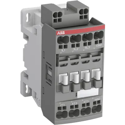
1SBL157005R1410 ABB: The AF12-30-10K-14 is a 3 pole - 690 V IEC or 600 UL contactor with 1 built-in auxiliary contact and push-in spring terminals, controlling motors up to 5.5 kW / 400 V AC (AC-3) or 7-1/2 hp / 480 V UL and switching power circuits up to 28 A (AC-1) or 28 A UL general use. Thanks to the AF technology, the contactor has a wide control voltage range (250-500 V 50/60 Hz and DC), managing large control voltage variations, reducing panel energy consumptions and ensuring distinct operations in unstable networks. Furthermore, surge protection is built-in, offering a compact solution. AF contactors have a block type design, can be easily extended with add-on auxiliary contact blocks and an additional wide range of accessories.
Minimum Order Quantity
1 piece
Data Sheet, Technical Information
1SBC100214C0202 - Main catalog Motor protection and control Manual motor starters, contactors and overload relays (PDF) - Edition 2024
Instructions and Manuals
Installation instructions AF(C)09...38(Z)(B)..K Contactors, NF(C)(Z)(B)..K Contactor relays and CA4..K, CAL4..K, LDC4K Accessories
Instructions and Manuals (Part 2)
Contactors and Overload relays guide
CAD Dimensional Drawing
Information - 2D and 3D files for CAD systems
Product Net Width
45 mm
Product Net Depth / Length
77 mm
Product Net Height
92.3 mm
Product Net Weight
0.325 kg
Number of Main Contacts NO
3
Number of Main Contacts NC
0
Number of Auxiliary Contacts NO
1
Number of Auxiliary Contacts NC
0
Number of Poles
3P
Standards
IEC/EN 60947-1, IEC/EN 60947-4-1, UL 60947-4-1, CSA C22.2 No. 60947-4-1
Rated Operational Voltage
Auxiliary Circuit 690 V | Main Circuit 690 V
Rated Frequency (f)
Auxiliary Circuit 50 / 60 Hz | Control Circuit 50 / 60 Hz | Main Circuit 50 / 60 Hz
Conventional Free-air Thermal Current (Ith)
acc. to IEC 60947-4-1, Open Contactors Θ = 40 °C 35 A | acc. to IEC 60947-5-1, Θ = 40 °C 16 A
Rated Operational Current AC-1 (Ie)
(690 V) 40 °C 28 A | (690 V) 60 °C 28 A | (690 V) 70 °C 24 A
Rated Operational Current AC-3 (Ie)
(415 V) 60 °C 12 A | (440 V) 60 °C 12 A | (500 V) 60 °C 12.5 A | (690 V) 60 °C 9 A | (380 / 400 V) 60 °C 12 A | (220 / 230 / 240 V) 60 °C 12 A
Rated Operational Current AC-3e (Ie)
(415 V) 60 °C 12 A | (440 V) 60 °C 12 A | (500 V) 60 °C 12.5 A | (690 V) 60 °C 9 A | (380 / 400 V) 60 °C 12 A | (220 / 230 / 240 V) 60 °C 12 A
Rated Operational Current AC-15 (Ie)
(500 V) 2 A | (690 V) 2 A | (24 / 127 V) 6 A | (220 / 240 V) 4 A | (400 / 440 V) 3 A
Rated Operational Current DC-1 (Ie)
(110 V) 1-Pole, 40 °C 15 A | (110 V) 1-Pole, 60 °C 15 A | (110 V) 1-Pole, 70 °C 15 A | (110 V) 2 Poles in Series, 40 °C 27 A | (110 V) 2 Poles in Series, 60 °C 27 A | (110 V) 2 Poles in Series, 70 °C 24 A | (110 V) 3 Poles in Series, 40 °C 27 A | (110 V) 3 Poles in Series, 60 °C 27 A | (110 V) 3 Poles in Series, 70 °C 24 A | (220 V) 2 Poles in Series, 40 °C 15 A | (220 V) 2 Poles in Series, 60 °C 15 A | (220 V) 2 Poles in Series, 70 °C 15 A | (220 V) 3 Poles in Series, 40 °C 27 A | (220 V) 3 Poles in Series, 60 °C 27 A | (220 V) 3 Poles in Series, 70 °C 24 A | (72 V) 1-Pole, 40 °C 27 A | (72 V) 1-Pole, 60 °C 27 A | (72 V) 1-Pole, 70 °C 24 A | (72 V) 2 Poles in Series, 40 °C 27 A | (72 V) 2 Poles in Series, 60 °C 27 A | (72 V) 2 Poles in Series, 70 °C 24 A | (72 V) 3 Poles in Series, 40 °C 27 A | (72 V) 3 Poles in Series, 60 °C 27 A | (72 V) 3 Poles in Series, 70 °C 24 A
Rated Operational Current DC-3 (Ie)
(110 V) 1-Pole, 40 °C 7 A | (110 V) 1-Pole, 60 °C 7 A | (110 V) 1-Pole, 70 °C 7 A | (110 V) 2 Poles in Series, 40 °C 27 A | (110 V) 2 Poles in Series, 60 °C 27 A | (110 V) 2 Poles in Series, 70 °C 24 A | (110 V) 3 Poles in Series, 40 °C 27 A | (110 V) 3 Poles in Series, 60 °C 27 A | (110 V) 3 Poles in Series, 70 °C 24 A | (220 V) 2 Poles in Series, 40 °C 7 A | (220 V) 2 Poles in Series, 60 °C 7 A | (220 V) 2 Poles in Series, 70 °C 7 A | (220 V) 3 Poles in Series, 40 °C 27 A | (220 V) 3 Poles in Series, 60 °C 27 A | (220 V) 3 Poles in Series, 70 °C 24 A | (72 V) 1-Pole, 40 °C 27 A | (72 V) 1-Pole, 60 °C 27 A | (72 V) 1-Pole, 70 °C 24 A | (72 V) 2 Poles in Series, 40 °C 27 A | (72 V) 2 Poles in Series, 60 °C 27 A | (72 V) 2 Poles in Series, 70 °C 24 A | (72 V) 3 Poles in Series, 40 °C 27 A | (72 V) 3 Poles in Series, 60 °C 27 A | (72 V) 3 Poles in Series, 70 °C 24 A
Rated Operational Current DC-5 (Ie)
(110 V) 1-Pole, 40 °C 4 A | (110 V) 1-Pole, 60 °C 4 A | (110 V) 1-Pole, 70 °C 4 A | (110 V) 2 Poles in Series, 40 °C 15 A | (110 V) 2 Poles in Series, 60 °C 15 A | (110 V) 2 Poles in Series, 70 °C 15 A | (110 V) 3 Poles in Series, 40 °C 27 A | (110 V) 3 Poles in Series, 60 °C 27 A | (110 V) 3 Poles in Series, 70 °C 24 A | (220 V) 2 Poles in Series, 40 °C 4 A | (220 V) 2 Poles in Series, 60 °C 4 A | (220 V) 2 Poles in Series, 70 °C 4 A | (220 V) 3 Poles in Series, 40 °C 12 A | (220 V) 3 Poles in Series, 60 °C 12 A | (220 V) 3 Poles in Series, 70 °C 12 A | (72 V) 1-Pole, 40 °C 12 A | (72 V) 1-Pole, 60 °C 12 A | (72 V) 1-Pole, 70 °C 12 A | (72 V) 2 Poles in Series, 40 °C 27 A | (72 V) 2 Poles in Series, 60 °C 27 A | (72 V) 2 Poles in Series, 70 °C 24 A | (72 V) 3 Poles in Series, 40 °C 27 A | (72 V) 3 Poles in Series, 60 °C 27 A | (72 V) 3 Poles in Series, 70 °C 24 A
Rated Operational Current DC-13 (Ie)
(24 V) 6 A / 144 W | (48 V) 2.8 A / 134 W | (72 V) 1 A / 72 W | (110 V) 0.55 A / 60 W | (125 V) 0.55 A / 69 W | (220 V) 0.27 A / 60 W | (250 V) 0.27 A / 68 W | (400 V) 0.15 A / 60 W | (500 V) 0.13 A / 65 W | (600 V) 0.1 A / 60 W
Rated Operational Power AC-3 (Pe)
(415 V) 5.5 kW | (440 V) 5.5 kW | (500 V) 7.5 kW | (690 V) 7.5 kW | (380 / 400 V) 5.5 kW | (220 / 230 / 240 V) 3 kW
Rated Operational Power AC-3e (Pe)
(415 V) 5.5 kW | (440 V) 5.5 kW | (500 V) 7.5 kW | (690 V) 7.5 kW | (380 / 400 V) 5.5 kW | (220 / 230 / 240 V) 3 kW
Rated Short-time Withstand Current Low Voltage (Icw)
at 40 °C Ambient Temp, in Free Air, from a Cold State 10 s 150 A | at 40 °C Ambient Temp, in Free Air, from a Cold State 15 min 35 A | at 40 °C Ambient Temp, in Free Air, from a Cold State 1 min 60 A | at 40 °C Ambient Temp, in Free Air, from a Cold State 1 s 300 A | at 40 °C Ambient Temp, in Free Air, from a Cold State 30 s 80 A | for 0.1 s 140 A | for 1 s 100 A
Maximum Breaking Capacity
cos phi=0.45 (cos phi=0.35 for Ie > 100 A) at 440 V 250 A | cos phi=0.45 (cos phi=0.35 for Ie > 100 A) at 690 V 90 A
Rated Insulation Voltage (Ui)
acc. to IEC 60947-4-1 690 V | acc. to IEC 60947-5-1 690 V | acc. to UL/CSA 600 V
Rated Impulse Withstand Voltage (Uimp)
6 kV
Maximum Electrical Switching Frequency
(AC-1) 600 cycles per hour | (AC-15) 1200 cycles per hour | (AC-2 / AC-4) 300 cycles per hour | (AC-3) 1200 cycles per hour | (DC-13) 900 cycles per hour
Maximum Mechanical Switching Frequency
3600 cycles per hour
Rated Control Circuit Voltage (Uc)
50 Hz 250 ... 500 V | 60 Hz 250 ... 500 V | DC Operation 250 ... 500 V
Power Loss
at 6 A per Pole 0.1 W | at Rated Operating Conditions AC-1 per Pole 1.43 W | at Rated Operating Conditions AC-3 per Pole 0.26 W
Operate Time
Between Coil De-energization and NC Contact Closing 13 ... 98 ms | Between Coil De-energization and NO Contact Opening 11 ... 95 ms | Between Coil Energization and NC Contact Opening 38 ... 90 ms | Between Coil Energization and NO Contact Closing 40 ... 95 ms
Mounting on DIN Rail
TH35-15 (35 x 15 mm Mounting Rail) acc. to IEC 60715 | TH35-7.5 (35 x 7.5 mm Mounting Rail) acc. to IEC 60715
Mounting by Screws (not supplied)
2 x M4 screws placed diagonally
Connecting Capacity Main Circuit
Flexible with Ferrule 1/2x 0.5 ... 4 mm² | Flexible with Insulated Ferrule 1x 0.5 ... 4 mm² | Flexible with Insulated Ferrule 2x 0.5 ... 2.5 mm² | Flexible 1/2x 0.5 ... 4 mm² | Rigid Solid 1/2x 1 ... 2.5 mm² | Rigid Stranded 1/2x 4 ... 6 mm²
Connecting Capacity Auxiliary Circuit
Flexible with Ferrule 1/2x 0.5 ... 2.5 mm² | Flexible with Insulated Ferrule 1/2x 0.5 ... 1.5 mm² | Flexible 1/2x 0.5 ... 2.5 mm² | Rigid Solid 1/2x 1 ... 2.5 mm²
Connecting Capacity Control Circuit
Flexible with Ferrule 1/2x 0.5 ... 2.5 mm² | Flexible with Insulated Ferrule 1/2x 0.5 ... 1.5 mm² | Flexible 1/2x 0.5 ... 2.5 mm² | Rigid Solid 1/2x 1 ... 2.5 mm²
Wire Stripping Length
Auxiliary Circuit 10 mm | Control Circuit 10 mm | Main Circuit 10 mm
Degree of Protection
acc. to IEC 60529, IEC 60947-1, EN 60529 Auxiliary Terminals IP20 | acc. to IEC 60529, IEC 60947-1, EN 60529 Coil Terminals IP20 | acc. to IEC 60529, IEC 60947-1, EN 60529 Main Terminals IP20
Terminal Type
Push-in Spring Terminals
Product Name
Block Contactor
NEMA Size
0
Continuous Current Rating NEMA
18 A
Horsepower Rating NEMA
(115 V AC) Single Phase 1 Hp | (200 V AC) Three Phase 3 Hp | (230 V AC) Single Phase 2 Hp | (230 V AC) Three Phase 3 Hp | (460 V AC) Three Phase 5 Hp | (575 V AC) Three Phase 5 Hp
Maximum Operating Voltage UL/CSA
Main Circuit 600 V
General Use Rating UL/CSA
(600 V AC) 28 A
Horsepower Rating UL/CSA
(120 V AC) Single Phase 1 hp | (200 ... 208 V AC) Three Phase 3 hp | (220 ... 240 V AC) Three Phase 3 hp | (240 V AC) Single Phase 2 hp | (440 ... 480 V AC) Three Phase 7-1/2 hp | (550 ... 600 V AC) Three Phase 10 hp
Connecting Capacity Main Circuit UL/CSA
Rigid Solid 1/2x 18-14 AWG | Rigid Stranded 1/2x 18-10 AWG
Connecting Capacity Auxiliary Circuit UL/CSA
Rigid Solid 1/2x 18-14 AWG
Connecting Capacity Control Circuit UL/CSA
Rigid Solid 1/2x 18-14 AWG
Full Load Amps Motor Use
(120 V AC) Single Phase 16 A | (200 ... 208 V AC) Three Phase 11 A | (220 ... 240 V AC) Three Phase 9.6 A | (240 V AC) Single Phase 12 A | (440 ... 480 V AC) Three Phase 11 A | (550 ... 600 V AC) Three Phase 11 A
Ambient Air Temperature
Close to Contactor without Thermal O/L Relay -40 ... 70 °C | Close to Contactor for Storage -60 ... +80 °C
Climatic Withstand
Category B according to IEC 60947-1 Annex Q
Maximum Operating Altitude Permissible
Without Derating 3000 m
Resistance to Vibrations
4g Closed Position & 2g Open position 5 ... 300 Hz
Pollution Degree
3
Conflict Minerals Reporting Template (CMRT)
CMRT - Conflict Minerals Reporting Template
REACH Declaration
REACH - Letter of Confirmation for block contactors, contactor relays, installation contactors, mini contactors, mini contactor relays, thermal overload relays, electronic overload relays and related accessories
RoHS Information
RoHS II declaration for block contactors, installation contactors, mini contactors, mini contactor relays, thermal overload relays, electronic overload relays and related accessories
RoHS Status
Following EU Directive 2011/65/EU and Amendment 2015/863 July 22, 2019
Toxic Substances Control Act - TSCA
Toxic Substances Control Act (TSCA) declaration for Contactors
WEEE B2C / B2B
Business To Business
WEEE Category
5. Small Equipment (No External Dimension More Than 50 cm)
End Of Life Disassembling Instructions
End of life instruction AF(S)09/12/16/26/30/38(Z)(B)(K)(RT) Contactors & NF(Z)(B)(K)(RT) Contactors relays
Environmental Product Declaration - EPD
Environmental Product Declaration - AF09/12/16(Z)(B) Contactors and NF(Z) Contactor relaysAF(S)09/12/16(Z)(B) Contactors and NF(Z)(B) Contactors Relays (FR)
Sustainable Material Content in Packaging (wt. %)
Recycled Cardboard - 86 %
Sustainable Material Content in Product (wt. %)
Recycled Metal - 28 %
ABS Certificate
ABS Certificate, AF(S)09 to AF(S)96 contactors, NF contactor relays and CA4, CC4, CAL4, CAT4 auxiliary contact blocks, TEF4 electronic timers
CB Certificate
CB Certificate AF09, AF12, AF16, AF09(Z)B, AF12(Z)B, AF16(Z)B 3 and 4-pole contactors, AFS09, AFS12, AFS16 safety contactors
CCC Certificate
CCC Certificate AF09, AF12, AF16, AF09(Z)B, AF12(Z)B, AF16(Z)B 3 and 4-pole contactors, AFS09, AFS12, AFS16 safety contactors
CQC Certificate
CQC Certificate AF(C)09, AF(C)12, AF(C)16, AF09(Z)B, AF12(Z)B, AF16(Z)B 3 and 4-pole contactors, AFS09, AFS12, AFS16 safety contactors | CQC Certificate, Contactor, AF09,AF12,AF16, Made in China
Declaration of Conformity - CCC
CCC Declaration of Conformity, Contactor, AF*09, AF*12, AF*16, Made in France | CCC Declaration of Conformity, Contactor, AF09,AF12,AF16, Made in China
Declaration of Conformity - CE
EU Declaration of Conformity AF09... AF96-30-.., AF09...38(Z)-30..K 3-pole Contactors
Declaration of Conformity - UKCA
UK Declaration of Conformity AF09... AF96-30-.., AF09...38(Z)-30..K 3-pole Contactors
DNV Certificate
DNV Certificate AF(S)09...96 3-pole & AF09...80 4-pole contactors with screw, spring, push-in terminals
LR Certificate
LRS Certificate AF(S)09..(K) ... AF96 3 and 4-pole contactors and CA(L)4..(K), CAT4, CC4 auxiliary contact blocks
RINA Certificate
Rina Certificate for AF(S)09...AF(S)96 contactors, NF contactor relays and accessories with screw,spring and push-in terminals
RMRS Certificate
RMRS Certificate AF(S)09(S)...AF(S)38 3-pole and 4-pole, AF(S)40..96 3-pole contactors with screw, push-in and spring terminals
UL Certificate
UL-US Certificate of Compliance AF(C)(S)09(R/M/N)-..(L)(S)(K)...AF(C)(S)38(R/M/N)..(K) 3-pole contactors screw, spring and push-in spring terminals; LDC4 additional coil terminal block; LF16-4, LG16-4, LF38-4 and LH38-4 connecting strips, LD38-4 additional terminal block | UL-CA Certificate of Compliance AF(C)(S)09(R/M/N)-..(L)(S)(K)...AF(C)(S)38(R/M/N)..(K) 3-pole contactors screw, spring and push-in spring terminals; LDC4 additional coil terminal block; LF16-4, LG16-4, LF38-4 and LH38-4 connecting strips, LD38-4 additional terminal block
Package Level 1 Units
box 1 piece
Package Level 1 Width
93 mm
Package Level 1 Depth / Length
86 mm
Package Level 1 Height
45 mm
Package Level 1 Gross Weight
0.34 kg
Package Level 1 EAN
3471523154346
Package Level 2 Units
box 21 piece
Package Level 2 Width
250 mm
Package Level 2 Depth / Length
300 mm
Package Level 2 Height
315 mm
Package Level 2 Gross Weight
15.3 kg
Package Level 3 Units
1080 piece
Object Classification Code
Q
ETIM 7
EC000066 - Power contactor, AC switching
ETIM 8
EC000066 - Power contactor, AC switching
ETIM 9
EC000066 - Power contactor, AC switching
eClass
V11.0 : 27371003
UNSPSC
39121529
IDEA Granular Category Code (IGCC)
4758 >> Iec Contactors
E-Number (Finland)
3707868
E-Number (Sweden)
3210595
Feature → Wide control voltage range enables a single coil solution across 250–500 V and DC operation, reducing stock and simplifying procurement. Business Impact → Fewer coil variants lowers inventory carrying costs while boosting panel reliability. Application → Ideal for panel builders integrating variable supply networks and mixed DC/AC control schemes. Feature → Built-in surge protection with AF technology delivers robust operation in unstable networks. Business Impact → Decreases nuisance tripping and hardware wear, extending equipment life. Application → Suitable for conveyors and process lines in manufacturing environments. Feature → Three main NO contacts plus one NO auxiliary contact provide clear status signaling and straightforward control wiring. Business Impact → Simplified wiring topology and improved operator feedback, reducing commissioning time. Application → Motor control and control circuits in control cabinets. Feature → Push-in spring terminals and 10 mm wire stripping length accelerate installation and reduce commissioning errors. Business Impact → Lower labor costs and higher wiring integrity in dense control panels. Application → End-user installations in automotive, packaging, or food & beverage lines. Feature → Rated AC-1 and AC-3 performance with DC-13 capability covers broad motor and load types. Business Impact → Wider application range and compliance with standard motor loads, lowering the need for alternative devices. Application → 5.5–7.5 kW AC-3 power at higher voltages, with DC options for auxiliary control. Feature → DIN rail mounting (TH35) compatibility and screw mounting option simplify retrofits and modular design. Business Impact → Faster upgrades, easier serviceability, and scalable automation architecture. Application → New builds and refurbishments across machine builders and panel shops. Feature → IP20 protection for coil and terminals plus robust mechanical switching frequencies. Business Impact → Enhanced environmental tolerance and longer service intervals in factory floors. Application → Harsh industrial settings where vibration and dust are present.
Get a Quick Quote for a ABB 1SBL157005R1410
Chat with us on WhatsApp - fast responses guaranteed
Need to speak with someone? We'll call you back within 2 hours during business hours
Interested in ABB 1SBL157005R1410?
Enquire Now
FAQs
Yes. The AF12-30-10K-14 supports DIN rail mounting using TH35-15 or TH35-7.5 profiles and can be secured with two M4 screws if screw mounting is required. Its push-in spring terminals simplify wiring, and wire stripping length is specified at 10 mm for consistent terminations.
For AC-1 at 690 V, the rated operational current is up to 28 A, with 60 °C and higher ratings as applicable. For AC-3 (motion loads), it typically supports up to 12 A at elevated voltages (e.g., 380–690 V). The device also handles DC-13 loads across a range of voltages, up to higher currents depending on configuration.
Yes, it includes built-in surge protection. The control circuit supports 250–500 V in AC operation and 250–500 V DC operation, enabling robust control across varying network conditions and reducing misoperation due to voltage spikes.
The device complies with IEC/EN 60947-1, IEC/EN 60947-4-1, UL 60947-4-1, and CSA C22.2 No. 60947-4-1, with CE, UKCA marking, and RoHS/REACH declarations where applicable. Multiple certificates (UL, CE, UKCA, etc.) support global deployment and regulatory conformity.
Flat-pack, compact block design with extendable auxiliary blocks reduces panel footprint and wiring complexity. Push-in terminals speed up commissioning, while low coil power loss (0.1–1.43 W per pole depending on operating condition) minimizes energy use. In addition, high switching frequency capability supports rapid cycling without excessive wear, lowering maintenance downtime and total cost of ownership.