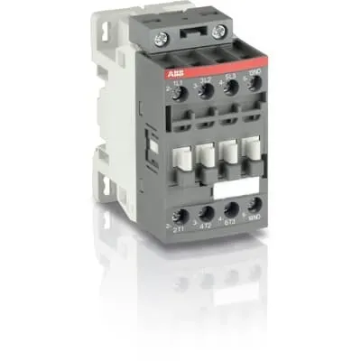
ABB AF12B-30-01-14 Contactor - 690V AC/DC, UL/CSA/CE
Part Number: 1SBL157061R1401
Quick Summary
The ABB AF12B-30-01-14 Contactor is a three-pole motor starter for industrial motor control. It helps operators manage motors reliably in demanding environments, even with fluctuating control voltages. This device meets IEC 60947-4-1, IEC 60947-1, and UL 60335-2-40/CSA standards, with EN 50155 considerations for rolling stock applications. Its AF technology supports a wide control voltage range and built-in surge protection, delivering resilience against network variability. By combining compact form with scalable accessory options, it enables cost-effective panel design and simplified maintenance, while supporting future expansion through add-on auxiliary contact blocks and DIN-rail mounting compatibility.
Product Information
Extended Description
1SBL157061R1401 ABB: The AF12B-30-01-14 is a 3 pole - 690 V IEC or 600 UL contactor with 1 built-in auxiliary contact and screw terminals, controlling motors up to 5.5 kW / 400 V AC (AC-3) or 7-1/2 hp / 480 V UL and switching power circuits up to 28 A (AC-1) or 28 A UL general use. Thanks to the AF technology, the contactor has a wide control voltage range (250-500 V 50/60 Hz and DC), managing large control voltage variations, reducing panel energy consumptions and ensuring distinct operations in unstable networks. Furthermore, surge protection is built-in, offering a compact solution. AF contactors have a block type design, can be easily extended with add-on auxiliary contact blocks and an additional wide range of accessories.
Minimum Order Quantity
1 piece
Customs Tariff Number
85364900
Data Sheet, Technical Information
Motor control and protection for Rolling stock application_PDF
Instructions and Manuals
Installation instructions AF(C)09...38(Z)(B) Contactors, NF(C)(Z)(B)22...80E Contactor relays and CA4, CAL4, CAT4, CC4, LDC4 Accessories
Instructions and Manuals (Part 2)
Contactors and Overload relays guide
CAD Dimensional Drawing
Information - 2D and 3D files for CAD systems
Product Net Width
45 mm
Product Net Depth / Length
77 mm
Product Net Height
86 mm
Product Net Weight
0.31 kg
Number of Main Contacts NO
3
Number of Main Contacts NC
0
Number of Auxiliary Contacts NO
0
Number of Auxiliary Contacts NC
1
Number of Poles
3P
Standards
IEC/EN 60947-1, IEC/EN 60947-4-1, UL 60335-2-40 LZGH2 A2L, UL 60947-4-1, CSA C22.2 No. 60335-2-40 LZGH2 A2L, CSA C22.2 No. 60947-4-1, IEC 60077-1 (applicable parts), IEC 60077-2 (applicable parts), EN 50155 (applicable parts), TR CU 001/2011, IEC 61373, For compliance confirmation on applicable parts based on your application and combination, please consult your ABB sales representatives.
Rated Operational Voltage
Auxiliary Circuit 690 V | Main Circuit 690 V
Rated Frequency (f)
Auxiliary Circuit 50 / 60 Hz | Control Circuit 50 / 60 Hz | Main Circuit 50 / 60 Hz
Conventional Free-air Thermal Current (Ith)
acc. to IEC 60947-4-1, Open Contactors Θ = 40 °C 35 A | acc. to IEC 60947-5-1, Θ = 40 °C 16 A
Rated Operational Current AC-1 (Ie)
(690 V) 40 °C 28 A | (690 V) 60 °C 28 A | (690 V) 70 °C 24 A
Rated Operational Current AC-3 (Ie)
(415 V) 60 °C 12 A | (440 V) 60 °C 12 A | (500 V) 60 °C 12.5 A | (690 V) 60 °C 9 A | (380 / 400 V) 60 °C 12 A | (220 / 230 / 240 V) 60 °C 12 A
Rated Operational Current AC-3e (Ie)
(415 V) 60 °C 12 A | (440 V) 60 °C 12 A | (500 V) 60 °C 12.5 A | (690 V) 60 °C 9 A | (380 / 400 V) 60 °C 12 A | (220 / 230 / 240 V) 60 °C 12 A
Rated Operational Current AC-15 (Ie)
(500 V) 2 A | (690 V) 2 A | (24 / 127 V) 6 A | (220 / 240 V) 4 A | (400 / 440 V) 3 A
Rated Operational Current DC-1 (Ie)
(110 V) 1-Pole, 40 °C 15 A | (110 V) 1-Pole, 60 °C 15 A | (110 V) 1-Pole, 70 °C 15 A | (110 V) 2 Poles in Series, 40 °C 27 A | (110 V) 2 Poles in Series, 60 °C 27 A | (110 V) 2 Poles in Series, 70 °C 24 A | (110 V) 3 Poles in Series, 40 °C 27 A | (110 V) 3 Poles in Series, 60 °C 27 A | (110 V) 3 Poles in Series, 70 °C 24 A | (220 V) 2 Poles in Series, 40 °C 15 A | (220 V) 2 Poles in Series, 60 °C 15 A | (220 V) 2 Poles in Series, 70 °C 15 A | (220 V) 3 Poles in Series, 40 °C 27 A | (220 V) 3 Poles in Series, 60 °C 27 A | (220 V) 3 Poles in Series, 70 °C 24 A | (72 V) 1-Pole, 40 °C 27 A | (72 V) 1-Pole, 60 °C 27 A | (72 V) 1-Pole, 70 °C 24 A | (72 V) 2 Poles in Series, 40 °C 27 A | (72 V) 2 Poles in Series, 60 °C 27 A | (72 V) 2 Poles in Series, 70 °C 24 A | (72 V) 3 Poles in Series, 40 °C 27 A | (72 V) 3 Poles in Series, 60 °C 27 A | (72 V) 3 Poles in Series, 70 °C 24 A
Rated Operational Current DC-3 (Ie)
(110 V) 1-Pole, 40 °C 7 A | (110 V) 1-Pole, 60 °C 7 A | (110 V) 1-Pole, 70 °C 7 A | (110 V) 2 Poles in Series, 40 °C 27 A | (110 V) 2 Poles in Series, 60 °C 27 A | (110 V) 2 Poles in Series, 70 °C 24 A | (110 V) 3 Poles in Series, 40 °C 27 A | (110 V) 3 Poles in Series, 60 °C 27 A | (110 V) 3 Poles in Series, 70 °C 24 A | (220 V) 2 Poles in Series, 40 °C 7 A | (220 V) 2 Poles in Series, 60 °C 7 A | (220 V) 2 Poles in Series, 70 °C 7 A | (220 V) 3 Poles in Series, 40 °C 27 A | (220 V) 3 Poles in Series, 60 °C 27 A | (220 V) 3 Poles in Series, 70 °C 24 A | (72 V) 1-Pole, 40 °C 27 A | (72 V) 1-Pole, 60 °C 27 A | (72 V) 1-Pole, 70 °C 24 A | (72 V) 2 Poles in Series, 40 °C 27 A | (72 V) 2 Poles in Series, 60 °C 27 A | (72 V) 2 Poles in Series, 70 °C 24 A | (72 V) 3 Poles in Series, 40 °C 27 A | (72 V) 3 Poles in Series, 60 °C 27 A | (72 V) 3 Poles in Series, 70 °C 24 A
Rated Operational Current DC-5 (Ie)
(110 V) 1-Pole, 40 °C 4 A | (110 V) 1-Pole, 60 °C 4 A | (110 V) 1-Pole, 70 °C 4 A | (110 V) 2 Poles in Series, 40 °C 15 A | (110 V) 2 Poles in Series, 60 °C 15 A | (110 V) 2 Poles in Series, 70 °C 15 A | (110 V) 3 Poles in Series, 40 °C 27 A | (110 V) 3 Poles in Series, 60 °C 27 A | (110 V) 3 Poles in Series, 70 °C 24 A | (220 V) 2 Poles in Series, 40 °C 4 A | (220 V) 2 Poles in Series, 60 °C 4 A | (220 V) 2 Poles in Series, 70 °C 4 A | (220 V) 3 Poles in Series, 40 °C 12 A | (220 V) 3 Poles in Series, 60 °C 12 A | (220 V) 3 Poles in Series, 70 °C 12 A | (72 V) 1-Pole, 40 °C 12 A | (72 V) 1-Pole, 60 °C 12 A | (72 V) 1-Pole, 70 °C 12 A | (72 V) 2 Poles in Series, 40 °C 27 A | (72 V) 2 Poles in Series, 60 °C 27 A | (72 V) 2 Poles in Series, 70 °C 24 A | (72 V) 3 Poles in Series, 40 °C 27 A | (72 V) 3 Poles in Series, 60 °C 27 A | (72 V) 3 Poles in Series, 70 °C 24 A
Rated Operational Current DC-13 (Ie)
(24 V) 6 A / 144 W | (48 V) 2.8 A / 134 W | (72 V) 1 A / 72 W | (110 V) 0.55 A / 60 W | (125 V) 0.55 A / 69 W | (220 V) 0.27 A / 60 W | (250 V) 0.27 A / 68 W | (400 V) 0.15 A / 60 W | (500 V) 0.13 A / 65 W | (600 V) 0.1 A / 60 W
Rated Operational Power AC-3 (Pe)
(415 V) 5.5 kW | (440 V) 5.5 kW | (500 V) 7.5 kW | (690 V) 7.5 kW | (380 / 400 V) 5.5 kW | (220 / 230 / 240 V) 3 kW
Rated Operational Power AC-3e (Pe)
(415 V) 5.5 kW | (440 V) 5.5 kW | (500 V) 7.5 kW | (690 V) 7.5 kW | (380 / 400 V) 5.5 kW | (220 / 230 / 240 V) 3 kW
Rated Short-time Withstand Current Low Voltage (Icw)
at 40 °C Ambient Temp, in Free Air, from a Cold State 10 s 150 A | at 40 °C Ambient Temp, in Free Air, from a Cold State 15 min 35 A | at 40 °C Ambient Temp, in Free Air, from a Cold State 1 min 60 A | at 40 °C Ambient Temp, in Free Air, from a Cold State 1 s 300 A | at 40 °C Ambient Temp, in Free Air, from a Cold State 30 s 80 A | for 0.1 s 140 A | for 1 s 100 A
Maximum Breaking Capacity
cos phi=0.45 (cos phi=0.35 for Ie > 100 A) at 440 V 250 A | cos phi=0.45 (cos phi=0.35 for Ie > 100 A) at 690 V 90 A
Rated Insulation Voltage (Ui)
acc. to IEC 60947-4-1 690 V | acc. to IEC 60947-5-1 690 V | acc. to UL/CSA 600 V
Rated Impulse Withstand Voltage (Uimp)
6 kV
Maximum Electrical Switching Frequency
(AC-1) 600 cycles per hour | (AC-15) 1200 cycles per hour | (AC-2 / AC-4) 300 cycles per hour | (AC-3) 1200 cycles per hour | (DC-13) 900 cycles per hour
Maximum Mechanical Switching Frequency
3600 cycles per hour
Rated Control Circuit Voltage (Uc)
50 Hz 250 ... 500 V | 60 Hz 250 ... 500 V | DC Operation 250 ... 500 V
Power Loss
at 6 A per Pole 0.1 W | at Rated Operating Conditions AC-1 per Pole 1 W | at Rated Operating Conditions AC-3 per Pole 0.2 W
Operate Time
Between Coil De-energization and NC Contact Closing 13 ... 98 ms | Between Coil De-energization and NO Contact Opening 11 ... 95 ms | Between Coil Energization and NC Contact Opening 38 ... 90 ms | Between Coil Energization and NO Contact Closing 40 ... 95 ms
Mounting on DIN Rail
TH35-15 (35 x 15 mm Mounting Rail) acc. to IEC 60715 | TH35-7.5 (35 x 7.5 mm Mounting Rail) acc. to IEC 60715
Mounting by Screws (not supplied)
2 x M4 screws placed diagonally
Connecting Capacity Main Circuit
Flexible with Ferrule 1/2x 0.75 ... 6 mm² | Flexible with Insulated Ferrule 1x 0.75 ... 4 mm² | Flexible with Insulated Ferrule 2x 0.75 ... 2.5 mm² | Rigid Solid 1/2x 1 ... 4 mm² | Rigid Stranded 1/2x 1 ... 6 mm²
Connecting Capacity Auxiliary Circuit
Rigid Solid 1/2x 1 ... 2.5 mm² | Rigid Stranded 1/2x 1 ... 2.5 mm²
Connecting Capacity Control Circuit
Flexible with Ferrule 1/2x 0.75 ... 2.5 mm² | Flexible with Insulated Ferrule 1x 0.75 ... 2.5 mm² | Flexible with Insulated Ferrule 2x 0.75 ... 1.5 mm² | Rigid Solid 1/2x 1 ... 2.5 mm² | Rigid Stranded 1/2x 1 ... 2.5 mm²
Wire Stripping Length
Auxiliary Circuit 10 mm | Control Circuit 10 mm | Main Circuit 10 mm
Degree of Protection
acc. to IEC 60529, IEC 60947-1, EN 60529 Auxiliary Terminals IP20 | acc. to IEC 60529, IEC 60947-1, EN 60529 Coil Terminals IP20 | acc. to IEC 60529, IEC 60947-1, EN 60529 Main Terminals IP20
Tightening Torque
Auxiliary Circuit 1.2 N·m | Control Circuit 1.2 N·m | Main Circuit 1.5 N·m
Terminal Type
Screw Terminals
Product Name
Block Contactor
NEMA Size
0
Continuous Current Rating NEMA
18 A
Horsepower Rating NEMA
(115 V AC) Single Phase 1 Hp | (200 V AC) Three Phase 3 Hp | (230 V AC) Single Phase 2 Hp | (230 V AC) Three Phase 3 Hp | (460 V AC) Three Phase 5 Hp | (575 V AC) Three Phase 5 Hp
Maximum Operating Voltage UL/CSA
Main Circuit 600 V
General Use Rating UL/CSA
(600 V AC) 28 A
Horsepower Rating UL/CSA
(120 V AC) Single Phase 1 hp | (200 ... 208 V AC) Three Phase 3 hp | (220 ... 240 V AC) Three Phase 3 hp | (240 V AC) Single Phase 2 hp | (440 ... 480 V AC) Three Phase 7-1/2 hp | (550 ... 600 V AC) Three Phase 10 hp
Connecting Capacity Main Circuit UL/CSA
Rigid Solid 1/2x 16-10 AWG | Rigid Stranded 1/2x 16-10 AWG
Connecting Capacity Auxiliary Circuit UL/CSA
Rigid Solid 1/2x 18-14 AWG | Rigid Stranded 1/2x 18-14 AWG
Connecting Capacity Control Circuit UL/CSA
Rigid Solid 1/2x 18-14 AWG | Rigid Stranded 1/2x 18-14 AWG
Tightening Torque UL/CSA
Auxiliary Circuit 11 in·lb | Control Circuit 11 in·lb | Main Circuit 13 in·lb
Full Load Amps Motor Use
(120 V AC) Single Phase 16 A | (200 ... 208 V AC) Three Phase 11 A | (220 ... 240 V AC) Three Phase 9.6 A | (240 V AC) Single Phase 12 A | (440 ... 480 V AC) Three Phase 11 A | (550 ... 600 V AC) Three Phase 11 A
Ambient Air Temperature
Close to Contactor Fitted with Thermal O/L Relay -25 ... 60 °C | Close to Contactor without Thermal O/L Relay -40 ... 70 °C | Close to Contactor for Storage -60 ... +80 °C
Climatic Withstand
Category B according to IEC 60947-1 Annex Q
Maximum Operating Altitude Permissible
Without Derating 3000 m
Shock and Vibration Withstand acc. to IEC 61373
Category 1, Class B
Pollution Degree
3
Conflict Minerals Reporting Template (CMRT)
CMRT - Conflict Minerals Reporting Template
REACH Declaration
REACH - Letter of Confirmation for block contactors, contactor relays, installation contactors, mini contactors, mini contactor relays, thermal overload relays, electronic overload relays and related accessories
RoHS Information
RoHS II declaration for block contactors, installation contactors, mini contactors, mini contactor relays, thermal overload relays, electronic overload relays and related accessories
RoHS Status
Following EU Directive 2011/65/EU and Amendment 2015/863 July 22, 2019
Toxic Substances Control Act - TSCA
Toxic Substances Control Act (TSCA) declaration for Contactors
WEEE B2C / B2B
Business To Business
WEEE Category
5. Small Equipment (No External Dimension More Than 50 cm)
End Of Life Disassembling Instructions
End of life instruction AF(S)09/12/16/26/30/38(Z)(B)(K)(RT) Contactors & NF(Z)(B)(K)(RT) Contactors relays
Environmental Product Declaration - EPD
Environmental Product Declaration - AF09/12/16(Z)(B) Contactors and NF(Z) Contactor relaysAF(S)09/12/16(Z)(B) Contactors and NF(Z)(B) Contactors Relays (FR)
Sustainable Material Content in Packaging (wt. %)
Recycled Cardboard - 86 %
Sustainable Material Content in Product (wt. %)
Recycled Metal - 28 %
A2L Certificate – UL
UL-US A2L LZGH2 Certificate of Compliance AF09 ... AF38 3-pole contactors with screw terminals - UL 60335-2-40 Household and Similar Electrical Appliances - Safety - Part 2-40: Particular Requirements for Electrical Heat Pumps, Air-Conditioners and Dehumidifiers | UL-CA A2L LZGH2 Certificate of Compliance AF09 ... AF38 3-pole contactors with screw terminals - CSA C22.2 No. 60335-2-40 Household and Similar Electrical Appliances - Safety - Part 2-40: Particular Requirements for Electrical Heat Pumps, Air-Conditioners and Dehumidifiers
CB Certificate
CB Certificate AF09, AF12, AF16, AF09(Z)B, AF12(Z)B, AF16(Z)B 3 and 4-pole contactors, AFS09, AFS12, AFS16 safety contactors
CCC Certificate
CCC Certificate AF09, AF12, AF16, AF09(Z)B, AF12(Z)B, AF16(Z)B 3 and 4-pole contactors, AFS09, AFS12, AFS16 safety contactors
CQC Certificate
CQC Certificate AF(C)09, AF(C)12, AF(C)16, AF09(Z)B, AF12(Z)B, AF16(Z)B 3 and 4-pole contactors, AFS09, AFS12, AFS16 safety contactors
Declaration of Conformity - CCC
CCC Declaration of Conformity, Contactor, AF*09, AF*12, AF*16, Made in France
Declaration of Conformity - CE
EU Declaration of Conformity AF09 ... AF38(Z)B..(K), AF40B ... AF96B 3 and 4-pole contactors
Declaration of Conformity - UKCA
UK Declaration of Conformity AF09 ... AF38(Z)B..(K), AF40B ... AF96B 3 and 4-pole contactors
GOST Certificate
GOST_POCCFR.ME77.B07175.pdf
KC Certificate
KC Certificate AF12, AF16 3-pole contactors
UL Certificate
UL-US Certificate of Compliance AF(C)(S)09(R/M/N)-..(L)(S)(K)...AF(C)(S)38(R/M/N)..(K) 3-pole contactors screw, spring and push-in spring terminals; LDC4 additional coil terminal block; LF16-4, LG16-4, LF38-4 and LH38-4 connecting strips, LD38-4 additional terminal block | UL-CA Certificate of Compliance AF(C)(S)09(R/M/N)-..(L)(S)(K)...AF(C)(S)38(R/M/N)..(K) 3-pole contactors screw, spring and push-in spring terminals; LDC4 additional coil terminal block; LF16-4, LG16-4, LF38-4 and LH38-4 connecting strips, LD38-4 additional terminal block
UL Listing Card
E312527
Package Level 1 Units
box 1 piece
Package Level 1 Width
87 mm
Package Level 1 Depth / Length
79 mm
Package Level 1 Height
47 mm
Package Level 1 Gross Weight
0.31 kg
Package Level 1 EAN
3471523122147
Package Level 2 Units
box 27 piece
Package Level 2 Width
250 mm
Package Level 2 Depth / Length
300 mm
Package Level 2 Height
315 mm
Package Level 2 Gross Weight
16.74 kg
Package Level 3 Units
1296 piece
Object Classification Code
Q
ETIM 7
EC000066 - Power contactor, AC switching
ETIM 8
EC000066 - Power contactor, AC switching
ETIM 9
EC000066 - Power contactor, AC switching
eClass
V11.0 : 27371003
UNSPSC
39121529
IDEA Granular Category Code (IGCC)
4758 >> Iec Contactors
Feature → Business Impact → Application: AF technology enables a wide control voltage range of 250–500 V AC/DC, reducing control circuit design constraints and improving reliability in networks with voltage variation; this translates to fewer nuisance trips and lower energy waste in motors and drives in textile, packaging, and material handling lines. Feature → Built-in surge protection for the coil and main circuits reduces component failures and maintenance costs, increasing uptime for critical conveying systems and rolling stock applications. Feature → Three main NO contacts plus one NC auxiliary contact provide flexible control topology and simpler logic wiring, reducing cabinet space and enabling quick retrofits in compact control panels. Feature → 3P main contacts rated up to 690 V with AC-1 and AC-3/AC-3e performance, enabling motor control of up to 5.5 kW at 400 V and supporting broader industrial drives. Feature → DIN rail mounting and screw-terminal connections offer easy field installation and secure, vibration-resistant operation in control cabinets and motor starters. Feature → Compact dimensions (45 mm width, 77 mm depth, 86 mm height) and IP20 protection facilitate space-saving layouts and robust operation in harsh environments. Feature → Add-on auxiliary contact blocks extend control capabilities without replacing the base device, supporting scalable automation architectures. Feature → Wide compatibility with standard accessories (installation instructions and CAD drawings available) reduces engineering time and accelerates project timelines. Feature → 28 A general-use and 12 A AC-3 ratings ensure suitable protection for 3-phase motors and switching power circuits, aligning with common industrial loads and UL/CSA requirements. Feature → CE, UL/CSA, and IEC compliance provide assurance for cross-border procurement and end-user safety, enabling faster approvals and fewer certification hurdles.
Get a Quick Quote for a ABB 1SBL157061R1401
Chat with us on WhatsApp - fast responses guaranteed
Need to speak with someone? We'll call you back within 2 hours during business hours
Interested in ABB 1SBL157061R1401?
Enquire Now
FAQs
Mount the device on TH35-15 or TH35-7.5 DIN rails as per IEC 60715, ensuring the coil and main circuits have proper clearance. It uses screw terminals for main, auxiliary, and control circuits, allowing flexible wiring and secure connections with typical ferrule or solid conductors within the specified cross-sections. This setup supports quick panel layout changes and straightforward field maintenance.
For AC-1, the AF12B-30-01-14 is rated up to 28 A at 690 V (60 °C and 70 °C conditions vary). For AC-3, it is rated up to 12 A at 415–690 V depending on the exact voltage, temperature, and application. This makes it suitable for motor starting and switching of smaller to mid-size drives while maintaining appropriate thermal margins.
Yes. The AF12B-30-01-14 is specified with standards including IEC/EN 60947-1, IEC 60947-4-1, EN 50155 applicability, and related UL/CSA certifications. The device’s coil support for 250–500 V, plus built-in surge protection, helps meet the reliability and safety demands in rolling stock environments while enabling integration with rail-specific control logic.
The AF12B complies with IEC 60947-1 and IEC 60947-4-1, UL 60335-2-40, CSA equivalents, EN 50155 for rolling stock, and CE/UKCA declarations. These certifications support safety, interoperability, and regulatory compliance across international procurement, reducing project risk and validation time.
Built-in surge protection reduces coil stress and extends life, while wide control voltage range simplifies wiring and reduces panel design variations. The compact DIN-rail mountable form saves cabinet space, and add-on auxiliary blocks enable scalable control without replacing the base device. Overall, these features lower maintenance costs, shorten commissioning, and improve uptime for motor control in automation lines.