ABB Block Contactor 1SBL171101R4200 - 690V/IEC UL
Part Number: 1SBL171101R4200
Quick Summary
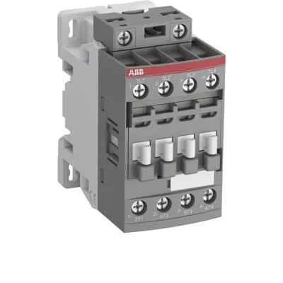
ABB Block Contactor 1SBL171101R4200 is a four-pole AC control device designed for reliable switching in industrial power circuits. It delivers compact, easily wired control with screw terminals and a block-style design that simplifies panel layouts and wiring harnesses. Operators increasingly seek devices that adapt to multiple supply voltages and mounting options, and this model answers with a 230–240 V AC 50/60 Hz coil (and 277 V AC 60 Hz) and DIN-rail mounting compatibility. The product aligns with essential standards such as IEC/EN 60947-1 and 60947-4-1, UL 60947-1 and 60947-4-1, plus IP20 protection for both main and control terminations. This combination supports global deployments, reduces panel depth, and improves maintainability, delivering reliable performance with lower lifecycle costs.
Product Information
Extended Description
1SBL171101R4200 ABB: The AFC16-04-00-42 is a 4-pole (4 N.C) - 690 V IEC or 600 V UL contactor withScrew terminals, mainly controlling power circuits up to 30 A (IEC AC-1) or 30 A UL general use. Within the AF platform, AFC contactors offer an optimized operating time for AC controlled applications with electromagnetic coil (control voltage : 230 ... 240 V AC 50 Hz / 277 V AC 60 Hz). AFC contactors have a block type design and can be easily extended with add-on auxiliary contact blocks and a wide range of additionnal accessories.
Minimum Order Quantity
1 piece
Customs Tariff Number
85364900
Data Sheet, Technical Information
1SBC100219C0201 AFC contactors for AC control applications_Catalog PDF
Instructions and Manuals
Installation instructions AF(C)09...38(Z)(B) Contactors, NF(C)(Z)(B)22...80E Contactor relays and CA4, CAL4, CAT4, CC4, LDC4 Accessories
Instructions and Manuals (Part 2)
Contactors and Overload relays guide
Product Net Width
45 mm
Product Net Depth / Length
77 mm
Product Net Height
86 mm
Product Net Weight
0.298 kg
Number of Main Contacts NO
0
Number of Main Contacts NC
4
Number of Auxiliary Contacts NO
0
Number of Auxiliary Contacts NC
0
Number of Poles
4P
Standards
IEC/EN 60947-1, IEC/EN 60947-4-1, UL 60947-1, UL 60947-4-1, CAN/CSA C22.2 No.60947-1, CAN/CSA C22.2 No.60947-4-1
Rated Operational Voltage
Main Circuit 690 V
Rated Frequency (f)
Auxiliary Circuit 50 / 60 Hz | Main Circuit 50 / 60 Hz
Conventional Free-air Thermal Current (Ith)
acc. to IEC 60947-4-1, Open Contactors Θ = 40 °C 30 A
Rated Operational Current AC-1 (Ie)
(690 V) 40 °C 30 A | (690 V) 60 °C 30 A | (690 V) 70 °C 26 A
Rated Operational Current AC-3 (Ie)
(415 V) 60 °C 5.2 A | (440 V) 60 °C 5.7 A | (500 V) 60 °C 5.7 A | (690 V) 60 °C 5.1 A | (380 / 400 V) 60 °C 5.2 A | (220 / 230 / 240 V) 60 °C 4.9 A
Rated Operational Power AC-3 (Pe)
(415 V) 2.2 kW | (440 V) 3 kW | (500 V) 3 kW | (690 V) 4 kW | (380 / 400 V) 2.2 kW | (220 / 230 / 240 V) 1.1 kW
Rated Short-time Withstand Current Low Voltage (Icw)
at 40 °C Ambient Temp, in Free Air, from a Cold State 10 s 150 A | at 40 °C Ambient Temp, in Free Air, from a Cold State 15 min 35 A | at 40 °C Ambient Temp, in Free Air, from a Cold State 1 min 60 A | at 40 °C Ambient Temp, in Free Air, from a Cold State 1 s 300 A | at 40 °C Ambient Temp, in Free Air, from a Cold State 30 s 80 A
Maximum Breaking Capacity
cos phi=0.45 (cos phi=0.35 for Ie > 100 A) at 440 V 250 A | cos phi=0.45 (cos phi=0.35 for Ie > 100 A) at 690 V 106 A
Rated Insulation Voltage (Ui)
acc. to IEC 60947-4-1 and VDE 0110 (Gr. C) 690 V | acc. to IEC 60947-5-1 and VDE 0110 (Gr. C) 690 V | acc. to UL/CSA 600 V
Rated Impulse Withstand Voltage (Uimp)
6 kV | Auxiliary Circuit 6 kV
Maximum Electrical Switching Frequency
(AC-1) 600 cycles per hour
Maximum Mechanical Switching Frequency
3600 cycles per hour
Rated Control Circuit Voltage (Uc)
50 Hz 230 ... 240 V | 60 Hz 277 V
Coil Consumption
Average Holding Value 50 / 60 Hz 8 V·A | Average Pull-in Value 50 Hz 70 V·A | Average Pull-in Value 60 Hz 66 V·A
Power Loss
at Rated Operating Conditions AC-1 per Pole 1.2 W | at Rated Operating Conditions AC-3 per Pole 0.35 W
Operate Time
Between Coil De-energization and NC Contact Closing 9 ... 20 ms | Between Coil De-energization and NO Contact Opening 4 ... 18 ms | Between Coil Energization and NC Contact Opening 7 ... 21 ms | Between Coil Energization and NO Contact Closing 10 ... 26 ms
Mounting on DIN Rail
TH35-15 (35 x 15 mm Mounting Rail) acc. to IEC 60715 | TH35-7.5 (35 x 7.5 mm Mounting Rail) acc. to IEC 60715
Mounting by Screws (not supplied)
2 x M4 screws placed diagonally
Connecting Capacity Main Circuit
Flexible with Ferrule 1/2x 0.75 ... 6 mm² | Flexible with Insulated Ferrule 1x 0.75 ... 4 mm² | Flexible with Insulated Ferrule 2x 0.75 ... 2.5 mm² | Flexible with Insulated Ferrule 2x 0.75 ... 2.5 mm² | Rigid 1/2x 1 ... 6 mm²
Connecting Capacity Auxiliary Circuit
Flexible with Ferrule 1/2x 0.75 ... 2.5 mm²
Connecting Capacity Control Circuit
Flexible with Ferrule 1/2x 0.75 ... 2.5 mm² | Flexible with Insulated Ferrule 1x 0.75 ... 2.5 mm² | Flexible with Insulated Ferrule 2x 0.75 ... 1.5 mm² | Flexible with Insulated Ferrule 1x 0.75 ... 2.5 mm² | Flexible with Insulated Ferrule 2x 0.75 ... 1.5 mm² | Rigid 1/2x 1 ... 2.5 mm²
Wire Stripping Length
Control Circuit 10 mm | Main Circuit 10 mm
Degree of Protection
acc. to IEC 60529, IEC 60947-1, EN 60529 Coil Terminals IP20 | acc. to IEC 60529, IEC 60947-1, EN 60529 Main Terminals IP20
Tightening Torque
Control Circuit 1.2 N·m | Main Circuit 1.5 N·m
Terminal Type
Screw Terminals
Product Name
Block Contactor
Maximum Operating Voltage UL/CSA
Main Circuit 600 V
General Use Rating UL/CSA
(600 V AC) 30 A
Tightening Torque UL/CSA
Control Circuit 11 in·lb | Main Circuit 13 in·lb
Ambient Air Temperature
Close to Contactor for Storage -60 ... +80 °C | Near Contactor for Operation in Free Air (0.85 ... 1.1 Uc) -40 ... +60 °C | Near Contactor for Operation in Free Air (Uc) -40 ... 70 °C
Climatic Withstand
Category B according to IEC 60947-1 Annex Q
Maximum Operating Altitude Permissible
Without Derating 3000 m
Resistance to Shock acc. to IEC 60068-2-27
Open, Shock Direction: B1 5 g | Shock Direction: A 30 g | Shock Direction: B1 20 g | Shock Direction: B2 15 g | Shock Direction: C1 25 g | Shock Direction: C2 25 g
Resistance to Vibrations
4g Closed Position & 2g Open position 5 ... 300 Hz
Pollution Degree
3
REACH Declaration
REACH - Letter of Confirmation for block contactors, contactor relays, installation contactors, mini contactors, mini contactor relays, thermal overload relays, electronic overload relays and related accessories
RoHS Information
RoHS II declaration for block contactors, installation contactors, mini contactors, mini contactor relays, thermal overload relays, electronic overload relays and related accessories
RoHS Status
Following EU Directive 2011/65/EU and Amendment 2015/863 July 22, 2019
Toxic Substances Control Act - TSCA
Toxic Substances Control Act (TSCA) declaration for Contactors
WEEE B2C / B2B
Business To Business
WEEE Category
5. Small Equipment (No External Dimension More Than 50 cm)
BV Certificate
BV Certificate AF(C)09...AF(C)38 3-pole and 4-pole contactors with screw and Push-in Spring terminals
CB Certificate
CB Certificate AFC09, AFC12, AFC16 3 or 4-pole contactors
CQC Certificate
CQC Certificate AF(C)09, AF(C)12, AF(C)16, AF09(Z)B, AF12(Z)B, AF16(Z)B 3 and 4-pole contactors, AFS09, AFS12, AFS16 safety contactors
Declaration of Conformity - CCC
CCC Declaration of Conformity, Contactor, AF*09, AF*12, AF*16, Made in France
Declaration of Conformity - CE
EU Declaration of Conformity AFC09 ... AFC80 4-pole Contactors
Declaration of Conformity - UKCA
UK Declaration of Conformity AFC09 ... AFC80 4-pole Contactors
DNV Certificate
DNV Certificate AFC09...96 3-pole & AFC09...80 4-pole contactors with screw, push-in terminals
RINA Certificate
Rina Certificate for AFC09...AFC96 3 pole and 4 pole contactors, NFC relays ,screw and spring terminals
UL Certificate
UL-US Certificate of Compliance AFC09 ... AFC38 4-pole contactors | UL-CA Certificate of Compliance AFC09 ... AFC38 4-pole contactors
Package Level 1 Units
box 1 piece
Package Level 1 Width
87 mm
Package Level 1 Depth / Length
79 mm
Package Level 1 Height
47 mm
Package Level 1 Gross Weight
0.324 kg
Package Level 1 EAN
3471523021082
Object Classification Code
Q
ETIM 7
EC000066 - Power contactor, AC switching
ETIM 8
EC000066 - Power contactor, AC switching
ETIM 9
EC000066 - Power contactor, AC switching
eClass
V11.0 : 27371003
UNSPSC
39121529
IDEA Granular Category Code (IGCC)
4755 >> Contactors
Feature → Business Impact → Application: The four-pole, four NC main contacts reduce controller count and wiring complexity, improving panel density and reliability for three-phase loads up to 30 A in IEC AC-1 service. This enables cleaner control architectures and lower installation time in manufacturing lines and packaging equipment. Feature → Business Impact → Application: Coil options of 230–240 V AC at 50/60 Hz or 277 V AC at 60 Hz provide global compatibility, enabling multinational installations without custom relays. This supports standardized panels across regions and reduces spare-part diversity. Feature → Business Impact → Application: Screw terminals with flexible conductor ranges (main 1/2x 0.75–6 mm²; auxiliary 1/2x 0.75–2.5 mm²) simplify field wiring, minimize termination failures, and speed commissioning in machine builders’ control cabinets. Feature → Business Impact → Application: DIN rail mounting (TH35-15 or TH35-7.5) and optional screw mounting streamline installation, permit quick swaps, and lower maintenance downtime in conveyor, pump, and fan control panels. Feature → Business Impact → Application: IP20 protection for both coil and main terminations provides safe operation inside standard enclosures, reducing risk of dust ingress and accidental contact in demanding factory environments. Feature → Business Impact → Application: The block design supports easy expansion with add-on auxiliary contact blocks, enabling scalable control for future upgrades in automation panels and MCCs. Feature → Business Impact → Application: Low coil power during hold (8 VA at 50/60 Hz) and modest pull-in power (66–70 VA) minimize energy loss and heat generation, contributing to cooler panels and lower energy costs in continuous-cycle applications. Feature → Business Impact → Application: High switching performance with AC-1 up to 600 cycles/hour and mechanical 3600 cycles/hour ensures long service life in automation tasks with frequent on/off control, such as packaging lines, material handling, and process skids.
Get a Quick Quote for a ABB 1SBL171101R4200
Chat with us on WhatsApp - fast responses guaranteed
Need to speak with someone? We'll call you back within 2 hours during business hours
Interested in ABB 1SBL171101R4200?
Enquire Now
FAQs
Yes. The device supports mounting on TH35-15 or TH35-7.5 DIN rails and can also be screwed to a chassis using two M4 screws. This provides flexible installation in standard control panels and MCCs, while preserving secure electrical connections and minimizing mounting space.
The coil accepts 230–240 V AC at 50/60 Hz or 277 V AC at 60 Hz. Choose based on your local supply: use 230–240 V for most worldwide 50/60 Hz networks, or 277 V for systems that operate at high-efficiency lighting or specific industrial controls. Both options maintain reliable pull-in and holding performance.
For AC-1 operation at 690 V, the device supports up to 30 A per pole with a 40 °C ambient rating and slightly reduced current at higher ambient temperatures. For AC-3 operation at 690 V, the device delivers about 5.1–5.7 A per pole, with a corresponding reduction in permissible electrical power. These ratings align with IEC/UL standards for motor and general purpose switching.
The contactor complies with IEC/EN 60947-1 and 60947-4-1, UL 60947-1 and 60947-4-1, and CAN/CSA equivalents, with CE, UKCA declarations where applicable. It also carries IP20 protection for coil and main terminations and supports RoHS, REACH, and related environmental declarations, ensuring regulatory alignment across global markets.
Expect reduced maintenance downtime due to robust screw-terminals and a compact block design that simplifies panel layout. Power loss is minimized (1.2 W per pole in AC-1, 0.35 W per pole in AC-3), improving panel cooling and energy efficiency. Its expandable auxiliary contact blocks support future automation upgrades without replacing the base device, delivering meaningful total cost of ownership savings.