ABB 1SBL171201R5100 Block Contactor - 690 V IEC/UL
Part Number: 1SBL171201R5100
Quick Summary
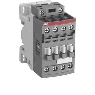
ABB 1SBL171201R5100 Block Contactor is a four-pole, 690 V AC control device designed to switch power circuits up to 30 A in industrial drives and general motor control. Engineers often contend with compact DIN-rail solutions that run hot under AC-3 loads or lack scalable accessories for future expansion. This device complies with IEC/EN 60947-4-1 and UL 60947-4-1, and carries CE and UKCA declarations, while offering IP20 protection for both coil and main terminals. With the AF platform, the coil drive remains efficient at 400–415 V AC 50 Hz or 480 V AC 60 Hz, and the block design accepts add-on auxiliary contact blocks and a wide range of accessories to simplify installation and reduce spare parts.
Product Information
Extended Description
1SBL171201R5100 ABB: The AFC16-40-00-51 is a 4-pole (4 N.O) - 690 V IEC or 600 V UL contactor withScrew terminals, mainly controlling power circuits up to 30 A (IEC AC-1) or 30 A UL general use. Within the AF platform, AFC contactors offer an optimized operating time for AC controlled applications with electromagnetic coil (control voltage : 400 ... 415 V AC 50 Hz / 480 V AC 60 Hz). AFC contactors have a block type design and can be easily extended with add-on auxiliary contact blocks and a wide range of additionnal accessories.
Minimum Order Quantity
1 piece
Customs Tariff Number
85364900
Data Sheet, Technical Information
1SBC100219C0201 AFC contactors for AC control applications_Catalog PDF
Instructions and Manuals
Installation instructions AF(C)09...38(Z)(B) Contactors, NF(C)(Z)(B)22...80E Contactor relays and CA4, CAL4, CAT4, CC4, LDC4 Accessories
Instructions and Manuals (Part 2)
Contactors and Overload relays guide
Product Net Width
45 mm
Product Net Depth / Length
77 mm
Product Net Height
86 mm
Product Net Weight
0.298 kg
Number of Main Contacts NO
4
Number of Main Contacts NC
0
Number of Auxiliary Contacts NO
0
Number of Auxiliary Contacts NC
0
Number of Poles
4P
Standards
IEC/EN 60947-1, IEC/EN 60947-4-1, UL 60947-1, UL 60947-4-1, CAN/CSA C22.2 No.60947-1, CAN/CSA C22.2 No.60947-4-1
Rated Operational Voltage
Main Circuit 690 V
Rated Frequency (f)
Auxiliary Circuit 50 / 60 Hz | Main Circuit 50 / 60 Hz
Conventional Free-air Thermal Current (Ith)
acc. to IEC 60947-4-1, Open Contactors Θ = 40 °C 35 A
Rated Operational Current AC-1 (Ie)
(690 V) 40 °C 30 A | (690 V) 60 °C 30 A | (690 V) 70 °C 26 A
Rated Operational Current AC-3 (Ie)
(415 V) 60 °C 18 A | (440 V) 60 °C 18 A | (500 V) 60 °C 15 A | (690 V) 60 °C 10.5 A | (380 / 400 V) 60 °C 18 A | (220 / 230 / 240 V) 60 °C 18 A
Rated Operational Power AC-3 (Pe)
(415 V) 9 kW | (440 V) 9 kW | (500 V) 9 kW | (690 V) 9 kW | (380 / 400 V) 7.5 kW | (220 / 230 / 240 V) 4 kW
Rated Short-time Withstand Current Low Voltage (Icw)
at 40 °C Ambient Temp, in Free Air, from a Cold State 10 s 150 A | at 40 °C Ambient Temp, in Free Air, from a Cold State 15 min 35 A | at 40 °C Ambient Temp, in Free Air, from a Cold State 1 min 60 A | at 40 °C Ambient Temp, in Free Air, from a Cold State 1 s 300 A | at 40 °C Ambient Temp, in Free Air, from a Cold State 30 s 80 A
Maximum Breaking Capacity
cos phi=0.45 (cos phi=0.35 for Ie > 100 A) at 440 V 250 A | cos phi=0.45 (cos phi=0.35 for Ie > 100 A) at 690 V 106 A
Rated Insulation Voltage (Ui)
acc. to IEC 60947-4-1 and VDE 0110 (Gr. C) 690 V | acc. to UL/CSA 600 V
Maximum Electrical Switching Frequency
(AC-1) 600 cycles per hour
Maximum Mechanical Switching Frequency
3600 cycles per hour
Rated Control Circuit Voltage (Uc)
50 Hz 400 ... 415 V | 60 Hz 480 V
Coil Consumption
Average Holding Value 50 / 60 Hz 8 V·A | Average Pull-in Value 50 Hz 70 V·A | Average Pull-in Value 60 Hz 66 V·A
Power Loss
at Rated Operating Conditions AC-1 per Pole 1.2 W | at Rated Operating Conditions AC-3 per Pole 0.35 W
Operate Time
Between Coil De-energization and NC Contact Closing 9 ... 20 ms | Between Coil De-energization and NO Contact Opening 4 ... 18 ms | Between Coil Energization and NC Contact Opening 7 ... 21 ms | Between Coil Energization and NO Contact Closing 10 ... 26 ms
Mounting on DIN Rail
TH35-15 (35 x 15 mm Mounting Rail) acc. to IEC 60715 | TH35-7.5 (35 x 7.5 mm Mounting Rail) acc. to IEC 60715
Mounting by Screws (not supplied)
2 x M4 screws placed diagonally
Connecting Capacity Main Circuit
Flexible with Ferrule 1/2x 0.75 ... 6 mm² | Flexible with Insulated Ferrule 2x 0.75 ... 2.5 mm² | Rigid 1/2x 1 ... 6 mm²
Connecting Capacity Auxiliary Circuit
Flexible with Ferrule 1/2x 0.75 ... 2.5 mm²
Connecting Capacity Control Circuit
Flexible with Ferrule 1/2x 0.75 ... 2.5 mm² | Flexible with Insulated Ferrule 1x 0.75 ... 2.5 mm² | Flexible with Insulated Ferrule 2x 0.75 ... 1.5 mm² | Rigid 1/2x 1 ... 2.5 mm²
Wire Stripping Length
Control Circuit 10 mm | Main Circuit 10 mm
Degree of Protection
acc. to IEC 60529, IEC 60947-1, EN 60529 Coil Terminals IP20 | acc. to IEC 60529, IEC 60947-1, EN 60529 Main Terminals IP20
Tightening Torque
Main Circuit 1.5 N·m
Terminal Type
Screw Terminals
Product Name
Block Contactor
Maximum Operating Voltage UL/CSA
Main Circuit 600 V
General Use Rating UL/CSA
(600 V AC) 30 A
Tightening Torque UL/CSA
Control Circuit 11 in·lb | Main Circuit 13 in·lb
Ambient Air Temperature
Close to Contactor for Storage -60 ... +80 °C | Near Contactor for Operation in Free Air -40 ... 70 °C | Near Contactor for Operation in Free Air (0.85 ... 1.1 Uc) -40 ... +60 °C | Near Contactor for Operation in Free Air (Uc) -40 ... 70 °C
Climatic Withstand
Category B according to IEC 60947-1 Annex Q
Maximum Operating Altitude Permissible
Without Derating 3000 m
Resistance to Shock acc. to IEC 60068-2-27
Closed, Shock Direction: B1 25 g | Open, Shock Direction: B1 5 g | Shock Direction: A 30 g | Shock Direction: B2 15 g | Shock Direction: C1 25 g | Shock Direction: C2 25 g
Resistance to Vibrations
4g Closed Position & 2g Open position 5 ... 300 Hz
Pollution Degree
3
REACH Declaration
REACH - Letter of Confirmation for block contactors, contactor relays, installation contactors, mini contactors, mini contactor relays, thermal overload relays, electronic overload relays and related accessories
RoHS Information
RoHS II declaration for block contactors, installation contactors, mini contactors, mini contactor relays, thermal overload relays, electronic overload relays and related accessories
RoHS Status
Following EU Directive 2011/65/EU and Amendment 2015/863 July 22, 2019
Toxic Substances Control Act - TSCA
Toxic Substances Control Act (TSCA) declaration for Contactors
WEEE B2C / B2B
Business To Business
WEEE Category
5. Small Equipment (No External Dimension More Than 50 cm)
BV Certificate
BV Certificate AF(C)09...AF(C)38 3-pole and 4-pole contactors with screw and Push-in Spring terminals
CB Certificate
CB Certificate AFC09, AFC12, AFC16 3 or 4-pole contactors
Declaration of Conformity - CCC
CCC Declaration of Conformity, Contactor, AF*09, AF*12, AF*16, Made in France
Declaration of Conformity - CE
EU Declaration of Conformity AFC09 ... AFC80 4-pole Contactors
Declaration of Conformity - UKCA
UK Declaration of Conformity AFC09 ... AFC80 4-pole Contactors
DNV Certificate
DNV Certificate AFC09...96 3-pole & AFC09...80 4-pole contactors with screw, push-in terminals
RINA Certificate
Rina Certificate for AFC09...AFC96 3 pole and 4 pole contactors, NFC relays ,screw and spring terminals
UL Certificate
UL-US Certificate of Compliance AFC09 ... AFC38 4-pole contactors | UL-CA Certificate of Compliance AFC09 ... AFC38 4-pole contactors
Package Level 1 Units
box 1 piece
Package Level 1 Width
87 mm
Package Level 1 Depth / Length
79 mm
Package Level 1 Height
47 mm
Package Level 1 Gross Weight
0.321 kg
Package Level 1 EAN
3471523024007
Object Classification Code
Q
ETIM 7
EC000066 - Power contactor, AC switching
ETIM 8
EC000066 - Power contactor, AC switching
ETIM 9
EC000066 - Power contactor, AC switching
eClass
V11.0 : 27371003
UNSPSC
39121529
IDEA Granular Category Code (IGCC)
4755 >> Contactors
Feature → Business Impact → Application: Four NO main contacts in a 4P block contactor provide robust power switching for AC-1 loads up to 30 A, reducing wiring complexity and component counts in control cabinets and improving overall reliability. Application includes motor starters, pumps, and conveyor drives in manufacturing lines. Feature → Business Impact → Application: Coil voltage options of 400–415 V at 50 Hz and 480 V at 60 Hz enable seamless control from regional standards without additional transformers, simplifying panel design and enabling global deployments. Application spans automation panels and field devices across multinational facilities. Feature → Business Impact → Application: Low coil power consumption and defined power losses (1.2 W per pole in AC-1, 0.35 W in AC-3) minimize heat in control cabinets and lower energy costs over life cycles. Application benefits continuous operation in HVAC fans and process equipment. Feature → Business Impact → Application: DIN rail mounting (TH35) and screw-terminal wiring provide fast, secure installation and flexible conductor sizing, reducing commissioning time. Application suits retrofit projects and new machine builds in harsh industrial environments. Feature → Business Impact → Application: IP20 protection and adherence to IEC/UL standards reduce compliance risk and enable reliable operation inside panel enclosures. Application is indoor factory automation and panel installations. Feature → Business Impact → Application: Expandability with add-on auxiliary contact blocks and accessories supports future automation needs, enabling scalable control architectures without replacing the base device. Application includes modular line-starts and multi-function control schemes. Feature → Business Impact → Application: Precise operate times (9–20 ms coil de-energization to NC closing; 10–26 ms energization to NO closing) ensure predictable motor start/stop sequences, improving process stability in packaging lines and conveyors.
Get a Quick Quote for a ABB 1SBL171201R5100
Chat with us on WhatsApp - fast responses guaranteed
Need to speak with someone? We'll call you back within 2 hours during business hours
Interested in ABB 1SBL171201R5100?
Enquire Now
FAQs
Install the unit using the TH35 DIN rail (TH35-15 or TH35-7.5) and secure it with standard 2x M4 screws if mounting by screws is chosen. For wiring, connect the Main Circuit with flexible ferrule 0.75–6 mm² or rigid 0.75–6 mm² and the Auxiliary/Control circuits with 0.75–2.5 mm² depending on the circuit. Tighten main terminals to 1.5 N·m and refer to the provided wiring guidelines to ensure IP20 protection remains intact.
The coil operates at 50 Hz with 400–415 V, or at 60 Hz with 480 V. These options enable direct integration with regional control circuits without additional transformers. Coil current values include holding and pull-in energy, supporting stable operation across typical industrial control panels.
Yes. The device is rated for AC-1 up to 30 A at 690 V and 40 °C, and usable at 60 °C with the same Ie rating. For AC-3, ratings include 18 A at several voltages (e.g., 415 V, 60 °C; 690 V loads). This makes it suitable for motor starters, pumps, and general purpose power switching under normal industrial conditions.
This product carries CE and UKCA declarations, UL/CSA listings, and IP20 protection for coil and main terminals. It adheres to IEC/EN 60947-1 and 60947-4-1 standards, with RoHS/REACH compliance and WEEE for B2B use. These certifications simplify regulatory approvals in European and North American deployments.
Expect reduced wiring complexity and faster commissioning from a 4-pole, screw-terminal design plus DIN-rail mounting. Low coil power (8 VA hold, 70/66 VA pull-in) reduces heat and energy use, while modularity lets you add auxiliary contacts later without replacing the base unit, lowering total cost of ownership in dynamic production environments.