ABB 1SBL176060R2301 Contactor - AF Technology
Part Number: 1SBL176060R2301
Quick Summary
ABB 1SBL176060R2301 Contactor provides robust motor control for 3-phase applications in industrial automation. In systems with wide control voltage swings and fluctuating power quality, conventional devices can trip or waste energy. This device complies with IEC/EN 60947-1, UL 60947-4-1, and CE/UKCA declarations, reflecting broad regulatory alignment. The built-in surge protection, compact block design, and compatibility with add-on auxiliary blocks simplify installation and future expansion, while maintaining reliable performance in demanding environments. For procurement and maintenance teams, the AF technology contactor offers a compact, energy-efficient, and scalable solution that reduces panel clutter and long-term operating costs.
Product Information
Extended Description
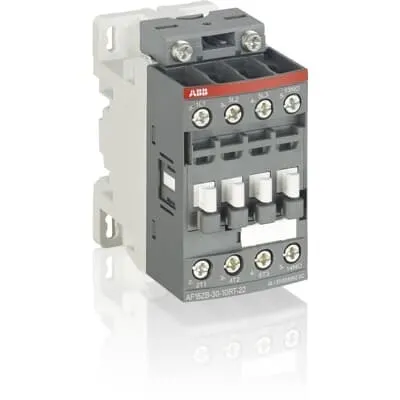
1SBL176060R2301 ABB: The AF16ZB-30-01RT-23 is a 3 pole - 690 V IEC or 600 UL contactor with 1 built-in auxiliary contact and Ring-Tongue Terminals, controlling motors up to 7.5 kW / 400 V AC (AC-3) or 10 hp / 480 V UL and switching power circuits up to 30 A (AC-1) or 30 A UL general use. Thanks to the AF technology, the contactor has a wide control voltage range (100-250 V 50/60 Hz and DC), managing large control voltage variations, reducing panel energy consumptions and ensuring distinct operations in unstable networks. Furthermore, surge protection is built-in, offering a compact solution. AF contactors have a block type design, can be easily extended with add-on auxiliary contact blocks and an additional wide range of accessories.
Minimum Order Quantity
1 piece
Customs Tariff Number
85364900
Data Sheet, Technical Information
Motor control and protection for Rolling stock application_PDF
Instructions and Manuals
Installation instructions AF09...38(Z)B-..RT Contactors, NF(Z)B..ERT Contactor relays and CA4..RT, CAL4..RT, CAT4..RT, LDC4RT Accessories
Instructions and Manuals (Part 2)
Contactors and Overload relays guide
CAD Dimensional Drawing
Information - 2D and 3D files for CAD systems
Product Net Width
45 mm
Product Net Depth / Length
77 mm
Product Net Height
86 mm
Product Net Weight
0.32 kg
Number of Main Contacts NO
3
Number of Main Contacts NC
0
Number of Auxiliary Contacts NO
0
Number of Auxiliary Contacts NC
1
Number of Poles
3P
Standards
IEC/EN 60947-1, IEC/EN 60947-4-1, UL 60947-4-1, CSA C22.2 No. 60947-4-1, IEC 60077-1 (applicable parts), IEC 60077-2 (applicable parts), EN 50155 (applicable parts), TR CU 001/2011, IEC 61373, For compliance confirmation on applicable parts based on your application and combination, please consult your ABB sales representatives.
Rated Operational Voltage
Auxiliary Circuit 690 V | Main Circuit 690 V
Rated Frequency (f)
Auxiliary Circuit 50 / 60 Hz | Control Circuit 50 / 60 Hz | Main Circuit 50 / 60 Hz
Conventional Free-air Thermal Current (Ith)
acc. to IEC 60947-4-1, Open Contactors Θ = 40 °C 35 A | acc. to IEC 60947-5-1, Θ = 40 °C 16 A
Rated Operational Current AC-1 (Ie)
(690 V) 40 °C 30 A | (690 V) 60 °C 30 A | (690 V) 70 °C 26 A
Rated Operational Current AC-3 (Ie)
(415 V) 60 °C 18 A | (440 V) 60 °C 18 A | (500 V) 60 °C 15 A | (690 V) 60 °C 10.5 A | (380 / 400 V) 60 °C 18 A | (220 / 230 / 240 V) 60 °C 18 A
Rated Operational Current AC-3e (Ie)
(415 V) 60 °C 18 A | (440 V) 60 °C 18 A | (500 V) 60 °C 15 A | (690 V) 60 °C 10.5 A | (380 / 400 V) 60 °C 18 A | (220 / 230 / 240 V) 60 °C 18 A
Rated Operational Current AC-15 (Ie)
(500 V) 2 A | (690 V) 2 A | (24 / 127 V) 6 A | (220 / 240 V) 4 A | (400 / 440 V) 3 A
Rated Operational Current DC-1 (Ie)
(110 V) 1-Pole, 40 °C 20 A | (110 V) 1-Pole, 60 °C 20 A | (110 V) 1-Pole, 70 °C 20 A | (110 V) 2 Poles in Series, 40 °C 30 A | (110 V) 2 Poles in Series, 60 °C 30 A | (110 V) 2 Poles in Series, 70 °C 26 A | (110 V) 3 Poles in Series, 40 °C 30 A | (110 V) 3 Poles in Series, 60 °C 30 A | (110 V) 3 Poles in Series, 70 °C 26 A | (220 V) 2 Poles in Series, 40 °C 20 A | (220 V) 2 Poles in Series, 60 °C 20 A | (220 V) 2 Poles in Series, 70 °C 20 A | (220 V) 3 Poles in Series, 40 °C 30 A | (220 V) 3 Poles in Series, 60 °C 30 A | (220 V) 3 Poles in Series, 70 °C 26 A | (72 V) 1-Pole, 40 °C 30 A | (72 V) 1-Pole, 60 °C 30 A | (72 V) 1-Pole, 70 °C 26 A | (72 V) 2 Poles in Series, 40 °C 30 A | (72 V) 2 Poles in Series, 60 °C 30 A | (72 V) 2 Poles in Series, 70 °C 26 A | (72 V) 3 Poles in Series, 40 °C 30 A | (72 V) 3 Poles in Series, 60 °C 30 A | (72 V) 3 Poles in Series, 70 °C 26 A
Rated Operational Current DC-3 (Ie)
(110 V) 1-Pole, 40 °C 8 A | (110 V) 1-Pole, 60 °C 8 A | (110 V) 1-Pole, 70 °C 8 A | (110 V) 2 Poles in Series, 40 °C 30 A | (110 V) 2 Poles in Series, 60 °C 30 A | (110 V) 2 Poles in Series, 70 °C 26 A | (110 V) 3 Poles in Series, 40 °C 30 A | (110 V) 3 Poles in Series, 60 °C 30 A | (110 V) 3 Poles in Series, 70 °C 26 A | (220 V) 2 Poles in Series, 40 °C 8 A | (220 V) 2 Poles in Series, 60 °C 8 A | (220 V) 2 Poles in Series, 70 °C 8 A | (220 V) 3 Poles in Series, 40 °C 30 A | (220 V) 3 Poles in Series, 60 °C 30 A | (220 V) 3 Poles in Series, 70 °C 26 A | (72 V) 1-Pole, 40 °C 30 A | (72 V) 1-Pole, 60 °C 30 A | (72 V) 1-Pole, 70 °C 26 A | (72 V) 2 Poles in Series, 40 °C 30 A | (72 V) 2 Poles in Series, 60 °C 30 A | (72 V) 2 Poles in Series, 70 °C 26 A | (72 V) 3 Poles in Series, 40 °C 30 A | (72 V) 3 Poles in Series, 60 °C 30 A | (72 V) 3 Poles in Series, 70 °C 26 A
Rated Operational Current DC-5 (Ie)
(110 V) 1-Pole, 40 °C 4 A | (110 V) 1-Pole, 60 °C 4 A | (110 V) 1-Pole, 70 °C 4 A | (110 V) 2 Poles in Series, 40 °C 20 A | (110 V) 2 Poles in Series, 60 °C 20 A | (110 V) 2 Poles in Series, 70 °C 20 A | (110 V) 3 Poles in Series, 40 °C 30 A | (110 V) 3 Poles in Series, 60 °C 30 A | (110 V) 3 Poles in Series, 70 °C 26 A | (220 V) 2 Poles in Series, 40 °C 4 A | (220 V) 2 Poles in Series, 60 °C 4 A | (220 V) 2 Poles in Series, 70 °C 4 A | (220 V) 3 Poles in Series, 40 °C 16 A | (220 V) 3 Poles in Series, 60 °C 16 A | (220 V) 3 Poles in Series, 70 °C 16 A | (72 V) 1-Pole, 40 °C 16 A | (72 V) 1-Pole, 60 °C 16 A | (72 V) 1-Pole, 70 °C 16 A | (72 V) 2 Poles in Series, 40 °C 30 A | (72 V) 2 Poles in Series, 60 °C 30 A | (72 V) 2 Poles in Series, 70 °C 26 A | (72 V) 3 Poles in Series, 40 °C 30 A | (72 V) 3 Poles in Series, 60 °C 30 A | (72 V) 3 Poles in Series, 70 °C 26 A
Rated Operational Current DC-13 (Ie)
(24 V) 6 A / 144 W | (48 V) 2.8 A / 134 W | (72 V) 1 A / 72 W | (110 V) 0.55 A / 60 W | (125 V) 0.55 A / 69 W | (220 V) 0.27 A / 60 W | (250 V) 0.27 A / 68 W | (400 V) 0.15 A / 60 W | (500 V) 0.13 A / 65 W | (600 V) 0.1 A / 60 W
Rated Operational Power AC-3 (Pe)
(415 V) 9 kW | (440 V) 9 kW | (500 V) 9 kW | (690 V) 9 kW | (380 / 400 V) 7.5 kW | (220 / 230 / 240 V) 4 kW
Rated Operational Power AC-3e (Pe)
(415 V) 9 kW | (440 V) 9 kW | (500 V) 9 kW | (690 V) 9 kW | (380 / 400 V) 7.5 kW | (220 / 230 / 240 V) 4 kW
Rated Short-time Withstand Current Low Voltage (Icw)
at 40 °C Ambient Temp, in Free Air, from a Cold State 10 s 150 A | at 40 °C Ambient Temp, in Free Air, from a Cold State 15 min 35 A | at 40 °C Ambient Temp, in Free Air, from a Cold State 1 min 60 A | at 40 °C Ambient Temp, in Free Air, from a Cold State 1 s 300 A | at 40 °C Ambient Temp, in Free Air, from a Cold State 30 s 80 A | for 0.1 s 140 A | for 1 s 100 A
Maximum Breaking Capacity
cos phi=0.45 (cos phi=0.35 for Ie > 100 A) at 440 V 250 A | cos phi=0.45 (cos phi=0.35 for Ie > 100 A) at 690 V 106 A
Rated Insulation Voltage (Ui)
acc. to IEC 60947-4-1 690 V | acc. to IEC 60947-5-1 690 V | acc. to UL/CSA 600 V
Rated Impulse Withstand Voltage (Uimp)
6 kV
Maximum Electrical Switching Frequency
(AC-1) 600 cycles per hour | (AC-15) 1200 cycles per hour | (AC-2 / AC-4) 300 cycles per hour | (AC-3) 1200 cycles per hour | (DC-13) 900 cycles per hour
Maximum Mechanical Switching Frequency
3600 cycles per hour
Rated Control Circuit Voltage (Uc)
50 Hz 100 ... 250 V | 60 Hz 100 ... 250 V | DC Operation 100 ... 250 V
Power Loss
at 6 A per Pole 0.1 W | at Rated Operating Conditions AC-1 per Pole 1.2 W | at Rated Operating Conditions AC-3 per Pole 0.35 W
Operate Time
Between Coil De-energization and NC Contact Closing 13 ... 98 ms | Between Coil De-energization and NO Contact Opening 11 ... 95 ms | Between Coil Energization and NC Contact Opening 38 ... 90 ms | Between Coil Energization and NO Contact Closing 40 ... 95 ms
Mounting on DIN Rail
TH35-15 (35 x 15 mm Mounting Rail) acc. to IEC 60715 | TH35-7.5 (35 x 7.5 mm Mounting Rail) acc. to IEC 60715
Mounting by Screws (not supplied)
2 x M4 screws placed diagonally
Degree of Protection
acc. to IEC 60529, IEC 60947-1, EN 60529 Auxiliary Terminals IP10 | acc. to IEC 60529, IEC 60947-1, EN 60529 Coil Terminals IP10 | acc. to IEC 60529, IEC 60947-1, EN 60529 Main Terminals IP10
Tightening Torque
Auxiliary Circuit 1.2 N·m | Control Circuit 1.2 N·m | Main Circuit 1.5 N·m
Terminal Type
Ring-Tongue Terminals
Product Name
Block Contactor
Maximum Operating Voltage UL/CSA
Main Circuit 600 V
General Use Rating UL/CSA
(600 V AC) 30 A
Horsepower Rating UL/CSA
(120 V AC) Single Phase 1-1/2 hp | (200 ... 208 V AC) Three Phase 5 hp | (220 ... 240 V AC) Three Phase 5 hp | (240 V AC) Single Phase 3 hp | (440 ... 480 V AC) Three Phase 10 hp | (550 ... 600 V AC) Three Phase 15 hp
Tightening Torque UL/CSA
Auxiliary Circuit 11 in·lb | Control Circuit 11 in·lb | Main Circuit 13 in·lb
Full Load Amps Motor Use
(120 V AC) Single Phase 20 A | (200 ... 208 V AC) Three Phase 17.5 A | (220 ... 240 V AC) Three Phase 15.2 A | (240 V AC) Single Phase 17 A | (440 ... 480 V AC) Three Phase 14 A | (550 ... 600 V AC) Three Phase 17 A
Ambient Air Temperature
Close to Contactor Fitted with Thermal O/L Relay -25 ... 60 °C | Close to Contactor without Thermal O/L Relay -40 ... 70 °C | Close to Contactor for Storage -60 ... +80 °C
Climatic Withstand
Category B according to IEC 60947-1 Annex Q
Maximum Operating Altitude Permissible
Without Derating 3000 m
Shock and Vibration Withstand acc. to IEC 61373
Category 1, Class B
Pollution Degree
3
Conflict Minerals Reporting Template (CMRT)
CMRT - Conflict Minerals Reporting Template
REACH Declaration
REACH - Letter of Confirmation for block contactors, contactor relays, installation contactors, mini contactors, mini contactor relays, thermal overload relays, electronic overload relays and related accessories
RoHS Information
RoHS II declaration for block contactors, installation contactors, mini contactors, mini contactor relays, thermal overload relays, electronic overload relays and related accessories
RoHS Status
Following EU Directive 2011/65/EU and Amendment 2015/863 July 22, 2019
Toxic Substances Control Act - TSCA
Toxic Substances Control Act (TSCA) declaration for Contactors
WEEE B2C / B2B
Business To Business
WEEE Category
5. Small Equipment (No External Dimension More Than 50 cm)
End Of Life Disassembling Instructions
End of life instruction AF(S)09/12/16/26/30/38(Z)(B)(K)(RT) Contactors & NF(Z)(B)(K)(RT) Contactors relays
Environmental Product Declaration - EPD
Environmental Product Declaration - AF09/12/16(Z)(B) Contactors and NF(Z) Contactor relaysAF(S)09/12/16(Z)(B) Contactors and NF(Z)(B) Contactors Relays (FR) | Environmental Product Declaration - AF09/12/16(Z)(B) Contactors and NF(Z) Contactor relays
Sustainable Material Content in Packaging (wt. %)
Recycled Cardboard - 86 %
Sustainable Material Content in Product (wt. %)
Recycled Metal - 28 %
CB Certificate
CB Certificate AF09, AF12, AF16, AF09(Z)B, AF12(Z)B, AF16(Z)B 3 and 4-pole contactors, AFS09, AFS12, AFS16 safety contactors
CCC Certificate
CCC Certificate AF09, AF12, AF16, AF09(Z)B, AF12(Z)B, AF16(Z)B 3 and 4-pole contactors, AFS09, AFS12, AFS16 safety contactors
CQC Certificate
CQC Certificate AF(C)09, AF(C)12, AF(C)16, AF09(Z)B, AF12(Z)B, AF16(Z)B 3 and 4-pole contactors, AFS09, AFS12, AFS16 safety contactors
Declaration of Conformity - CCC
CCC Declaration of Conformity, Contactor, AF*09, AF*12, AF*16, Made in France
Declaration of Conformity - CE
EU Declaration of Conformity AF09 to AF38(Z)B..RT 3 and 4-pole contactors
Declaration of Conformity - UKCA
UK Declaration of Conformity AF09 to AF38(Z)B..RT 3 and 4-pole contactors
UL Listing Card
UL_E312527
UR Certificate
UR Certificate of Compliance AF09...AF38(Z)B..RT 3-pole contactors with ring tongue terminals
Package Level 1 Units
box 1 piece
Package Level 1 Width
87 mm
Package Level 1 Depth / Length
79 mm
Package Level 1 Height
47 mm
Package Level 1 Gross Weight
0.32 kg
Package Level 1 EAN
3471523128330
Package Level 2 Units
box 27 piece
Package Level 2 Width
250 mm
Package Level 2 Depth / Length
300 mm
Package Level 2 Height
315 mm
Package Level 2 Gross Weight
17.28 kg
Package Level 3 Units
1296 piece
Object Classification Code
Q
ETIM 7
EC000066 - Power contactor, AC switching
ETIM 8
EC000066 - Power contactor, AC switching
ETIM 9
EC000066 - Power contactor, AC switching
eClass
V11.0 : 27371003
UNSPSC
39121529
IDEA Granular Category Code (IGCC)
4758 >> Iec Contactors
AF technology provides a wide control voltage range of 100–250 VAC or DC, enabling operation across fluctuating networks and reducing energy consumption in the control circuit. This translates to lower panel heat and improved system reliability in variable-power environments, which is especially valuable in remote or.indexed automation installations. The built-in surge protection further reduces the need for external protection devices, cutting component counts and installation time while enhancing overall system robustness. The 3-pole main circuit rated for up to 690 V supports AC-1 and AC-3 operations with 30 A and 10.5 A respectively, enabling motors up to 9 kW at higher voltages, with power ratings clearly defined for common industrial configurations. An integrated NO/NC auxiliary contact provides signaling and interlock options without adding extra relays, improving control logic clarity and fault detection. The Ring-Tongue terminals simplify wiring, ensuring reliable connections and faster commissioning. DIN-rail mounting on TH35-15 or TH35-7.5, plus 2 x M4 mounting screws, reduces installation time and improves vibration resistance in dynamic applications. Dimensions (45 mm W × 77 mm D × 86 mm H) and a light 0.32 kg weight make it ideal for compact control panels. Compatibility with add-on auxiliary contact blocks and ABB accessory range supports scalable automation strategies as requirements evolve. The device meets multiple standards (IEC/EN 60947-1, IEC 60947-4-1, UL 60947-4-1) and RoHS/REACH/WEEE commitments, giving peace of mind for global deployments and long lifecycle planning. Operational temperatures range from -25 to 60 °C with thermal overload relay installed, extending service life in harsh environments, while the compact form factor helps minimize cabinet footprint and wiring complexity in mass-produced panels.
Get a Quick Quote for a ABB 1SBL176060R2301
Chat with us on WhatsApp - fast responses guaranteed
Need to speak with someone? We'll call you back within 2 hours during business hours
Interested in ABB 1SBL176060R2301?
Enquire Now
FAQs
Mount the device on a standard TH35 DIN rail (TH35-15 or TH35-7.5) and secure with the two diagonal M4 screws. Wire the coil to the 100–250 V control circuit (AC or DC) using Ring-Tongue terminals, and connect the main and auxiliary contacts as required. Ensure IP10 protection and verify tightening torques per specifications.
At 690 V, the contactor provides AC-1 current up to 30 A and AC-3 current up to 10.5 A. Rated power in AC-3 is up to 9 kW (415–690 V). The device supports 50/60 Hz operation and a coil voltage range of 100–250 V (AC or DC), enabling reliable switching across common industrial networks.
Yes. ABB documents this model within the AF family for motor control in rolling stock contexts, with applicable references to EN 50155 and related parts. For rail applications, verify the exact part combination with ABB to ensure full compliance, safety interlocks, and suitability in your specific vehicle or subsystem.
Certifications include CE and UKCA declarations, UL/CSA listings, UR certificate, CCC, CQC, CB Certificate, RoHS 2, REACH, and WEEE considerations for B2B. ABB provides related DoC and conformity documentation; confirm market-specific requirements with ABB for your deployment region.
AF technology tolerates wide control voltage variations, reducing energy waste and panel heat. Built-in surge protection lowers external protection needs, decreasing components and maintenance, while the compact, modular design supports scalable automation and quicker servicing. These factors contribute to lower total cost of ownership across automated lines and distributed control systems.