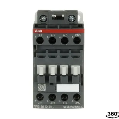
ABB 1SBL177087R1310 Block Contactor - UL A2L
Part Number: 1SBL177087R1310
Quick Summary
ABB block contactor AF16-30-10-13LU is designed to switch motors and UL lighting loads with a wide 100–250 V control range. In networks with voltage fluctuations, traditional controllers can misfire or stall, but this device tolerates large control voltage variations while delivering reliable operation. It complies with IEC/EN 60947-4-1 and 60947-1, and carries UL 60335-2-40 LZGH2 A2L and CSA listings, with CE and UKCA declarations for global deployment. The compact 3P design is DIN-rail compatible and easily expandable with add-on auxiliary blocks, delivering efficiency and scalability for modern control panels. Designed for steady performance in demanding environments, it also features low power loss per coil and built-in surge protection for long-term reliability.
Product Information
Extended Description
1SBL177087R1310 ABB: The AF16-30-10-13LUdedicated for UL lighting applications. Thanks to the AF technology, the contactor has a wide control voltage range (100-250 V 50/60 Hz and DC),managing large control voltage variations, reducing panel energy consumptions and ensuring distinct operations in unstable networks. Furthermore, surge protection is built-in, offering a compact solution. AF contactors have a block type design, can be easily extended with add-on auxiliary contact blocks and an additional wide range of accessories.
Minimum Order Quantity
1 piece
Data Sheet, Technical Information
1SBC100214C0202 - Main catalog Motor protection and control Manual motor starters, contactors and overload relays (PDF) - Edition 2024
Instructions and Manuals
Installation instructions AF(C)09...38(Z)(B) Contactors, NF(C)(Z)(B)22...80E Contactor relays and CA4, CAL4, CAT4, CC4, LDC4 Accessories
Instructions and Manuals (Part 2)
Contactors and Overload relays guide
CAD Dimensional Drawing
Information - 2D and 3D files for CAD systems
Product Net Width
45 mm
Product Net Depth / Length
77 mm
Product Net Height
86 mm
Product Net Weight
0.27 kg
Number of Main Contacts NO
3
Number of Main Contacts NC
0
Number of Auxiliary Contacts NO
1
Number of Auxiliary Contacts NC
0
Number of Poles
3P
Standards
IEC/EN 60947-1, IEC/EN 60947-4-1, UL 60335-2-40 LZGH2 A2L, UL 60947-4-1, CSA C22.2 No. 60335-2-40 LZGH2 A2L, CSA C22.2 No. 60947-4-1
Rated Operational Voltage
Auxiliary Circuit 690 V | Main Circuit 690 V
Rated Frequency (f)
Auxiliary Circuit 50 / 60 Hz | Control Circuit 50 / 60 Hz | Main Circuit 50 / 60 Hz
Conventional Free-air Thermal Current (Ith)
acc. to IEC 60947-4-1, Open Contactors Θ = 40 °C 35 A | acc. to IEC 60947-5-1, Θ = 40 °C 16 A
Rated Operational Current AC-1 (Ie)
(690 V) 40 °C 30 A | (690 V) 60 °C 30 A | (690 V) 70 °C 26 A
Rated Operational Current AC-3 (Ie)
(415 V) 60 °C 18 A | (440 V) 60 °C 18 A | (500 V) 60 °C 15 A | (690 V) 60 °C 10.5 A | (380 / 400 V) 60 °C 18 A | (220 / 230 / 240 V) 60 °C 18 A
Rated Operational Current AC-3e (Ie)
(415 V) 60 °C 18 A | (440 V) 60 °C 18 A | (500 V) 60 °C 15 A | (690 V) 60 °C 10.5 A | (380 / 400 V) 60 °C 18 A | (220 / 230 / 240 V) 60 °C 18 A
Rated Operational Current AC-15 (Ie)
(500 V) 2 A | (690 V) 2 A | (24 / 127 V) 6 A | (220 / 240 V) 4 A | (400 / 440 V) 3 A
Rated Operational Current DC-13 (Ie)
(24 V) 6 A / 144 W | (48 V) 2.8 A / 134 W | (72 V) 1 A / 72 W | (110 V) 0.55 A / 60 W | (125 V) 0.55 A / 69 W | (220 V) 0.27 A / 60 W | (250 V) 0.27 A / 68 W | (400 V) 0.15 A / 60 W | (500 V) 0.13 A / 65 W | (600 V) 0.1 A / 60 W
Rated Operational Power AC-3 (Pe)
(400 V) 7.5 kW | (415 V) 9 kW | (440 V) 9 kW | (500 V) 9 kW | (690 V) 9 kW | (380 / 400 V) 7.5 kW | (220 / 230 / 240 V) 4 kW
Rated Operational Power AC-3e (Pe)
(415 V) 9 kW | (440 V) 9 kW | (500 V) 9 kW | (690 V) 9 kW | (380 / 400 V) 7.5 kW | (220 / 230 / 240 V) 4 kW
Rated Short-time Withstand Current Low Voltage (Icw)
at 40 °C Ambient Temp, in Free Air, from a Cold State 10 s 150 A | at 40 °C Ambient Temp, in Free Air, from a Cold State 15 min 35 A | at 40 °C Ambient Temp, in Free Air, from a Cold State 1 min 60 A | at 40 °C Ambient Temp, in Free Air, from a Cold State 1 s 300 A | at 40 °C Ambient Temp, in Free Air, from a Cold State 30 s 80 A | for 0.1 s 140 A | for 1 s 100 A
Maximum Breaking Capacity
cos phi=0.45 (cos phi=0.35 for Ie > 100 A) at 440 V 250 A | cos phi=0.45 (cos phi=0.35 for Ie > 100 A) at 690 V 106 A
Rated Insulation Voltage (Ui)
acc. to IEC 60947-4-1 690 V | acc. to IEC 60947-5-1 690 V | acc. to UL/CSA 600 V
Rated Impulse Withstand Voltage (Uimp)
6 kV
Maximum Electrical Switching Frequency
(AC-1) 600 cycles per hour | (AC-15) 1200 cycles per hour | (AC-2 / AC-4) 300 cycles per hour | (AC-3) 1200 cycles per hour | (DC-13) 900 cycles per hour
Maximum Mechanical Switching Frequency
3600 cycles per hour
Rated Control Circuit Voltage (Uc)
50 Hz 100 ... 250 V | 60 Hz 100 ... 250 V | DC Operation 100 ... 250 V
Power Loss
at 6 A per Pole 0.1 W | at Rated Operating Conditions AC-1 per Pole 1.2 W | at Rated Operating Conditions AC-3 per Pole 0.35 W
Operate Time
Between Coil De-energization and NC Contact Closing 13 ... 98 ms | Between Coil De-energization and NO Contact Opening 11 ... 95 ms | Between Coil Energization and NC Contact Opening 38 ... 90 ms | Between Coil Energization and NO Contact Closing 40 ... 95 ms
Mounting on DIN Rail
TH35-15 (35 x 15 mm Mounting Rail) acc. to IEC 60715 | TH35-7.5 (35 x 7.5 mm Mounting Rail) acc. to IEC 60715
Mounting by Screws (not supplied)
2 x M4 screws placed diagonally
Connecting Capacity Main Circuit
Flexible with Ferrule 1/2x 0.75 ... 6 mm² | Flexible with Insulated Ferrule 1x 0.75 ... 4 mm² | Flexible with Insulated Ferrule 2x 0.75 ... 2.5 mm² | Rigid Solid 1/2x 1 ... 4 mm² | Rigid Stranded 1/2x 1 ... 6 mm²
Connecting Capacity Auxiliary Circuit
Flexible with Ferrule 1/2x 0.75 ... 2.5 mm² | Flexible with Insulated Ferrule 2x 0.75 ... 1.5 mm² | Flexible with Insulated Ferrule 1/2x 0.75 ... 1.5 mm² | Rigid Solid 1/2x 1 ... 2.5 mm² | Rigid Stranded 1/2x 1 ... 2.5 mm²
Connecting Capacity Control Circuit
Flexible with Ferrule 1/2x 0.75 ... 2.5 mm² | Flexible with Insulated Ferrule 1x 0.75 ... 2.5 mm² | Flexible with Insulated Ferrule 2x 0.75 ... 1.5 mm² | Rigid Solid 1/2x 1 ... 2.5 mm² | Rigid Stranded 1/2x 1 ... 2.5 mm²
Wire Stripping Length
Auxiliary Circuit 10 mm | Control Circuit 10 mm | Main Circuit 10 mm
Degree of Protection
acc. to IEC 60529, IEC 60947-1, EN 60529 Auxiliary Terminals IP20 | acc. to IEC 60529, IEC 60947-1, EN 60529 Coil Terminals IP20 | acc. to IEC 60529, IEC 60947-1, EN 60529 Main Terminals IP20
Tightening Torque
Auxiliary Circuit 1.2 N·m | Control Circuit 1.2 N·m | Main Circuit 1.5 N·m
Terminal Type
Screw Terminals
Product Name
Block Contactor
Maximum Operating Voltage UL/CSA
Main Circuit 600 V
General Use Rating UL/CSA
(600 V AC) 30 A
Horsepower Rating UL/CSA
(120 V AC) Single Phase 1-1/2 hp | (200 ... 208 V AC) Three Phase 5 hp | (220 ... 240 V AC) Three Phase 5 hp | (240 V AC) Single Phase 3 hp | (440 ... 480 V AC) Three Phase 10 hp | (550 ... 600 V AC) Three Phase 15 hp
Connecting Capacity Main Circuit UL/CSA
Rigid Solid 1/2x 16-10 AWG | Rigid Stranded 1/2x 16-10 AWG
Connecting Capacity Auxiliary Circuit UL/CSA
Rigid Solid 1/2x 18-14 AWG | Rigid Stranded 1/2x 18-14 AWG
Connecting Capacity Control Circuit UL/CSA
Rigid Solid 1/2x 18-14 AWG | Rigid Stranded 1/2x 18-14 AWG
Tightening Torque UL/CSA
Auxiliary Circuit 11 in·lb | Control Circuit 11 in·lb | Main Circuit 13 in·lb
Full Load Amps Motor Use
(120 V AC) Single Phase 20 A | (200 ... 208 V AC) Three Phase 17.5 A | (220 ... 240 V AC) Three Phase 15.2 A | (240 V AC) Single Phase 17 A | (440 ... 480 V AC) Three Phase 14 A | (550 ... 600 V AC) Three Phase 17 A
Ambient Air Temperature
Close to Contactor Fitted with Thermal O/L Relay -25 ... 60 °C | Close to Contactor without Thermal O/L Relay -40 ... 70 °C | Close to Contactor for Storage -60 ... +80 °C
Climatic Withstand
Category B according to IEC 60947-1 Annex Q
Maximum Operating Altitude Permissible
Without Derating 3000 m
Resistance to Shock acc. to IEC 60068-2-27
Closed, Shock Direction: B1 25 g | Open, Shock Direction: B1 5 g | Shock Direction: A 30 g | Shock Direction: B2 15 g | Shock Direction: C1 25 g | Shock Direction: C2 25 g
Resistance to Vibrations
4g Closed Position & 2g Open position 5 ... 300 Hz
Pollution Degree
3
Conflict Minerals Reporting Template (CMRT)
CMRT - Conflict Minerals Reporting Template
REACH Declaration
REACH - Letter of Confirmation for block contactors, contactor relays, installation contactors, mini contactors, mini contactor relays, thermal overload relays, electronic overload relays and related accessories
RoHS Information
RoHS II declaration for block contactors, installation contactors, mini contactors, mini contactor relays, thermal overload relays, electronic overload relays and related accessories
RoHS Status
Following EU Directive 2011/65/EU and Amendment 2015/863 July 22, 2019
Toxic Substances Control Act - TSCA
Toxic Substances Control Act (TSCA) declaration for Contactors
WEEE B2C / B2B
Business To Business
WEEE Category
5. Small Equipment (No External Dimension More Than 50 cm)
End Of Life Disassembling Instructions
End of life instruction AF(S)09/12/16/26/30/38(Z)(B)(K)(RT) Contactors & NF(Z)(B)(K)(RT) Contactors relays
Sustainable Material Content in Packaging (wt. %)
Recycled Cardboard - 86 %
Sustainable Material Content in Product (wt. %)
Recycled Metal - 28 %
A2L Certificate – UL
UL-US A2L LZGH2 Certificate of Compliance AF09 ... AF38 3-pole contactors with screw terminals - UL 60335-2-40 Household and Similar Electrical Appliances - Safety - Part 2-40: Particular Requirements for Electrical Heat Pumps, Air-Conditioners and Dehumidifiers | UL-CA A2L LZGH2 Certificate of Compliance AF09 ... AF38 3-pole contactors with screw terminals - CSA C22.2 No. 60335-2-40 Household and Similar Electrical Appliances - Safety - Part 2-40: Particular Requirements for Electrical Heat Pumps, Air-Conditioners and Dehumidifiers
CB Certificate
CB Certificate AF09, AF12, AF16, AF09(Z)B, AF12(Z)B, AF16(Z)B 3 and 4-pole contactors, AFS09, AFS12, AFS16 safety contactors
Declaration of Conformity - CE
EU Declaration of Conformity AF09..LU ... AF80..LU 3 and 4-pole contactors
Declaration of Conformity - UKCA
UK Declaration of Conformity AF09..LU ... AF80..LU 3 and 4-pole contactors
UL Certificate
UL-US Certificate of Compliance AF(C)(S)09(R/M/N)-..(L)(S)(K)...AF(C)(S)38(R/M/N)..(K) 3-pole contactors screw, spring and push-in spring terminals; LDC4 additional coil terminal block; LF16-4, LG16-4, LF38-4 and LH38-4 connecting strips, LD38-4 additional terminal block | UL-CA Certificate of Compliance AF(C)(S)09(R/M/N)-..(L)(S)(K)...AF(C)(S)38(R/M/N)..(K) 3-pole contactors screw, spring and push-in spring terminals; LDC4 additional coil terminal block; LF16-4, LG16-4, LF38-4 and LH38-4 connecting strips, LD38-4 additional terminal block
Package Level 1 Units
box 1 piece
Package Level 1 Width
87 mm
Package Level 1 Depth / Length
79 mm
Package Level 1 Height
47 mm
Package Level 1 Gross Weight
0.27 kg
Package Level 1 EAN
3471523020573
Package Level 2 Units
box 27 piece
Package Level 2 Width
250 mm
Package Level 2 Depth / Length
300 mm
Package Level 2 Height
315 mm
Package Level 2 Gross Weight
7.29 kg
Package Level 3 Units
1296 piece
Object Classification Code
Q
ETIM 7
EC000066 - Power contactor, AC switching
ETIM 8
EC000066 - Power contactor, AC switching
ETIM 9
EC000066 - Power contactor, AC switching
eClass
V11.0 : 27371003
UNSPSC
39121529
IDEA Granular Category Code (IGCC)
4760 >> Lighting Contactors
Feature: Wide control voltage range. Business Impact: Reduces panel wiring variations and energy waste by tolerating 100–250 V AC/50/60 Hz and DC control signals. Application: Ideal for panel builders and OEMs integrating machines with fluctuating supply; complements AF technology for stable operation across sites. Feature: Built-in surge protection. Business Impact: Extends coil life and reduces maintenance by mitigating voltage spikes common in UL lighting applications. Application: Essential in conveyor, pump, and HVAC drives where voltage transients are frequent. Feature: 3P main, 3 NO + 1 NO auxiliary contacts. Business Impact: Enables reliable motor control with feedback and interlocking options, reducing miswiring and improving control logic. Application: Suitable for multi-motor and line-start applications in assembly and packaging lines. Feature: DIN rail mounting and compact form. Business Impact: Speedy installation and easy retrofits in standard control cabinets; saves panel space with 45 mm width and 86 mm height. Application: Ideal for modern machine builds and retrofit projects. Feature: High voltage ratings and energy efficiency. Business Impact: Supports 690 V main circuits with low per-pole power loss (0.1–1.2 W depending on mode), improving overall energy efficiency. Application: Suitable for European and North American equipment using AC-3/AC-1 duty cycles. Feature: Expandability and compliance support. Business Impact: Add-on auxiliary contact blocks extend functionality without replacing the actuator; certifications (IEC, UL, CSA, CE, UKCA) help ensure regulatory alignment. Application: Fits into certified control panels and equipment requiring robust protection and traceability.
Get a Quick Quote for a ABB 1SBL177087R1310
Chat with us on WhatsApp - fast responses guaranteed
Need to speak with someone? We'll call you back within 2 hours during business hours
Interested in ABB 1SBL177087R1310?
Enquire Now
FAQs
The AF16-30-10-13LU is designed for DIN rail mounting on TH35-15 and TH35-7.5 rails, enabling quick integration into standard control panels. If you need wall mounting, 2 x M4 screws can secure the unit diagonally. This flexibility minimizes cabinet redesigns during retrofits and supports compact, organized panel layouts.
This is a 3-pole device with 3 NO main contacts and 1 NO auxiliary contact. Main circuit rated up to 690 V with AC-1, AC-3, and AC-3e operating modes; auxiliary and control circuits rated up to 690 V. Control voltage is 100–250 V AC/50/60 Hz or DC, with coil power loss specified per operating conditions.
Yes. It is engineered for 3-pole, 690 V systems and UL/CSA listings, with compatibility for motor protection and control tasks in lighting and machinery. The device supports standard IEC 60947-4-1/60947-1 and UL 60335-2-40 environments, making it suitable for UL-listed panels and compliant installations.
The product complies with IEC/EN 60947-1, IEC/EN 60947-4-1, UL 60335-2-40 LZGH2 A2L, CSA C22.2 No. 60335-2-40, and carries CE and UKCA declarations. It also aligns with RoHS/REACH requirements and UL/CSA confirmations for global distribution and safe operation in commercial and industrial equipment.
Long-term reliability comes from built-in surge protection and wide control voltage tolerance, reducing nuisance trips and panel energy waste. Low coil power consumption (0.1–1.2 W per pole) minimizes heat generation and cooling needs, while its compact design saves cabinet space and simplifies retrofits, delivering lower lifecycle costs and improved machine uptime.