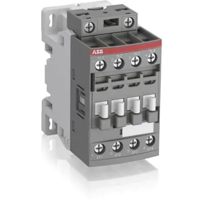
ABB AF16-40-00L-13 Block Contactor - IEC 60947-4-1
Part Number: 1SBL177281R1300
Quick Summary
ABB AF16-40-00L-13 Block Contactor is a four‑pole motor controller designed for 690 V main circuits in industrial drives. Engineers often face voltage swings and tripping due to unreliable networks; this model’s broad control voltage range (100–250 V AC/DC, 50/60 Hz) stabilizes coil energization and reduces panel energy waste. The device is built to IEC/EN 60947-4-1 and UL 60335-2-40 standards, with UL 508 and CSA recognition for wider market access. Its compact AF block design, built‑in surge protection, and easy expansion with add‑on auxiliary contacts simplify panel layouts and maintenance, while preserving a small footprint. For procurement teams, total cost of ownership is improved through reliability, reduced wiring complexity, and scalable control options.
Product Information
Extended Description
1SBL177281R1300 ABB: The AF16-40-00L-13 is a 4 pole - 690 V IEC or 600 UL contactor with screw terminals, controlling motors up to 7.5 kW / 400 V AC (AC-3) and switching power circuits up to 30 A (AC-1) or 30 A UL general use. Thanks to the AF technology, the contactor has a wide control voltage range (100-250 V 50/60 Hz and DC), managing large control voltage variations, reducing panel energy consumptions and ensuring distinct operations in unstable networks. Furthermore, surge protection is built-in, offering a compact solution. AF contactors have a block type design, can be easily extended with add-on auxiliary contact blocks and an additional wide range of accessories.
Minimum Order Quantity
1 piece
Data Sheet, Technical Information
Greenhouses application – lamp starting solution
Instructions and Manuals
Installation instructions AF(C)09...38(Z)(B) Contactors, NF(C)(Z)(B)22...80E Contactor relays and CA4, CAL4, CAT4, CC4, LDC4 Accessories
Instructions and Manuals (Part 2)
Contactors and Overload relays guide
CAD Dimensional Drawing
Information - 2D and 3D files for CAD systems
Product Net Width
45 mm
Product Net Depth / Length
77 mm
Product Net Height
86 mm
Product Net Weight
0.27 kg
Number of Main Contacts NO
4
Number of Main Contacts NC
0
Number of Auxiliary Contacts NO
0
Number of Auxiliary Contacts NC
0
Number of Poles
4P
Standards
IEC/EN 60947-1, IEC/EN 60947-4-1, UL 60335-2-40 LZGH2 A2L, UL 508, CSA C22.2 No. 60335-2-40 LZGH2 A2L, CSA C22.2 No. 60947-4-1
Rated Operational Voltage
Main Circuit 690 V
Rated Frequency (f)
Control Circuit 50 / 60 Hz | Main Circuit 50 / 60 Hz
Conventional Free-air Thermal Current (Ith)
acc. to IEC 60947-4-1, Open Contactors Θ = 40 °C 35 A
Rated Operational Current AC-1 (Ie)
(690 V) 40 °C 30 A | (690 V) 60 °C 30 A | (690 V) 70 °C 26 A
Rated Short-time Withstand Current Low Voltage (Icw)
at 40 °C Ambient Temp, in Free Air, from a Cold State 10 s 150 A | at 40 °C Ambient Temp, in Free Air, from a Cold State 15 min 35 A | at 40 °C Ambient Temp, in Free Air, from a Cold State 1 min 60 A | at 40 °C Ambient Temp, in Free Air, from a Cold State 1 s 300 A | at 40 °C Ambient Temp, in Free Air, from a Cold State 30 s 80 A
Maximum Breaking Capacity
cos phi=0.45 (cos phi=0.35 for Ie > 100 A) at 440 V 250 A | cos phi=0.45 (cos phi=0.35 for Ie > 100 A) at 690 V 106 A
Rated Insulation Voltage (Ui)
acc. to IEC 60947-4-1 690 V | acc. to UL/CSA 600 V
Rated Impulse Withstand Voltage (Uimp)
6 kV
Maximum Electrical Switching Frequency
(AC-1) 600 cycles per hour
Maximum Mechanical Switching Frequency
3600 cycles per hour
Rated Control Circuit Voltage (Uc)
50 Hz 100 ... 250 V | 60 Hz 100 ... 250 V | DC Operation 100 ... 250 V
Power Loss
0 W | at Rated Operating Conditions AC-1 per Pole 1.2 W | at Rated Operating Conditions AC-3 per Pole 0.35 W
Operate Time
Between Coil De-energization and NC Contact Closing 13 ... 98 ms | Between Coil De-energization and NO Contact Opening 11 ... 95 ms | Between Coil Energization and NC Contact Opening 38 ... 90 ms | Between Coil Energization and NO Contact Closing 40 ... 95 ms
Mounting on DIN Rail
TH35-15 (35 x 15 mm Mounting Rail) acc. to IEC 60715 | TH35-7.5 (35 x 7.5 mm Mounting Rail) acc. to IEC 60715
Mounting by Screws (not supplied)
2 x M4 screws placed diagonally
Connecting Capacity Main Circuit
Flexible with Ferrule 1/2x 0.75 ... 6 mm² | Flexible with Insulated Ferrule 1x 0.75 ... 4 mm² | Flexible with Insulated Ferrule 2x 0.75 ... 2.5 mm² | Rigid Solid 1/2x 1 ... 4 mm² | Rigid Stranded 1/2x 1 ... 6 mm²
Connecting Capacity Auxiliary Circuit
Rigid Solid 1/2x 1 ... 2.5 mm² | Rigid Stranded 1/2x 1 ... 2.5 mm²
Connecting Capacity Control Circuit
Flexible with Ferrule 1/2x 0.75 ... 2.5 mm² | Flexible with Insulated Ferrule 1x 0.75 ... 2.5 mm² | Flexible with Insulated Ferrule 2x 0.75 ... 1.5 mm² | Rigid Solid 1/2x 1 ... 2.5 mm² | Rigid Stranded 1/2x 1 ... 2.5 mm²
Wire Stripping Length
Control Circuit 10 mm | Main Circuit 10 mm
Degree of Protection
acc. to IEC 60529, IEC 60947-1, EN 60529 Coil Terminals IP20 | acc. to IEC 60529, IEC 60947-1, EN 60529 Main Terminals IP20
Tightening Torque
Control Circuit 1.2 N·m | Main Circuit 1.5 N·m
Terminal Type
Screw Terminals
Product Name
Block Contactor
Maximum Operating Voltage UL/CSA
Main Circuit 600 V
General Use Rating UL/CSA
(600 V AC) 30 A
Connecting Capacity Main Circuit UL/CSA
Rigid Solid 1/2x 16-10 AWG | Rigid Stranded 1/2x 16-10 AWG
Connecting Capacity Auxiliary Circuit UL/CSA
Rigid Solid 1/2x 18-14 AWG | Rigid Stranded 1/2x 18-14 AWG
Connecting Capacity Control Circuit UL/CSA
Rigid Solid 1/2x 18-14 AWG | Rigid Stranded 1/2x 18-14 AWG
Tightening Torque UL/CSA
Control Circuit 11 in·lb | Main Circuit 13 in·lb
Ambient Air Temperature
Close to Contactor for Storage -60 ... +80 °C | Near Contactor for Operation in Free Air -40 ... 70 °C
Climatic Withstand
Category B according to IEC 60947-1 Annex Q
Maximum Operating Altitude Permissible
Without Derating 3000 m
Resistance to Shock acc. to IEC 60068-2-27
Closed, Shock Direction: B1 25 g | Open, Shock Direction: B1 5 g | Shock Direction: A 30 g | Shock Direction: B2 15 g | Shock Direction: C1 25 g | Shock Direction: C2 25 g
Resistance to Vibrations
4g Closed Position & 2g Open position 5 ... 300 Hz
Pollution Degree
3
Conflict Minerals Reporting Template (CMRT)
CMRT - Conflict Minerals Reporting Template
REACH Declaration
REACH - Letter of Confirmation for block contactors, contactor relays, installation contactors, mini contactors, mini contactor relays, thermal overload relays, electronic overload relays and related accessories
RoHS Information
RoHS II declaration for block contactors, installation contactors, mini contactors, mini contactor relays, thermal overload relays, electronic overload relays and related accessories
RoHS Status
Following EU Directive 2011/65/EU and Amendment 2015/863 July 22, 2019
Toxic Substances Control Act - TSCA
Toxic Substances Control Act (TSCA) declaration for Contactors
WEEE B2C / B2B
Business To Business
WEEE Category
5. Small Equipment (No External Dimension More Than 50 cm)
End Of Life Disassembling Instructions
End of life instruction AF(S)09/12/16/26/30/38(Z)(B)(K)(RT) Contactors & NF(Z)(B)(K)(RT) Contactors relays
Sustainable Material Content in Packaging (wt. %)
Recycled Cardboard - 86 %
Sustainable Material Content in Product (wt. %)
Recycled Metal - 28 %
A2L Certificate – UL
UL-US A2L LZGH2 Certificate of Compliance AF09 ... AF38 3-pole contactors with screw terminals - UL 60335-2-40 Household and Similar Electrical Appliances - Safety - Part 2-40: Particular Requirements for Electrical Heat Pumps, Air-Conditioners and Dehumidifiers | UL-CA A2L LZGH2 Certificate of Compliance AF09 ... AF38 3-pole contactors with screw terminals - CSA C22.2 No. 60335-2-40 Household and Similar Electrical Appliances - Safety - Part 2-40: Particular Requirements for Electrical Heat Pumps, Air-Conditioners and Dehumidifiers
CB Certificate
CB Certificate AF09, AF12, AF16, AF09(Z)B, AF12(Z)B, AF16(Z)B 3 and 4-pole contactors, AFS09, AFS12, AFS16 safety contactors
CQC Certificate
CQC Certificate AF(C)09, AF(C)12, AF(C)16, AF09(Z)B, AF12(Z)B, AF16(Z)B 3 and 4-pole contactors, AFS09, AFS12, AFS16 safety contactors | CQC Certificate, Contactor, AF09,AF12,AF16, Made in China
Declaration of Conformity - CCC
CCC Declaration of Conformity, Contactor, AF*09, AF*12, AF*16, Made in France | CCC Declaration of Conformity, Contactor, AF09,AF12,AF16, Made in China
Declaration of Conformity - CE
EU Declaration of Conformity AF16-40-00L, AF26-30-00L Contactors
Declaration of Conformity - UKCA
UK Declaration of Conformity AF16-40-00L, AF26-30-00L Contactors
UL Certificate
UL_20171228-E319322_3_1
Package Level 1 Units
box 1 piece
Package Level 1 Width
87 mm
Package Level 1 Depth / Length
79 mm
Package Level 1 Height
47 mm
Package Level 1 Gross Weight
0.27 kg
Package Level 1 EAN
3471523135734
Object Classification Code
Q
ETIM 7
EC000066 - Power contactor, AC switching
ETIM 8
EC000066 - Power contactor, AC switching
ETIM 9
EC000066 - Power contactor, AC switching
eClass
V11.0 : 27371003
UNSPSC
39121529
Feature: Wide control voltage range 100–250 V AC/DC reduces sensitivity to supply fluctuations. Business Impact: More reliable coil energization, fewer nuisance trips, and lower energy waste in unstable networks. Application: Conveyor lines, pumps, and automation circuits in plants with variable power quality. Feature: Four NO main contacts (4P) support AC‑1/AC‑3 loads up to 30 A at 690 V. Business Impact: Enables direct motor control up to about 7.5 kW, simplifying drive architecture and reducing part count. Application: 3‑phase motors and machine drives in packaging, manufacturing, and material handling. Feature: AF technology with surge protection and a compact block design. Business Impact: Enhanced reliability, protection against voltage spikes, and a smaller panel footprint. Application: Panel builders seeking robust performance in energy‑dense environments. Feature: DIN rail mounting options TH35‑15 or TH35‑7.5 and screw terminals. Business Impact: Fast, secure installation with flexible wiring and straightforward maintenance. Application: New builds and retrofit projects in control cabinets. Feature: Expandability with add‑on auxiliary contact blocks and accessories. Business Impact: Scalable control schemes for safety interlocking and inter‑locking circuits. Application: Safety circuits, signal logic, and remote monitoring in automation systems. Feature: Compliance with IEC/EN 60947‑4‑1, UL 60335‑2‑40, UL 508, CSA and other standards. Business Impact: International deployment without redesign, streamlined procurement and reduced certification cycles. Application: Global machinery and multi‑site installations.
Get a Quick Quote for a ABB 1SBL177281R1300
Chat with us on WhatsApp - fast responses guaranteed
Need to speak with someone? We'll call you back within 2 hours during business hours
Interested in ABB 1SBL177281R1300?
Enquire Now
FAQs
Install the device on TH35 DIN rails (TH35-15 or TH35-7.5) with screw terminals. Use 2 x M4 screws for mounting, and connect main and control circuits per torque values (control circuit 1.2 N·m, main circuit 1.5 N·m). Wire stripping is 10 mm for both circuits, and the enclosure is IP20 protected. Ensure adequate clearance for cooling and access to auxiliary blocks if added.
The AF16‑40‑00L‑13 uses AF technology to tolerate wide control voltage swings, maintaining coil energization even when supply voltage varies. This reduces nuisance tripping, minimizes panel energy waste, and supports stable operation in fluctuating environments common to U.S., European, or global facilities.
Yes. It is rated for main circuit operation at 690 V and supports AC-3 loads up to 30 A, which aligns with motor control needs around 7.5 kW at 400 V. With four normally open contacts and robust insulation ratings, it efficiently drives 3‑phase motors in standard automation configurations.
The AF16‑40‑00L‑13 complies with IEC/EN 60947‑4‑1 and related standards, with UL 60335‑2‑40, UL 508, and CSA recognition, plus CE and UKCA declarations. This makes it suitable for multi‑country deployments and simplifies cross‑border procurement and installation.
The built‑in surge protection and wide control voltage tolerance reduce failure rates and maintenance downtime. The compact, modular AF design supports easy retrofits and expansion with auxiliary blocks, lowering spare parts variety and enabling scalable control schemes that improve overall equipment effectiveness (OEE) and lifetime cost of ownership.