ABB 1SBL177505R1100 Block Contactor - AF Technology
Part Number: 1SBL177505R1100
Quick Summary
ABB 1SBL177505R1100 Block Contactor is a four-pole device designed to control motors up to 7.5 kW at 400 V AC. In real-world panels, wide control voltage variations can cause nuisance trips or energy waste; AF technology helps deliver consistent operation across 24–60 V AC, 24–60 V DC inputs. This product meets IEC/EN 60947-1 and 60947-4-1, UL 508, and CSA certifications, providing reliable cross-border compliance and built-in surge protection. For system integrators and OEMs, the compact design, DIN-rail compatibility, and extendable auxiliary options translate to faster installation, reduced wiring complexity, and improved overall panel efficiency.
Product Information
Extended Description
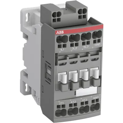
1SBL177505R1100 ABB: The AF16-22-00K-11 is a 4 pole - 690 V IEC or 600 UL contactor with Push-in Spring terminals, controlling motors up to 7.5 kW / 400 V AC (AC-3) and switching power circuits up to 30 A (AC-1) or 30 A UL general use. Thanks to the AF technology, the contactor has a wide control voltage range (24-60 V 50/60 Hz and 20-60 V DC), managing large control voltage variations, reducing panel energy consumptions and ensuring distinct operations in unstable networks. Furthermore, surge protection is built-in, offering a compact solution. AF contactors have a block type design, can be easily extended with add-on auxiliary contact blocks and an additional wide range of accessories.
Minimum Order Quantity
1 piece
Data Sheet, Technical Information
1SBC100214C0202 - Main catalog Motor protection and control Manual motor starters, contactors and overload relays (PDF) - Edition 2024
Instructions and Manuals
Operating instructions - Contactors AFC..K, contactor relays NFC..K and accessories
Instructions and Manuals (Part 2)
Contactors and Overload relays guide
CAD Dimensional Drawing
Information - 2D and 3D files for CAD systems
Product Net Width
45 mm
Product Net Depth / Length
77 mm
Product Net Height
92.3 mm
Product Net Weight
0.285 kg
Number of Main Contacts NO
2
Number of Main Contacts NC
2
Number of Auxiliary Contacts NO
0
Number of Auxiliary Contacts NC
0
Number of Poles
4P
Standards
IEC/EN 60947-1, IEC/EN 60947-4-1, UL 508, CSA C22.2 No. 60947-1-13, CSA C22.2 No. 60947-4-1
Rated Operational Voltage
Main Circuit 690 V
Rated Frequency (f)
Main Circuit 50 / 60 Hz
Conventional Free-air Thermal Current (Ith)
acc. to IEC 60947-4-1, Open Contactors Θ = 40 °C 35 A
Rated Operational Current AC-1 (Ie)
(690 V) 40 °C 30 A | (690 V) 60 °C 30 A | (690 V) 70 °C 26 A
Rated Operational Current AC-3 (Ie)
(415 V) 60 °C 18 A | (440 V) 60 °C 18 A | (500 V) 60 °C 15 A | (690 V) 60 °C 10.5 A | (380 / 400 V) 60 °C 18 A | (220 / 230 / 240 V) 60 °C 18 A
Rated Operational Power AC-3 (Pe)
(400 V) 7.5 kW | (415 V) 9 kW | (440 V) 9 kW | (500 V) 9 kW | (690 V) 9 kW | (380 / 400 V) 7.5 kW | (220 / 230 / 240 V) 4 kW
Rated Short-time Withstand Current Low Voltage (Icw)
at 40 °C Ambient Temp, in Free Air, from a Cold State 10 s 150 A | at 40 °C Ambient Temp, in Free Air, from a Cold State 15 min 35 A | at 40 °C Ambient Temp, in Free Air, from a Cold State 1 min 60 A | at 40 °C Ambient Temp, in Free Air, from a Cold State 1 s 300 A | at 40 °C Ambient Temp, in Free Air, from a Cold State 30 s 80 A
Maximum Breaking Capacity
cos phi=0.45 (cos phi=0.35 for Ie > 100 A) at 440 V 250 A | cos phi=0.45 (cos phi=0.35 for Ie > 100 A) at 690 V 106 A
Rated Insulation Voltage (Ui)
acc. to IEC 60947-4-1 and VDE 0110 (Gr. C) 690 V | acc. to UL/CSA 600 V
Maximum Electrical Switching Frequency
(AC-1) 600 cycles per hour
Maximum Mechanical Switching Frequency
3600 cycles per hour
Rated Control Circuit Voltage (Uc)
50 Hz 24 ... 60 V | 60 Hz 24 ... 60 V | DC Operation 20 ... 60 V
Power Loss
at Rated Operating Conditions AC-1 per Pole 1.43 W | at Rated Operating Conditions AC-3 per Pole 0.26 W
Operate Time
Between Coil De-energization and NC Contact Closing 13 ... 98 ms | Between Coil De-energization and NO Contact Opening 11 ... 95 ms | Between Coil Energization and NC Contact Opening 38 ... 90 ms | Between Coil Energization and NO Contact Closing 40 ... 95 ms
Mounting on DIN Rail
TH35-15 (35 x 15 mm Mounting Rail) acc. to IEC 60715 | TH35-7.5 (35 x 7.5 mm Mounting Rail) acc. to IEC 60715
Mounting by Screws (not supplied)
2 x M4 screws placed diagonally
Connecting Capacity Main Circuit
Flexible with Ferrule 1/2x 0.5 ... 4 mm² | Flexible with Insulated Ferrule 1x 0.5 ... 4 mm² | Flexible with Insulated Ferrule 2x 0.5 ... 2.5 mm² | Flexible 1/2x 0.5 ... 4 mm² | Rigid Solid 1/2x 1 ... 2.5 mm² | Rigid Stranded 1/2x 4 ... 6 mm²
Connecting Capacity Control Circuit
Flexible with Ferrule 1/2x 0.5 ... 2.5 mm² | Flexible with Insulated Ferrule 1/2x 0.5 ... 1.5 mm² | Flexible 1/2x 0.5 ... 2.5 mm² | Rigid Solid 1/2x 1 ... 2.5 mm²
Wire Stripping Length
Control Circuit 10 mm | Main Circuit 10 mm
Degree of Protection
acc. to IEC 60529, IEC 60947-1, EN 60529 Coil Terminals IP20 | acc. to IEC 60529, IEC 60947-1, EN 60529 Main Terminals IP20
Terminal Type
Push-in Spring Terminals
Product Name
Block Contactor
Maximum Operating Voltage UL/CSA
Main Circuit 600 V
General Use Rating UL/CSA
(600 V AC) 30 A
Connecting Capacity Main Circuit UL/CSA
Rigid Solid 1/2x 18-14 AWG | Rigid Stranded 1/2x 18-10 AWG
Connecting Capacity Control Circuit UL/CSA
Rigid Solid 1/2x 18-14 AWG
Ambient Air Temperature
Close to Contactor for Storage -60 ... +80 °C | Near Contactor for Operation in Free Air -40 ... 70 °C
Climatic Withstand
Category B according to IEC 60947-1 Annex Q
Maximum Operating Altitude Permissible
Without Derating 3000 m
Resistance to Shock acc. to IEC 60068-2-27
Closed, Shock Direction: B1 25 g | Open, Shock Direction: B1 5 g | Shock Direction: A 30 g | Shock Direction: B2 15 g | Shock Direction: C1 25 g | Shock Direction: C2 25 g
Resistance to Vibrations
4g Closed Position & 2g Open position 5 ... 300 Hz
Pollution Degree
3
REACH Declaration
REACH - Letter of Confirmation for block contactors, contactor relays, installation contactors, mini contactors, mini contactor relays, thermal overload relays, electronic overload relays and related accessories
RoHS Information
RoHS II declaration for block contactors, installation contactors, mini contactors, mini contactor relays, thermal overload relays, electronic overload relays and related accessories
RoHS Status
Following EU Directive 2011/65/EU and Amendment 2015/863 July 22, 2019
Toxic Substances Control Act - TSCA
Toxic Substances Control Act (TSCA) declaration for Contactors
WEEE B2C / B2B
Business To Business
WEEE Category
5. Small Equipment (No External Dimension More Than 50 cm)
End Of Life Disassembling Instructions
End of life instruction AF(S)09/12/16/26/30/38(Z)(B)(K)(RT) Contactors & NF(Z)(B)(K)(RT) Contactors relays
Environmental Product Declaration - EPD
Environmental Product Declaration - AF09/12/16(Z)(B) Contactors and NF(Z) Contactor relaysAF(S)09/12/16(Z)(B) Contactors and NF(Z)(B) Contactors Relays (FR)
Sustainable Material Content in Packaging (wt. %)
Recycled Cardboard - 86 %
Sustainable Material Content in Product (wt. %)
Recycled Metal - 28 %
CB Certificate
CB Certificate AF09, AF12, AF16, AF09(Z)B, AF12(Z)B, AF16(Z)B 3 and 4-pole contactors, AFS09, AFS12, AFS16 safety contactors
CCC Certificate
CCC Certificate AF09, AF12, AF16, AF09(Z)B, AF12(Z)B, AF16(Z)B 3 and 4-pole contactors, AFS09, AFS12, AFS16 safety contactors
Declaration of Conformity - CCC
CCC Declaration of Conformity, Contactor, AF*09, AF*12, AF*16, Made in France | CCC Declaration of Conformity, Contactor, AF09,AF12,AF16, Made in China
Declaration of Conformity - CE
EU Declaration of Conformity AF09... AF96-30-.., AF09...38(Z)-30..K 3-pole Contactors
Declaration of Conformity - UKCA
UK Declaration of Conformity AF09... AF96-30-.., AF09...38(Z)-30..K 3-pole Contactors
LR Certificate
LRS Certificate AF(S)09..(K) ... AF96 3 and 4-pole contactors and CA(L)4..(K), CAT4, CC4 auxiliary contact blocks
Package Level 1 Units
box 1 piece
Package Level 1 Width
87 mm
Package Level 1 Depth / Length
79 mm
Package Level 1 Height
47 mm
Package Level 1 Gross Weight
0.3 kg
Package Level 1 EAN
3471523018693
Object Classification Code
Q
ETIM 7
EC000066 - Power contactor, AC switching
ETIM 8
EC000066 - Power contactor, AC switching
ETIM 9
EC000066 - Power contactor, AC switching
eClass
V11.0 : 27371003
UNSPSC
39121529
Feature AF technology enables operation across a broad control voltage range, reducing misoperation and panel energy consumption. Business impact: more reliable control in networks with voltage fluctuations and lower energy waste; Application: conveyors, pumps, and fans in variable-power environments. The 4-pole design with a main circuit rated up to 690 V supports motor loads up to 7.5 kW at 400 V and higher voltages, enabling compact drives for industrial automation. Measurable outcome: simpler protection schemes and fewer misstarts in high-demand lines. Feature Push-in Spring Terminals streamline wiring, lowering installation time and torque concerns while improving conductor retention in control cabinets; Application: panel builders seeking fast, repeatable terminations. Feature Built-in surge protection guards coils and contacts, reducing EMI and extending lifecycle in unstable networks; Application: critical equipment in factories and process lines. Feature DIN rail mounting TH35-15 or TH35-7.5 and compatibility with add-on auxiliary contact blocks support scalable, modular control architectures; Application: scalable automation of OEM lines with future upgrades. Feature Compact footprint and 0.3 kg weight, plus IP20 protection, simplify installation in crowded panels; Application: space-constrained control panels and retrofit projects.
Get a Quick Quote for a ABB 1SBL177505R1100
Chat with us on WhatsApp - fast responses guaranteed
Need to speak with someone? We'll call you back within 2 hours during business hours
Interested in ABB 1SBL177505R1100?
Enquire Now
FAQs
The contactor supports DIN rail mounting on TH35-15 or TH35-7.5 rails, enabling quick installation in standard control panels. It also specifies mounting with two M4 screws diagonally if screws are used, aiding retrofit and cabinet rework projects. This flexibility helps engineers align with existing panel architectures and reduces installation time.
The coil accepts 24 to 60 V across AC and DC variants, specifically 50/60 Hz 24–60 V and DC operation from 20–60 V. This wide range supports networks with voltage variations, minimizes misoperation, and reduces the need for multiple coil variants in a single installation.
AC-1 rated current is up to 30 A at 690 V (40 °C), while AC-3 ratings include 18 A at various voltages up to 690 V (60 °C). The device can switch loads up to 7.5 kW at 400 V in AC-3, and up to 9 kW at higher voltages, balancing motor control needs with compact enclosure requirements.
Yes. The 1SBL177505R1100 complies with IEC/EN 60947-1 and 60947-4-1, UL 508, and CSA C22.2 standards, with additional DoC and regional declarations. This broad certification support ensures suitability for global deployments and reduces compliance risk in multi-site projects.
Its AF technology tolerates wide control voltage ranges, reducing nuisance trips and energy waste. The coil and surge protection extend reliability in unstable networks, while push-in terminals and DIN-rail mounting speed installation. Expandability with auxiliary contact blocks enables scalable automation, minimizing future retrofit costs and delivering faster time-to-value for motor control applications.