ABB 1SBL231001R8400 Block Contactor - IEC/UL 60947-4-1
Part Number: 1SBL231001R8400
Quick Summary
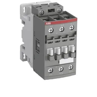
ABB 1SBL231001R8400 block contactor is a 3-pole AC switch for motor control. This device is designed to simplify control panel design by providing a reliable, compact solution that aligns with standard industrial practices. Users often struggle with coil voltage compatibility and space constraints in cabinets; 110 V AC 50/60 Hz control and a compact 45 mm width address these challenges while maintaining robust performance. The product carries CE, UL/CSA, and CB certifications and IP20 protection, ensuring compliance and field suitability. By integrating easily with AF family accessories and DIN-rail mounting, this contactor supports scalable automation projects and reduces long-term maintenance costs.
Product Information
Extended Description
1SBL231001R8400 ABB: The AFC26-30-00-84 is a 3-pole - 690 V IEC or 600 V UL contactor withScrew terminals, mainly controlling power circuits up to 11 kW / 400 V AC (AC-3) or 15 hp / 480 V AC UL and 45 A (AC-1) or 45 A UL general use. Within the AF platform, AFC contactors offer an optimized operating time for AC controlled applications with electromagnetic coil (control voltage : 110 V AC 50 Hz / 110 ... 120 V AC 60 Hz). AFC contactors have a block type design and can be easily extended with add-on auxiliary contact blocks and a wide range of additionnal accessories.
Minimum Order Quantity
1 piece
Customs Tariff Number
85364900
Data Sheet, Technical Information
1SBC100219C0201 AFC contactors for AC control applications_Catalog PDF
Instructions and Manuals
Installation instructions AF(C)09...38(Z)(B) Contactors, NF(C)(Z)(B)22...80E Contactor relays and CA4, CAL4, CAT4, CC4, LDC4 Accessories
Instructions and Manuals (Part 2)
Contactors and Overload relays guide
CAD Dimensional Drawing
Information - 2D and 3D files for CAD systems
Product Net Width
45 mm
Product Net Depth / Length
86 mm
Product Net Height
86 mm
Product Net Weight
0.357 kg
Number of Main Contacts NO
3
Number of Main Contacts NC
0
Number of Auxiliary Contacts NO
0
Number of Auxiliary Contacts NC
0
Number of Poles
3P
Standards
IEC/EN 60947-1, IEC/EN 60947-4-1, UL 60947-4-1, CSA C22.2 No. 60947-4-1, UL 60335-2-40 LZGH2 A2L
Rated Operational Voltage
Main Circuit 690 V
Rated Frequency (f)
Control Circuit 50 / 60 Hz | Main Circuit 50 / 60 Hz
Conventional Free-air Thermal Current (Ith)
acc. to IEC 60947-4-1, Open Contactors Θ = 40 °C 50 A | acc. to IEC 60947-5-1, Θ = 40 °C 16 A
Rated Operational Current AC-1 (Ie)
(690 V) 40 °C 45 A | (690 V) 60 °C 40 A | (690 V) 70 °C 32 A
Rated Operational Current AC-3 (Ie)
(415 V) 60 °C 26 A | (440 V) 60 °C 26 A | (500 V) 60 °C 23 A | (690 V) 60 °C 17 A | (380 / 400 V) 60 °C 26 A | (220 / 230 / 240 V) 60 °C 26 A
Rated Operational Current AC-3e (Ie)
(415 V) 60 °C 26 A | (440 V) 60 °C 26 A | (500 V) 60 °C 23 A | (690 V) 60 °C 17 A | (380 / 400 V) 60 °C 26 A | (220 / 230 / 240 V) 60 °C 26 A
Rated Operational Current DC-1 (Ie)
(110 V) 2 Poles in Series, 40 °C 45 A | (110 V) 2 Poles in Series, 60 °C 40 A | (110 V) 2 Poles in Series, 70 °C 32 A | (110 V) 3 Poles in Series, 40 °C 45 A | (110 V) 3 Poles in Series, 60 °C 40 A | (110 V) 3 Poles in Series, 70 °C 32 A | (220 V) 3 Poles in Series, 40 °C 45 A | (220 V) 3 Poles in Series, 60 °C 40 A | (220 V) 3 Poles in Series, 70 °C 32 A | (72 V) 1-Pole, 40 °C 45 A | (72 V) 1-Pole, 60 °C 40 A | (72 V) 1-Pole, 70 °C 32 A | (72 V) 2 Poles in Series, 40 °C 45 A | (72 V) 2 Poles in Series, 60 °C 40 A | (72 V) 2 Poles in Series, 70 °C 32 A | (72 V) 3 Poles in Series, 40 °C 45 A | (72 V) 3 Poles in Series, 60 °C 40 A | (72 V) 3 Poles in Series, 70 °C 32 A
Rated Operational Current DC-3 (Ie)
(110 V) 2 Poles in Series, 40 °C 45 A | (110 V) 2 Poles in Series, 60 °C 40 A | (110 V) 2 Poles in Series, 70 °C 32 A | (110 V) 3 Poles in Series, 40 °C 45 A | (110 V) 3 Poles in Series, 60 °C 40 A | (110 V) 3 Poles in Series, 70 °C 32 A | (220 V) 3 Poles in Series, 40 °C 45 A | (220 V) 3 Poles in Series, 60 °C 40 A | (220 V) 3 Poles in Series, 70 °C 32 A | (72 V) 1-Pole, 40 °C 45 A | (72 V) 1-Pole, 60 °C 40 A | (72 V) 1-Pole, 70 °C 32 A | (72 V) 2 Poles in Series, 40 °C 45 A | (72 V) 2 Poles in Series, 60 °C 40 A | (72 V) 2 Poles in Series, 70 °C 32 A | (72 V) 3 Poles in Series, 40 °C 45 A | (72 V) 3 Poles in Series, 60 °C 40 A | (72 V) 3 Poles in Series, 70 °C 32 A
Rated Operational Current DC-5 (Ie)
(110 V) 2 Poles in Series, 40 °C 45 A | (110 V) 2 Poles in Series, 60 °C 40 A | (110 V) 2 Poles in Series, 70 °C 32 A | (110 V) 3 Poles in Series, 40 °C 45 A | (110 V) 3 Poles in Series, 60 °C 40 A | (110 V) 3 Poles in Series, 70 °C 32 A | (220 V) 3 Poles in Series, 40 °C 20 A | (220 V) 3 Poles in Series, 60 °C 20 A | (220 V) 3 Poles in Series, 70 °C 20 A | (72 V) 1-Pole, 40 °C 20 A | (72 V) 1-Pole, 60 °C 20 A | (72 V) 1-Pole, 70 °C 20 A | (72 V) 2 Poles in Series, 40 °C 45 A | (72 V) 2 Poles in Series, 60 °C 40 A | (72 V) 2 Poles in Series, 70 °C 32 A | (72 V) 3 Poles in Series, 40 °C 45 A | (72 V) 3 Poles in Series, 60 °C 40 A | (72 V) 3 Poles in Series, 70 °C 32 A
Rated Operational Power AC-3 (Pe)
(415 V) 11 kW | (440 V) 15 kW | (500 V) 15 kW | (690 V) 15 kW | (380 / 400 V) 11 kW | (220 / 230 / 240 V) 6.5 kW
Rated Operational Power AC-3e (Pe)
(415 V) 11 kW | (440 V) 15 kW | (500 V) 15 kW | (690 V) 15 kW | (380 / 400 V) 11 kW | (220 / 230 / 240 V) 6.5 kW
Rated Operational Power AC-6b (Pe)
(400 / 415 V) 40 °C, 50 / 60 Hz 19 kvar | (400 / 415 V) 70 °C, 50 / 60 Hz 15 kvar | (400 / 415 V) 55 °C, 50 / 60 Hz 19 kvar | (500 / 550 V), 40 °C, 50 / 60 Hz 23 kvar | (500 / 550 V) 55 °C, 50 / 60 Hz 23 kvar | (500 / 550 V) 70 °C, 50 / 60 Hz 19 kvar | (690 V) 40 °C, 50 / 60 Hz 32 kvar | (690 V) 55 °C, 50 / 60 Hz 32 kvar | (690 V) 70 °C, 50 / 60 Hz 26 kvar
Rated Short-time Withstand Current Low Voltage (Icw)
at 40 °C Ambient Temp, in Free Air, from a Cold State 10 s 350 A | at 40 °C Ambient Temp, in Free Air, from a Cold State 15 min 50 A | at 40 °C Ambient Temp, in Free Air, from a Cold State 1 min 150 A | at 40 °C Ambient Temp, in Free Air, from a Cold State 1 s 700 A | at 40 °C Ambient Temp, in Free Air, from a Cold State 30 s 225 A
Maximum Breaking Capacity
cos phi=0.45 (cos phi=0.35 for Ie > 100 A) at 440 V 500 A | cos phi=0.45 (cos phi=0.35 for Ie > 100 A) at 690 V 200 A
Rated Insulation Voltage (Ui)
acc. to IEC 60947-4-1 690 V | acc. to UL/CSA 600 V
Rated Impulse Withstand Voltage (Uimp)
6 kV
Maximum Electrical Switching Frequency
(AC-1) 600 cycles per hour | (AC-15) 0 cycles per hour | (AC-2 / AC-4) 150 cycles per hour | (AC-3) 1200 cycles per hour | (DC-13) 0 cycles per hour
Maximum Mechanical Switching Frequency
3600 cycles per hour
Rated Control Circuit Voltage (Uc)
50 Hz 110 V | 60 Hz 110 ... 120 V
Coil Consumption
Average Holding Value 50 / 60 Hz 8 V·A | Average Pull-in Value 50 Hz 70 V·A | Average Pull-in Value 60 Hz 66 V·A
Power Loss
at Rated Operating Conditions AC-1 per Pole 1.8 W | at Rated Operating Conditions AC-3 per Pole 0.6 W
Operate Time
Between Coil De-energization and NC Contact Closing 9 ... 20 ms | Between Coil De-energization and NO Contact Opening 4 ... 18 ms | Between Coil Energization and NC Contact Opening 7 ... 21 ms | Between Coil Energization and NO Contact Closing 10 ... 26 ms
Mounting on DIN Rail
TH35-15 (35 x 15 mm Mounting Rail) acc. to IEC 60715 | TH35-7.5 (35 x 7.5 mm Mounting Rail) acc. to IEC 60715
Mounting by Screws (not supplied)
2 x M4 screws placed diagonally
Connecting Capacity Main Circuit
Flexible with Ferrule 1/2x 1.5 ... 10 mm² | Flexible with Insulated Ferrule 1x 1.5 ... 10 mm² | Flexible with Insulated Ferrule 2x 1.5 ... 4 mm² | Rigid Solid 1/2x 2.5 ... 4 mm² | Rigid Stranded 1/2x 2.5 ... 10 mm²
Connecting Capacity Control Circuit
Flexible with Ferrule 1/2x 0.75 ... 2.5 mm² | Flexible with Insulated Ferrule 1x 0.75 ... 2.5 mm² | Flexible with Insulated Ferrule 2x 0.75 ... 1.5 mm² | Rigid Solid 1/2x 1 ... 2.5 mm² | Rigid Stranded 1/2x 1 ... 2.5 mm²
Wire Stripping Length
Control Circuit 10 mm | Main Circuit 14 mm
Degree of Protection
acc. to IEC 60529, IEC 60947-1, EN 60529 Coil Terminals IP20 | acc. to IEC 60529, IEC 60947-1, EN 60529 Main Terminals IP20
Tightening Torque
Control Circuit 1.2 N·m | Main Circuit 2.5 N·m
Terminal Type
Screw Terminals
Product Name
Block Contactor
NEMA Size
1
Continuous Current Rating NEMA
27 A
Horsepower Rating NEMA
(115 V AC) Single Phase 2 Hp | (200 V AC) Three Phase 7-1/2 Hp | (230 V AC) Single Phase 3 Hp | (230 V AC) Three Phase 7-1/2 Hp | (460 V AC) Three Phase 10 Hp | (575 V AC) Three Phase 10 Hp
Maximum Operating Voltage UL/CSA
Main Circuit 600 V
General Use Rating UL/CSA
(600 V AC) 45 A
Horsepower Rating UL/CSA
(120 V AC) Single Phase 2 hp | (200 ... 208 V AC) Three Phase 7-1/2 hp | (220 ... 240 V AC) Three Phase 7-1/2 hp | (240 V AC) Single Phase 3 hp | (440 ... 480 V AC) Three Phase 15 hp | (550 ... 600 V AC) Three Phase 20 hp
Connecting Capacity Main Circuit UL/CSA
Rigid Solid 1/2x 14-10 AWG | Rigid Stranded 1/2x 14-8 AWG
Connecting Capacity Control Circuit UL/CSA
Rigid Solid 1/2x 18-14 AWG | Rigid Stranded 1/2x 18-14 AWG
Tightening Torque UL/CSA
Control Circuit 11 in·lb | Main Circuit 22 in·lb
Full Load Amps Motor Use
(120 V AC) Single Phase 24 A | (200 ... 208 V AC) Three Phase 25.3 A | (220 ... 240 V AC) Three Phase 22 A | (240 V AC) Single Phase 17 A | (440 ... 480 V AC) Three Phase 21 A | (550 ... 600 V AC) Three Phase 22 A
Ambient Air Temperature
Close to Contactor Fitted with Thermal O/L Relay -25 ... 60 °C | Close to Contactor without Thermal O/L Relay -40 ... 70 °C | Close to Contactor without Thermal O/L Relay (0.85 ... 1.1 Uc) -40 ... 60 °C | Close to Contactor without Thermal O/L Relay (Uc) -40 ... 70 °C | Close to Contactor for Storage -60 ... +80 °C
Climatic Withstand
Category B according to IEC 60947-1 Annex Q
Maximum Operating Altitude Permissible
Without Derating 3000 m
Resistance to Shock acc. to IEC 60068-2-27
Closed, Shock Direction: B1 25 g | Open, Shock Direction: B1 5 g | Shock Direction: A 30 g | Shock Direction: B2 15 g | Shock Direction: C1 25 g | Shock Direction: C2 25 g
Resistance to Vibrations
4g Closed Position & 2g Open position 5 ... 300 Hz
Pollution Degree
3
Conflict Minerals Reporting Template (CMRT)
CMRT - Conflict Minerals Reporting Template
REACH Declaration
REACH - Letter of Confirmation for block contactors, contactor relays, installation contactors, mini contactors, mini contactor relays, thermal overload relays, electronic overload relays and related accessories
RoHS Information
RoHS II declaration for block contactors, installation contactors, mini contactors, mini contactor relays, thermal overload relays, electronic overload relays and related accessories
RoHS Status
Following EU Directive 2011/65/EU and Amendment 2015/863 July 22, 2019
Toxic Substances Control Act - TSCA
Toxic Substances Control Act (TSCA) declaration for Contactors
WEEE B2C / B2B
Business To Business
WEEE Category
5. Small Equipment (No External Dimension More Than 50 cm)
A2L Certificate – UL
UL-US A2L LZGH2 Certificate of Compliance AFC09 ... AFC38 3-pole contactors with screw terminals - UL 60335-2-40 Household and Similar Electrical Appliances - Safety - Part 2-40: Particular Requirements for Electrical Heat Pumps, Air-Conditioners and Dehumidifiers | UL-CA A2L LZGH2 Certificate of Compliance AFC09 ... AFC38 3-pole contactors with screw terminals - CSA C22.2 No. 60335-2-40 Household and Similar Electrical Appliances - Safety - Part 2-40: Particular Requirements for Electrical Heat Pumps, Air-Conditioners and Dehumidifiers
BV Certificate
BV Certificate AF(C)09...AF(C)38 3-pole and 4-pole contactors with screw and Push-in Spring terminals
CB Certificate
CB Certificate AFC26, AFC30, AFC38 3-pole contactors
CQC Certificate
CQC Certificate, Contactor, AF*26, AF*30, AF*38, Made in France
Declaration of Conformity - CCC
CCC Declaration of Conformity, Contactor, AF26, AF30, AF38, AFS26, AFS30, AFS38 Made in France
Declaration of Conformity - CE
EU Declaration of Conformity AFC09..(K) ... AFC96 3-pole Contactors
Declaration of Conformity - UKCA
UK Declaration of Conformity AFC09..(K) ... AFC96 3-pole Contactors
DNV Certificate
DNV Certificate AFC09...96 3-pole & AFC09...80 4-pole contactors with screw, push-in terminals
RINA Certificate
Rina Certificate for AFC09...AFC96 3 pole and 4 pole contactors, NFC relays ,screw and spring terminals
UL Certificate
UL-Certificate of Compliance AFC09 ... AFC38 3-pole contactors
Package Level 1 Units
box 1 piece
Package Level 1 Width
87 mm
Package Level 1 Depth / Length
87 mm
Package Level 1 Height
47 mm
Package Level 1 Gross Weight
0.38 kg
Package Level 1 EAN
3471523014763
Package Level 3 Units
1008 piece
Object Classification Code
Q
ETIM 7
EC000066 - Power contactor, AC switching
ETIM 8
EC000066 - Power contactor, AC switching
ETIM 9
EC000066 - Power contactor, AC switching
eClass
V11.0 : 27371003
UNSPSC
39121529
IDEA Granular Category Code (IGCC)
4755 >> Contactors
Feature coil voltage compatibility and low coil consumption → Business impact: reduces control panel wiring complexity and energy usage while enabling quick integration with common 110 V control circuits. Application: control circuits in new installations or retrofit projects where AC coil drive is standard. Feature 3-pole main circuit rated up to 690 V → Business impact: supports high-voltage motor loads up to 11 kW (AC-3) and 15 kW (AC-3) at 690 V, increasing equipment versatility. Application: motor starters for conveyors, fans, and pumps in HVAC and process industries. Feature screw terminals and DIN rail mounting (TH35-15/TH35-7.5) → Business impact: fast, secure installation with minimal cabinet depth, enabling compact layouts. Application: panel builders prioritizing modularity and serviceability. Feature block-contactor design with extendable auxiliary contact blocks → Business impact: scalable control logic and easier fault isolation; Application: automation systems requiring additional interlocking or signaling contacts. Feature IP20 protection and RoHS/REACH compliance → Business impact: improved reliability in clean, indoor environments with regulatory alignment. Application: standard machine controls in compliant facilities. Feature low coil hold and pull-in power (8 V·A hold; 70/66 V·A pull-in) → Business impact: reduced standby power and thermal rise, lowering cooling requirements. Application: continuous operation for extended motor control cycles. Feature mechanical and electrical ratings for AC-1, AC-3, and DC-1/3 control contexts → Business impact: broad compatibility across motor start/stop scenarios; Application: multi-manufacturer cabinet ecosystems. Feature wide standard approvals (IEC/EN, UL, CSA, CCC, UKCA) → Business impact: simplifies procurement and reduces compliance risk; Application: global installations and cross-border sourcing.
Get a Quick Quote for a ABB 1SBL231001R8400
Chat with us on WhatsApp - fast responses guaranteed
Need to speak with someone? We'll call you back within 2 hours during business hours
Interested in ABB 1SBL231001R8400?
Enquire Now
FAQs
Install the device on a standard TH35 rail (TH35-15 or TH35-7.5). Wire the main circuit with rigid or flexible conductors per the terminal capacities, using 2 x M4 screws if mounting by screws. Tighten main circuit terminals to 2.5 N·m and control circuit terminals to 1.2 N·m. Use compatible auxiliary contact blocks for expanded control logic as needed.
The contactor features a 3-pole main circuit rated up to 690 V. Coil control voltage is 110 V AC at 50 Hz or 110–120 V AC at 60 Hz. In AC-3 service at 690 V, the rated current is 26 A (60 °C) and 17 A at higher V&Is, with AC-3e ratings matching these values. It is suitable for motor starter applications with AC-3 power switching.
The device complies with IEC/EN 60947-1 and IEC/EN 60947-4-1, and lists UL 60947-4-1, CSA C22.2 No. 60947-4-1, and other key certifications. Additional declarations cover CE, UKCA, CCC, CB, and RoHS/REACH compliance, ensuring broad regulatory acceptance across global installations.
Yes. The AFC/AFC family block contactors are designed for easy extension with add-on auxiliary contact blocks and AF accessories. This enables customized signaling, interlocking, and control logic while preserving the same mounting footprint and electrical characteristics, reducing wiring complexity during upgrades or system expansions.
Choose the 110 V coil variant for standard control circuits and ensure proper DIN-rail mounting with TH35 rails in a clean, ventilated enclosure. Maintain IP20 protection, verify tightening torques (2.5 N·m main, 1.2 N·m control), and plan for a low power loss of 0.6–1.8 W per pole depending on the load. These practices improve uptime, reduce maintenance, and deliver predictable lifecycle performance.