ABB AFC26-30-00-88 Contactor - 690V IEC/UL, 3P
Part Number: 1SBL231001R8800
Quick Summary
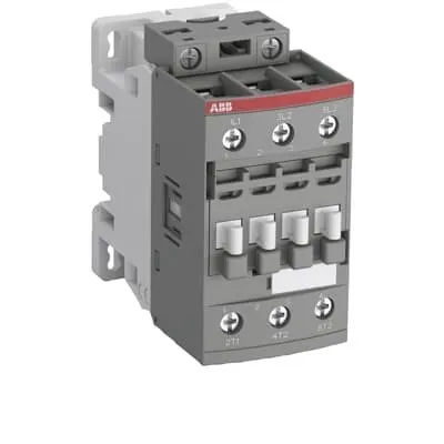
The ABB AFC26-30-00-88 Contactor is a 3-pole power switch for motor control in AC-3 circuits. In demanding panel environments, operators often face space constraints and varying coil voltages across 50 Hz and 60 Hz systems, which can lead to downtime if components aren’t compatible. This device carries IEC/EN 60947-4-1 and UL 60335-2-40 compliance, along with CE/UKCA declarations, ensuring safety and regulatory alignment. Its AF platform heritage supports easy accessory integration, including auxiliary contact blocks, for extended interlocking and monitoring. By combining compact form with robust ratings, it delivers measurable business value through reduced panel size, quicker maintenance, and predictable performance in industrial control applications.
Product Information
Extended Description
1SBL231001R8800 ABB: The AFC26-30-00-88 is a 3-pole - 690 V IEC or 600 V UL contactor withScrew terminals, mainly controlling power circuits up to 11 kW / 400 V AC (AC-3) or 15 hp / 480 V AC UL and 45 A (AC-1) or 45 A UL general use. Within the AF platform, AFC contactors offer an optimized operating time for AC controlled applications with electromagnetic coil (control voltage : 230 ... 240 V AC 50 Hz / 240 ... 260 V AC 60 Hz). AFC contactors have a block type design and can be easily extended with add-on auxiliary contact blocks and a wide range of additionnal accessories.
Lead Time
28 day
Made To Order
No
Product Sales Status
Active
Quote Only
No
Stocked At Warehouses
USSVCEXPU
Warranty Return
Product under warranty must be returned
Minimum Order Quantity
1 piece
Customs Tariff Number
85364900
Data Sheet, Technical Information
1SBC100219C0201 AFC contactors for AC control applications_Catalog PDF
Instructions and Manuals
Installation instructions AF(C)09...38(Z)(B) Contactors, NF(C)(Z)(B)22...80E Contactor relays and CA4, CAL4, CAT4, CC4, LDC4 Accessories
Instructions and Manuals (Part 2)
Contactors and Overload relays guide
CAD Dimensional Drawing
Information - 2D and 3D files for CAD systems
Product Net Width
45 mm
Product Net Depth / Length
86 mm
Product Net Height
86 mm
Product Net Weight
0.352 kg
Number of Main Contacts NO
3
Number of Main Contacts NC
0
Number of Auxiliary Contacts NO
0
Number of Auxiliary Contacts NC
0
Number of Poles
3P
Standards
IEC/EN 60947-1, IEC/EN 60947-4-1, UL 60947-4-1, CSA C22.2 No. 60947-4-1, UL 60335-2-40 LZGH2 A2L
Rated Operational Voltage
Main Circuit 690 V
Rated Frequency (f)
Control Circuit 50 / 60 Hz | Main Circuit 50 / 60 Hz
Conventional Free-air Thermal Current (Ith)
acc. to IEC 60947-4-1, Open Contactors Θ = 40 °C 50 A | acc. to IEC 60947-5-1, Θ = 40 °C 16 A
Rated Operational Current AC-1 (Ie)
(690 V) 40 °C 45 A | (690 V) 60 °C 40 A | (690 V) 70 °C 32 A
Rated Operational Current AC-3 (Ie)
(415 V) 60 °C 26 A | (440 V) 60 °C 26 A | (500 V) 60 °C 23 A | (690 V) 60 °C 17 A | (380 / 400 V) 60 °C 26 A | (220 / 230 / 240 V) 60 °C 26 A
Rated Operational Current AC-3e (Ie)
(415 V) 60 °C 26 A | (440 V) 60 °C 26 A | (500 V) 60 °C 23 A | (690 V) 60 °C 17 A | (380 / 400 V) 60 °C 26 A | (220 / 230 / 240 V) 60 °C 26 A
Rated Operational Current DC-1 (Ie)
(110 V) 2 Poles in Series, 40 °C 45 A | (110 V) 2 Poles in Series, 60 °C 40 A | (110 V) 2 Poles in Series, 70 °C 32 A | (110 V) 3 Poles in Series, 40 °C 45 A | (110 V) 3 Poles in Series, 60 °C 40 A | (110 V) 3 Poles in Series, 70 °C 32 A | (220 V) 3 Poles in Series, 40 °C 45 A | (220 V) 3 Poles in Series, 60 °C 40 A | (220 V) 3 Poles in Series, 70 °C 32 A | (72 V) 1-Pole, 40 °C 45 A | (72 V) 1-Pole, 60 °C 40 A | (72 V) 1-Pole, 70 °C 32 A | (72 V) 2 Poles in Series, 40 °C 45 A | (72 V) 2 Poles in Series, 60 °C 40 A | (72 V) 2 Poles in Series, 70 °C 32 A | (72 V) 3 Poles in Series, 40 °C 45 A | (72 V) 3 Poles in Series, 60 °C 40 A | (72 V) 3 Poles in Series, 70 °C 32 A
Rated Operational Current DC-3 (Ie)
(110 V) 2 Poles in Series, 40 °C 45 A | (110 V) 2 Poles in Series, 60 °C 40 A | (110 V) 2 Poles in Series, 70 °C 32 A | (110 V) 3 Poles in Series, 40 °C 45 A | (110 V) 3 Poles in Series, 60 °C 40 A | (110 V) 3 Poles in Series, 70 °C 32 A | (220 V) 3 Poles in Series, 40 °C 45 A | (220 V) 3 Poles in Series, 60 °C 40 A | (220 V) 3 Poles in Series, 70 °C 32 A | (72 V) 1-Pole, 40 °C 45 A | (72 V) 1-Pole, 60 °C 40 A | (72 V) 1-Pole, 70 °C 32 A | (72 V) 2 Poles in Series, 40 °C 45 A | (72 V) 2 Poles in Series, 60 °C 40 A | (72 V) 2 Poles in Series, 70 °C 32 A | (72 V) 3 Poles in Series, 40 °C 45 A | (72 V) 3 Poles in Series, 60 °C 40 A | (72 V) 3 Poles in Series, 70 °C 32 A
Rated Operational Current DC-5 (Ie)
(110 V) 2 Poles in Series, 40 °C 45 A | (110 V) 2 Poles in Series, 60 °C 40 A | (110 V) 2 Poles in Series, 70 °C 32 A | (110 V) 3 Poles in Series, 40 °C 45 A | (110 V) 3 Poles in Series, 60 °C 40 A | (110 V) 3 Poles in Series, 70 °C 32 A | (220 V) 3 Poles in Series, 40 °C 20 A | (220 V) 3 Poles in Series, 60 °C 20 A | (220 V) 3 Poles in Series, 70 °C 20 A | (72 V) 1-Pole, 40 °C 20 A | (72 V) 1-Pole, 60 °C 20 A | (72 V) 1-Pole, 70 °C 20 A | (72 V) 2 Poles in Series, 40 °C 45 A | (72 V) 2 Poles in Series, 60 °C 40 A | (72 V) 2 Poles in Series, 70 °C 32 A | (72 V) 3 Poles in Series, 40 °C 45 A | (72 V) 3 Poles in Series, 60 °C 40 A | (72 V) 3 Poles in Series, 70 °C 32 A
Rated Operational Power AC-3 (Pe)
(415 V) 11 kW | (440 V) 15 kW | (500 V) 15 kW | (690 V) 15 kW | (380 / 400 V) 11 kW | (220 / 230 / 240 V) 6.5 kW
Rated Operational Power AC-3e (Pe)
(415 V) 11 kW | (440 V) 15 kW | (500 V) 15 kW | (690 V) 15 kW | (380 / 400 V) 11 kW | (220 / 230 / 240 V) 6.5 kW
Rated Operational Power AC-6b (Pe)
(400 / 415 V) 40 °C, 50 / 60 Hz 19 kvar | (400 / 415 V) 70 °C, 50 / 60 Hz 15 kvar | (400 / 415 V) 55 °C, 50 / 60 Hz 19 kvar | (500 / 550 V), 40 °C, 50 / 60 Hz 23 kvar | (500 / 550 V) 55 °C, 50 / 60 Hz 23 kvar | (500 / 550 V) 70 °C, 50 / 60 Hz 19 kvar | (690 V) 40 °C, 50 / 60 Hz 32 kvar | (690 V) 55 °C, 50 / 60 Hz 32 kvar | (690 V) 70 °C, 50 / 60 Hz 26 kvar
Rated Short-time Withstand Current Low Voltage (Icw)
at 40 °C Ambient Temp, in Free Air, from a Cold State 10 s 350 A | at 40 °C Ambient Temp, in Free Air, from a Cold State 15 min 50 A | at 40 °C Ambient Temp, in Free Air, from a Cold State 1 min 150 A | at 40 °C Ambient Temp, in Free Air, from a Cold State 1 s 700 A | at 40 °C Ambient Temp, in Free Air, from a Cold State 30 s 225 A
Maximum Breaking Capacity
cos phi=0.45 (cos phi=0.35 for Ie > 100 A) at 440 V 500 A | cos phi=0.45 (cos phi=0.35 for Ie > 100 A) at 690 V 200 A
Rated Insulation Voltage (Ui)
acc. to IEC 60947-4-1 690 V | acc. to UL/CSA 600 V
Rated Impulse Withstand Voltage (Uimp)
6 kV
Maximum Electrical Switching Frequency
(AC-1) 600 cycles per hour | (AC-15) 0 cycles per hour | (AC-2 / AC-4) 150 cycles per hour | (AC-3) 1200 cycles per hour | (DC-13) 0 cycles per hour
Maximum Mechanical Switching Frequency
3600 cycles per hour
Rated Control Circuit Voltage (Uc)
50 Hz 230 ... 240 V | 60 Hz 240 ... 260 V
Coil Consumption
Average Holding Value 50 / 60 Hz 8 V·A | Average Pull-in Value 50 Hz 70 V·A | Average Pull-in Value 60 Hz 66 V·A
Power Loss
at Rated Operating Conditions AC-1 per Pole 1.8 W | at Rated Operating Conditions AC-3 per Pole 0.6 W
Operate Time
Between Coil De-energization and NC Contact Closing 9 ... 20 ms | Between Coil De-energization and NO Contact Opening 4 ... 18 ms | Between Coil Energization and NC Contact Opening 7 ... 21 ms | Between Coil Energization and NO Contact Closing 10 ... 26 ms
Mounting on DIN Rail
TH35-15 (35 x 15 mm Mounting Rail) acc. to IEC 60715 | TH35-7.5 (35 x 7.5 mm Mounting Rail) acc. to IEC 60715
Mounting by Screws (not supplied)
2 x M4 screws placed diagonally
Connecting Capacity Main Circuit
Flexible with Ferrule 1/2x 1.5 ... 10 mm² | Flexible with Insulated Ferrule 1x 1.5 ... 10 mm² | Flexible with Insulated Ferrule 2x 1.5 ... 4 mm² | Rigid Solid 1/2x 2.5 ... 4 mm² | Rigid Stranded 1/2x 2.5 ... 10 mm²
Connecting Capacity Control Circuit
Flexible with Ferrule 1/2x 0.75 ... 2.5 mm² | Flexible with Insulated Ferrule 1x 0.75 ... 2.5 mm² | Flexible with Insulated Ferrule 2x 0.75 ... 1.5 mm² | Rigid Solid 1/2x 1 ... 2.5 mm² | Rigid Stranded 1/2x 1 ... 2.5 mm²
Wire Stripping Length
Control Circuit 10 mm | Main Circuit 14 mm
Degree of Protection
acc. to IEC 60529, IEC 60947-1, EN 60529 Coil Terminals IP20 | acc. to IEC 60529, IEC 60947-1, EN 60529 Main Terminals IP20
Tightening Torque
Control Circuit 1.2 N·m | Main Circuit 2.5 N·m
Terminal Type
Screw Terminals
Product Name
Block Contactor
NEMA Size
1
Continuous Current Rating NEMA
27 A
Horsepower Rating NEMA
(115 V AC) Single Phase 2 Hp | (200 V AC) Three Phase 7-1/2 Hp | (230 V AC) Single Phase 3 Hp | (230 V AC) Three Phase 7-1/2 Hp | (460 V AC) Three Phase 10 Hp | (575 V AC) Three Phase 10 Hp
Maximum Operating Voltage UL/CSA
Main Circuit 600 V
General Use Rating UL/CSA
(600 V AC) 45 A
Horsepower Rating UL/CSA
(120 V AC) Single Phase 2 hp | (200 ... 208 V AC) Three Phase 7-1/2 hp | (220 ... 240 V AC) Three Phase 7-1/2 hp | (240 V AC) Single Phase 3 hp | (440 ... 480 V AC) Three Phase 15 hp | (550 ... 600 V AC) Three Phase 20 hp
Connecting Capacity Main Circuit UL/CSA
Rigid Solid 1/2x 14-10 AWG | Rigid Stranded 1/2x 14-8 AWG
Connecting Capacity Control Circuit UL/CSA
Rigid Solid 1/2x 18-14 AWG | Rigid Stranded 1/2x 18-14 AWG
Tightening Torque UL/CSA
Control Circuit 11 in·lb | Main Circuit 22 in·lb
Full Load Amps Motor Use
(120 V AC) Single Phase 24 A | (200 ... 208 V AC) Three Phase 25.3 A | (220 ... 240 V AC) Three Phase 22 A | (240 V AC) Single Phase 17 A | (440 ... 480 V AC) Three Phase 21 A | (550 ... 600 V AC) Three Phase 22 A
Ambient Air Temperature
Close to Contactor Fitted with Thermal O/L Relay -25 ... 60 °C | Close to Contactor without Thermal O/L Relay -40 ... 70 °C | Close to Contactor without Thermal O/L Relay (0.85 ... 1.1 Uc) -40 ... 60 °C | Close to Contactor without Thermal O/L Relay (Uc) -40 ... 70 °C | Close to Contactor for Storage -60 ... +80 °C
Climatic Withstand
Category B according to IEC 60947-1 Annex Q
Maximum Operating Altitude Permissible
Without Derating 3000 m
Resistance to Shock acc. to IEC 60068-2-27
Closed, Shock Direction: B1 25 g | Open, Shock Direction: B1 5 g | Shock Direction: A 30 g | Shock Direction: B2 15 g | Shock Direction: C1 25 g | Shock Direction: C2 25 g
Resistance to Vibrations
4g Closed Position & 2g Open position 5 ... 300 Hz
Pollution Degree
3
Conflict Minerals Reporting Template (CMRT)
CMRT - Conflict Minerals Reporting Template
REACH Declaration
REACH - Letter of Confirmation for block contactors, contactor relays, installation contactors, mini contactors, mini contactor relays, thermal overload relays, electronic overload relays and related accessories
RoHS Information
RoHS II declaration for block contactors, installation contactors, mini contactors, mini contactor relays, thermal overload relays, electronic overload relays and related accessories
RoHS Status
Following EU Directive 2011/65/EU and Amendment 2015/863 July 22, 2019
Toxic Substances Control Act - TSCA
Toxic Substances Control Act (TSCA) declaration for Contactors
WEEE B2C / B2B
Business To Business
WEEE Category
5. Small Equipment (No External Dimension More Than 50 cm)
A2L Certificate – UL
UL-US A2L LZGH2 Certificate of Compliance AFC09 ... AFC38 3-pole contactors with screw terminals - UL 60335-2-40 Household and Similar Electrical Appliances - Safety - Part 2-40: Particular Requirements for Electrical Heat Pumps, Air-Conditioners and Dehumidifiers | UL-CA A2L LZGH2 Certificate of Compliance AFC09 ... AFC38 3-pole contactors with screw terminals - CSA C22.2 No. 60335-2-40 Household and Similar Electrical Appliances - Safety - Part 2-40: Particular Requirements for Electrical Heat Pumps, Air-Conditioners and Dehumidifiers
BV Certificate
BV Certificate AF(C)09...AF(C)38 3-pole and 4-pole contactors with screw and Push-in Spring terminals
CB Certificate
CB Certificate AFC26, AFC30, AFC38 3-pole contactors
CQC Certificate
CQC Certificate, Contactor, AF*26, AF*30, AF*38, Made in France
Declaration of Conformity - CCC
CCC Declaration of Conformity, Contactor, AF26, AF30, AF38, AFS26, AFS30, AFS38 Made in France
Declaration of Conformity - CE
EU Declaration of Conformity AFC09..(K) ... AFC96 3-pole Contactors
Declaration of Conformity - UKCA
UK Declaration of Conformity AFC09..(K) ... AFC96 3-pole Contactors
DNV Certificate
DNV Certificate AFC09...96 3-pole & AFC09...80 4-pole contactors with screw, push-in terminals
RINA Certificate
Rina Certificate for AFC09...AFC96 3 pole and 4 pole contactors, NFC relays ,screw and spring terminals
UL Certificate
UL-Certificate of Compliance AFC09 ... AFC38 3-pole contactors
Package Level 1 Units
box 1 piece
Package Level 1 Width
87 mm
Package Level 1 Depth / Length
87 mm
Package Level 1 Height
47 mm
Package Level 1 Gross Weight
0.376 kg
Package Level 1 EAN
3471523014787
Package Level 3 Units
1008 piece
Object Classification Code
Q
ETIM 7
EC000066 - Power contactor, AC switching
ETIM 8
EC000066 - Power contactor, AC switching
ETIM 9
EC000066 - Power contactor, AC switching
eClass
V11.0 : 27371003
UNSPSC
39121529
IDEA Granular Category Code (IGCC)
4755 >> Contactors
Feature – 3-pole main circuit rated up to 690 V provides robust motor control for high-power loads. Business Impact – Enables reliable AC-3 duty for conveyors, pumps, and fans with minimum downtime. Application – Suitable for heavy workloads in manufacturing environments. Feature – Coil control voltage options of 230–240 V at 50 Hz or 240–260 V at 60 Hz ensure worldwide compatibility. Business Impact – Simplifies sourcing and stocking for global installations, lowering spare-part complexity. Application – Ideal for multi-region plants with mixed supply characteristics. Feature – Block-type design with compatibility for add-on auxiliary contact blocks. Business Impact – Extends control capabilities without replacing the main device, reducing total cost of ownership. Application – Interlocking, status signaling, and remote control scenarios. Feature – Screw terminals for main and control circuits and wide connection capacity. Business Impact – Improves wiring reliability and ease of field servicing, decreasing commissioning time. Application – Panel builders benefit from straightforward installation. Feature – DIN rail mounting on TH35-15 or TH35-7.5 permits quick, standardized installation. Business Impact – Reduces installation time and cabinet footprint, boosting efficiency. Application – OEMs integrating into standard control panels. Feature – Low power loss (AC-3 per pole 0.6 W; AC-1 per pole 1.8 W) supports energy efficiency and heat management. Business Impact – Lowers operating temperatures and cooling requirements in enclosures. Application – Continuous operation in monitored systems. Feature – IP20 protection and screw terminals ensure durable, indoor panel performance. Business Impact – Enhances reliability in workshop and factory environments with minimal ingress risk. Application – Electrical protection and circuit control in harsh environments.
Get a Quick Quote for a ABB 1SBL231001R8800
Chat with us on WhatsApp - fast responses guaranteed
Need to speak with someone? We'll call you back within 2 hours during business hours
Interested in ABB 1SBL231001R8800?
Enquire Now
FAQs
Yes. The AFC26-30-00-88 is designed for mounting on standard DIN rails TH35-15 and TH35-7.5. This enables fast, standardized installation in control panels and minimizes installation errors during panel wiring and subsequent maintenance.
For AC-3 duty at 690 V, the device provides up to 26 A rated operational current, with rated power up to 15 kW depending on the exact voltage. For AC-1, the device accommodates up to 40–45 A depending on ambient temperature. These ratings ensure suitability for typical motor and general load control in high-voltage networks.
The AFC26-30-00-88 coil is available at 230–240 V AC for 50 Hz and 240–260 V AC for 60 Hz. Coil consumption includes a holding value of 8 VA and pull-in values of 70 VA at 50 Hz or 66 VA at 60 Hz, enabling predictable energization and energy budgeting in control circuits.
This contactor complies with IEC/EN 60947-4-1, UL 60947-4-1, and CSA/C22.2 safety requirements, along with CE/UKCA declarations. It also carries IP20 protection and RoHS/REACH compliance for modern industrial installations, ensuring regulatory readiness across global facilities.
The AFC26-30-00-88 combines a compact 3P design with low coil power loss, extendable with auxiliary blocks, and standard DIN-rail mounting. These features translate to reduced panel space, lower cooling demands, faster commissioning, and easier maintenance—driving lower total cost of ownership and improved uptime in automated lines.