ABB AF26ZB-30-00-22 Block Contactor - IEC 60947-4-1
Part Number: 1SBL236061R2200
Quick Summary
ABB AF26ZB-30-00-22 Block Contactor enables reliable motor control for industrial conveyors and pumps. In real-world panels, voltage fluctuations can cause nuisance trips; this device tolerates a wide control range of 48–130 V AC/60 Hz or DC, helping maintain operation without excessive de-rating. It complies with IEC/EN 60947-1 and 60947-4-1, UL 60335-2-40, CSA listings, and other global standards, ensuring safety and interoperability. The compact block design supports easy extension with auxiliary contacts and applicable accessories, while DIN-rail mounting streamlines installation. Designed for durable, low-maintenance performance, it delivers consistent control in demanding environments and supports energy-efficient panel design for modern automation projects.
Product Information
Extended Description
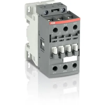
1SBL236061R2200 ABB: The AF26ZB-30-00-22 is a 3 pole - 690 V IEC or 600 UL contactor with screw terminals, controlling motors up to 11 kW / 400 V AC (AC-3) or 15 hp / 480 V UL and switching power circuits up to 45 A (AC-1) or 45 A UL general use. Thanks to the AF technology, the contactor has a wide control voltage range (48-130 V 50/60 Hz and DC), managing large control voltage variations, reducing panel energy consumptions and ensuring distinct operations in unstable networks. Furthermore, surge protection is built-in, offering a compact solution. AF contactors have a block type design, can be easily extended with add-on auxiliary contact blocks and an additional wide range of accessories.
Minimum Order Quantity
1 piece
Customs Tariff Number
85364900
Data Sheet, Technical Information
Motor control and protection for Rolling stock application_PDF
Instructions and Manuals
Installation instructions AF(C)09...38(Z)(B) Contactors, NF(C)(Z)(B)22...80E Contactor relays and CA4, CAL4, CAT4, CC4, LDC4 Accessories
Instructions and Manuals (Part 2)
Contactors and Overload relays guide
CAD Dimensional Drawing
Information - 2D and 3D files for CAD systems
Product Net Width
45 mm
Product Net Depth / Length
86 mm
Product Net Height
86 mm
Product Net Weight
0.37 kg
Number of Main Contacts NO
3
Number of Main Contacts NC
0
Number of Auxiliary Contacts NO
0
Number of Auxiliary Contacts NC
0
Number of Poles
3P
Standards
IEC/EN 60947-1, IEC/EN 60947-4-1, UL 60335-2-40 LZGH2 A2L, UL 60947-4-1, CSA C22.2 No. 60335-2-40 LZGH2 A2L, CSA C22.2 No. 60947-4-1, IEC 60077-1 (applicable parts), IEC 60077-2 (applicable parts), EN 50155 (applicable parts), TR CU 001/2011, IEC 61373, For compliance confirmation on applicable parts based on your application and combination, please consult your ABB sales representatives.
Rated Operational Voltage
Main Circuit 690 V
Rated Frequency (f)
Control Circuit 50 / 60 Hz | Main Circuit 50 / 60 Hz
Conventional Free-air Thermal Current (Ith)
acc. to IEC 60947-4-1, Open Contactors Θ = 40 °C 50 A
Rated Operational Current AC-1 (Ie)
(690 V) 40 °C 45 A | (690 V) 60 °C 40 A | (690 V) 70 °C 32 A
Rated Operational Current AC-3 (Ie)
(415 V) 60 °C 26 A | (440 V) 60 °C 26 A | (500 V) 60 °C 23 A | (690 V) 60 °C 17 A | (380 / 400 V) 60 °C 26 A | (220 / 230 / 240 V) 60 °C 26 A
Rated Operational Current AC-3e (Ie)
(415 V) 60 °C 26 A | (440 V) 60 °C 26 A | (500 V) 60 °C 23 A | (690 V) 60 °C 17 A | (380 / 400 V) 60 °C 26 A | (220 / 230 / 240 V) 60 °C 26 A
Rated Operational Current DC-1 (Ie)
(110 V) 2 Poles in Series, 40 °C 45 A | (110 V) 2 Poles in Series, 60 °C 40 A | (110 V) 2 Poles in Series, 70 °C 32 A | (110 V) 3 Poles in Series, 40 °C 45 A | (110 V) 3 Poles in Series, 60 °C 40 A | (110 V) 3 Poles in Series, 70 °C 32 A | (220 V) 3 Poles in Series, 40 °C 45 A | (220 V) 3 Poles in Series, 60 °C 40 A | (220 V) 3 Poles in Series, 70 °C 32 A | (72 V) 1-Pole, 40 °C 45 A | (72 V) 1-Pole, 60 °C 40 A | (72 V) 1-Pole, 70 °C 32 A | (72 V) 2 Poles in Series, 40 °C 45 A | (72 V) 2 Poles in Series, 60 °C 40 A | (72 V) 2 Poles in Series, 70 °C 32 A | (72 V) 3 Poles in Series, 40 °C 45 A | (72 V) 3 Poles in Series, 60 °C 40 A | (72 V) 3 Poles in Series, 70 °C 32 A
Rated Operational Current DC-3 (Ie)
(110 V) 2 Poles in Series, 40 °C 45 A | (110 V) 2 Poles in Series, 60 °C 40 A | (110 V) 2 Poles in Series, 70 °C 32 A | (110 V) 3 Poles in Series, 40 °C 45 A | (110 V) 3 Poles in Series, 60 °C 40 A | (110 V) 3 Poles in Series, 70 °C 32 A | (220 V) 3 Poles in Series, 40 °C 45 A | (220 V) 3 Poles in Series, 60 °C 40 A | (220 V) 3 Poles in Series, 70 °C 32 A | (72 V) 1-Pole, 40 °C 45 A | (72 V) 1-Pole, 60 °C 40 A | (72 V) 1-Pole, 70 °C 32 A | (72 V) 2 Poles in Series, 40 °C 45 A | (72 V) 2 Poles in Series, 60 °C 40 A | (72 V) 2 Poles in Series, 70 °C 32 A | (72 V) 3 Poles in Series, 40 °C 45 A | (72 V) 3 Poles in Series, 60 °C 40 A | (72 V) 3 Poles in Series, 70 °C 32 A
Rated Operational Current DC-5 (Ie)
(110 V) 2 Poles in Series, 40 °C 45 A | (110 V) 2 Poles in Series, 60 °C 40 A | (110 V) 2 Poles in Series, 70 °C 32 A | (110 V) 3 Poles in Series, 40 °C 45 A | (110 V) 3 Poles in Series, 60 °C 40 A | (110 V) 3 Poles in Series, 70 °C 32 A | (220 V) 3 Poles in Series, 40 °C 20 A | (220 V) 3 Poles in Series, 60 °C 20 A | (220 V) 3 Poles in Series, 70 °C 20 A | (72 V) 1-Pole, 40 °C 20 A | (72 V) 1-Pole, 60 °C 20 A | (72 V) 1-Pole, 70 °C 20 A | (72 V) 2 Poles in Series, 40 °C 45 A | (72 V) 2 Poles in Series, 60 °C 40 A | (72 V) 2 Poles in Series, 70 °C 32 A | (72 V) 3 Poles in Series, 40 °C 45 A | (72 V) 3 Poles in Series, 60 °C 40 A | (72 V) 3 Poles in Series, 70 °C 32 A
Rated Operational Power AC-3 (Pe)
(415 V) 11 kW | (440 V) 15 kW | (500 V) 15 kW | (690 V) 15 kW | (380 / 400 V) 11 kW | (220 / 230 / 240 V) 6.5 kW
Rated Operational Power AC-3e (Pe)
(415 V) 11 kW | (440 V) 15 kW | (500 V) 15 kW | (690 V) 15 kW | (380 / 400 V) 11 kW | (220 / 230 / 240 V) 6.5 kW
Rated Short-time Withstand Current Low Voltage (Icw)
at 40 °C Ambient Temp, in Free Air, from a Cold State 10 s 350 A | at 40 °C Ambient Temp, in Free Air, from a Cold State 15 min 50 A | at 40 °C Ambient Temp, in Free Air, from a Cold State 1 min 150 A | at 40 °C Ambient Temp, in Free Air, from a Cold State 1 s 700 A | at 40 °C Ambient Temp, in Free Air, from a Cold State 30 s 225 A
Maximum Breaking Capacity
cos phi=0.45 (cos phi=0.35 for Ie > 100 A) at 440 V 500 A | cos phi=0.45 (cos phi=0.35 for Ie > 100 A) at 690 V 200 A
Rated Insulation Voltage (Ui)
acc. to IEC 60947-4-1 690 V | acc. to UL/CSA 600 V
Rated Impulse Withstand Voltage (Uimp)
6 kV
Maximum Electrical Switching Frequency
(AC-1) 600 cycles per hour | (AC-2 / AC-4) 150 cycles per hour | (AC-3) 1200 cycles per hour
Maximum Mechanical Switching Frequency
3600 cycles per hour
Rated Control Circuit Voltage (Uc)
50 Hz 48 ... 130 V | 60 Hz 48 ... 130 V | DC Operation 48 ... 130 V
Power Loss
at Rated Operating Conditions AC-1 per Pole 1.8 W | at Rated Operating Conditions AC-3 per Pole 0.6 W
Operate Time
Between Coil De-energization and NC Contact Closing 13 ... 98 ms | Between Coil De-energization and NO Contact Opening 11 ... 95 ms | Between Coil Energization and NC Contact Opening 38 ... 90 ms | Between Coil Energization and NO Contact Closing 40 ... 95 ms
Mounting on DIN Rail
TH35-15 (35 x 15 mm Mounting Rail) acc. to IEC 60715 | TH35-7.5 (35 x 7.5 mm Mounting Rail) acc. to IEC 60715
Mounting by Screws (not supplied)
2 x M4 screws placed diagonally
Connecting Capacity Main Circuit
Flexible with Ferrule 1/2x 1.5 ... 10 mm² | Flexible with Insulated Ferrule 1x 1.5 ... 10 mm² | Flexible with Insulated Ferrule 2x 1.5 ... 4 mm² | Rigid Solid 1/2x 2.5 ... 4 mm² | Rigid Stranded 1/2x 2.5 ... 10 mm²
Connecting Capacity Control Circuit
Flexible with Ferrule 1/2x 0.75 ... 2.5 mm² | Flexible with Insulated Ferrule 1x 0.75 ... 2.5 mm² | Flexible with Insulated Ferrule 2x 0.75 ... 1.5 mm² | Rigid Solid 1/2x 1 ... 2.5 mm² | Rigid Stranded 1/2x 1 ... 2.5 mm²
Wire Stripping Length
Control Circuit 10 mm | Main Circuit 14 mm
Degree of Protection
acc. to IEC 60529, IEC 60947-1, EN 60529 Coil Terminals IP20 | acc. to IEC 60529, IEC 60947-1, EN 60529 Main Terminals IP20
Tightening Torque
Control Circuit 1.2 N·m | Main Circuit 2.5 N·m
Terminal Type
Screw Terminals
Product Name
Block Contactor
NEMA Size
1
Continuous Current Rating NEMA
27 A
Horsepower Rating NEMA
(115 V AC) Single Phase 2 Hp | (200 V AC) Three Phase 7-1/2 Hp | (230 V AC) Single Phase 3 Hp | (230 V AC) Three Phase 7-1/2 Hp | (460 V AC) Three Phase 10 Hp | (575 V AC) Three Phase 10 Hp
Maximum Operating Voltage UL/CSA
Main Circuit 600 V
General Use Rating UL/CSA
(600 V AC) 45 A
Horsepower Rating UL/CSA
(120 V AC) Single Phase 2 hp | (200 ... 208 V AC) Three Phase 7-1/2 hp | (220 ... 240 V AC) Three Phase 7-1/2 hp | (240 V AC) Single Phase 3 hp | (440 ... 480 V AC) Three Phase 15 hp | (550 ... 600 V AC) Three Phase 20 hp
Connecting Capacity Main Circuit UL/CSA
Rigid Solid 1/2x 14-10 AWG | Rigid Stranded 1/2x 14-8 AWG
Connecting Capacity Control Circuit UL/CSA
Rigid Solid 1/2x 18-14 AWG | Rigid Stranded 1/2x 18-14 AWG
Tightening Torque UL/CSA
Control Circuit 11 in·lb | Main Circuit 22 in·lb
Full Load Amps Motor Use
(120 V AC) Single Phase 24 A | (200 ... 208 V AC) Three Phase 25.3 A | (220 ... 240 V AC) Three Phase 22 A | (240 V AC) Single Phase 17 A | (440 ... 480 V AC) Three Phase 21 A | (550 ... 600 V AC) Three Phase 22 A
Ambient Air Temperature
Close to Contactor Fitted with Thermal O/L Relay -25 ... 60 °C | Close to Contactor without Thermal O/L Relay -40 ... 70 °C | Close to Contactor for Storage -60 ... +80 °C
Climatic Withstand
Category B according to IEC 60947-1 Annex Q
Maximum Operating Altitude Permissible
Without Derating 3000 m
Shock and Vibration Withstand acc. to IEC 61373
Category 1, Class B
Pollution Degree
3
Conflict Minerals Reporting Template (CMRT)
CMRT - Conflict Minerals Reporting Template
REACH Declaration
REACH - Letter of Confirmation for block contactors, contactor relays, installation contactors, mini contactors, mini contactor relays, thermal overload relays, electronic overload relays and related accessories
RoHS Information
RoHS II declaration for block contactors, installation contactors, mini contactors, mini contactor relays, thermal overload relays, electronic overload relays and related accessories
RoHS Status
Following EU Directive 2011/65/EU and Amendment 2015/863 July 22, 2019
SCIP
d70f8eae-81f1-4adf-8ee9-d05bdf5daf0d China (CN)
Simplified SCIP
d4c6f01d-c8db-4d55-9780-c9968dbf3a7f Finland (FI) | c7974796-f5fc-4fd3-a51b-77e8c026f9ee Belgium (BE) | 25d3bdbd-ed98-4d17-89ba-493dfd40decb Norway (NO) | daf2490c-f761-4c29-81cd-7eb9dbdef3c8 Poland (PL) | 112df531-6155-4c91-a8f7-c26944b9b408 Sweden (SE) | f825d4e1-305d-4fed-97e6-6e291691b529 Portugal (PT) | d32978e3-d492-4b2b-b884-be7e3bdf00a5 Bulgaria (BG) | cca3a15d-f7c9-4762-85d1-27a049c82355 France (FR) | f76f0099-0df5-4ac3-981a-4e50065db74e Hungary (HU) | c79f4915-a712-4f83-b9c6-a4e3e8eb7040 Germany (DE) | 877abd8d-cc42-4e62-bddc-18ac8c469c78 France (FR) | e2873c25-cbc6-4aed-b355-9b719cd0cd77 Netherlands (NL) | 0f02227f-1802-4bd3-ba4f-ee2108b236e8 Sweden (SE) | 04b6223d-7dac-4c16-a9da-780c0b5a6808 Germany (DE) | 50e9f47e-8720-4316-83de-d9afa4acf586 Belgium (BE) | 6b1280b1-b0e9-4188-9a56-c6a945a874e3 Spain (ES) | 183b315c-d5e0-4e26-a76f-a14523c4572a Germany (DE) | de15a7e1-a15e-4ee7-8df5-ac4eb6e29a91 Czech Republic (CZ) | 03371e32-d408-4372-aed0-61dc56b40645 Poland (PL) | b2a2ba73-056f-42fe-8194-2366c62d5dd8 Germany (DE) | 1a41321f-2e42-4ff8-9719-10c320cda45a Denmark (DK) | ccdb5ea3-22eb-49ee-b664-7ca571edbd34 Germany (DE) | 59b6bb47-14a8-4bb8-afc1-7918a4b9a61e Croatia (HR) | 3bcc44d9-eaab-415c-add4-10e47975ab97 Hungary (HU) | e2d397e2-88fa-4a4f-a830-1345780c410c Poland (PL) | 4a1a253f-a788-4a9b-9a74-63a800dacff3 Greece (GR) | a5083e1a-cab5-4197-916c-1d006319d91b Estonia (EE)
Toxic Substances Control Act - TSCA
Toxic Substances Control Act (TSCA) declaration for Contactors
WEEE B2C / B2B
Business To Business
WEEE Category
5. Small Equipment (No External Dimension More Than 50 cm)
End Of Life Disassembling Instructions
End of life instruction AF(S)09/12/16/26/30/38(Z)(B)(K)(RT) Contactors & NF(Z)(B)(K)(RT) Contactors relays
Environmental Product Declaration - EPD
Environmental Product Declaration AF(S)26/30/38(Z)(B) Contactors (FR) | Environmental Product Declaration AF26/30/38(Z)(B) Contactors (CN)
Sustainable Material Content in Packaging (wt. %)
Recycled Cardboard - 86 %
Sustainable Material Content in Product (wt. %)
Recycled Metal - 28 %
A2L Certificate – UL
UL-US A2L LZGH2 Certificate of Compliance AF09 ... AF38 3-pole contactors with screw terminals - UL 60335-2-40 Household and Similar Electrical Appliances - Safety - Part 2-40: Particular Requirements for Electrical Heat Pumps, Air-Conditioners and Dehumidifiers | UL-CA A2L LZGH2 Certificate of Compliance AF09 ... AF38 3-pole contactors with screw terminals - CSA C22.2 No. 60335-2-40 Household and Similar Electrical Appliances - Safety - Part 2-40: Particular Requirements for Electrical Heat Pumps, Air-Conditioners and Dehumidifiers
CB Certificate
CB Certificate AF26(Z)(B), AF30(Z)(B), AF(Z)(B)38 3-pole contactors, AFS26, AFS30, AFS38 safety contactors
CCC Certificate
CCC Certificate AF26, AF30, AF38, AF26(Z)B, AF30(Z)B, AF38(Z)B 3 and 4-pole contactors, AFS26, AFS30, AFS38 safety contactors
CQC Certificate
CQC Certificate, Contactor, AF*26, AF*30, AF*38, Made in France
Declaration of Conformity - CCC
CCC Declaration of Conformity, Contactor, AF26, AF30, AF38, AFS26, AFS30, AFS38 Made in France
Declaration of Conformity - CE
EU Declaration of Conformity AF09 ... AF38(Z)B..(K), AF40B ... AF96B 3 and 4-pole contactors
Declaration of Conformity - UKCA
UK Declaration of Conformity AF09 ... AF38(Z)B..(K), AF40B ... AF96B 3 and 4-pole contactors
GOST Certificate
GOST_POCCFR.ME77.B07175.pdf
KC Certificate
KC Certificate AF26...AF38 3-pole contactors
UL Certificate
UL-US Certificate of Compliance AF(C)(S)09(R/M/N)-..(L)(S)(K)...AF(C)(S)38(R/M/N)..(K) 3-pole contactors screw, spring and push-in spring terminals; LDC4 additional coil terminal block; LF16-4, LG16-4, LF38-4 and LH38-4 connecting strips, LD38-4 additional terminal block | UL-CA Certificate of Compliance AF(C)(S)09(R/M/N)-..(L)(S)(K)...AF(C)(S)38(R/M/N)..(K) 3-pole contactors screw, spring and push-in spring terminals; LDC4 additional coil terminal block; LF16-4, LG16-4, LF38-4 and LH38-4 connecting strips, LD38-4 additional terminal block
UL Listing Card
E312527
Package Level 1 Units
box 1 piece
Package Level 1 Width
87 mm
Package Level 1 Depth / Length
87 mm
Package Level 1 Height
47 mm
Package Level 1 Gross Weight
0.37 kg
Package Level 1 EAN
3471523124127
Package Level 2 Units
box 21 piece
Package Level 2 Width
250 mm
Package Level 2 Depth / Length
300 mm
Package Level 2 Height
315 mm
Package Level 2 Gross Weight
16.65 kg
Package Level 3 Units
1080 piece
Object Classification Code
Q
ETIM 7
EC000066 - Power contactor, AC switching
ETIM 8
EC000066 - Power contactor, AC switching
ETIM 9
EC000066 - Power contactor, AC switching
eClass
V11.0 : 27371003
UNSPSC
39121529
IDEA Granular Category Code (IGCC)
4758 >> Iec Contactors
Feature → Business Impact → Application The AF26ZB-30-00-22 uses AF technology to tolerate large control voltage variations, reducing false switching and energy waste in unstable networks, enabling robust motor control in conveyors and pumps. This translates to improved line uptime and lower maintenance costs in manufacturing lines that experience voltage sag or surge events. Feature → Application: 3-pole main circuit rated up to 690 V with AC-3 power switching up to 26 A at 415/440/500 V and 17 A at 690 V, supporting motors up to 11 kW (400 V AC, AC-3) and 15 kW at higher voltages, ideal for drives and pumps in packaging and process lines. Feature → Business Impact → Application: Screw terminals and flexible connection options (1/2 x 1.5–10 mm²) provide reliable wiring habitability and speed during panel assembly, reducing installation time and field wiring errors in control cabinets. Feature → Application: Built-in surge protection protects coil and control circuits, increasing device longevity and reducing unplanned downtime in critical automation loops such as feeders and material handling. Feature → Business Impact → Application: Block contactor design supports add-on auxiliary contact blocks and accessories, enabling expanded control schemes without replacing the base device, ideal for expanding interlocks and signaling in evolving line configurations. Feature → Application: DIN rail mounting (TH35-15 or TH35-7.5) and optional screw mounting provide flexible installation in standard control panels, saving space and enabling retrofits in existing cabinets. Feature → Business Impact → Application: Compliance with RoHS, REACH, and global safety certificates simplifies procurement across multiple regions, reducing however complex supplier management and accelerating time to production. The combination of compact footprint, clear terminalization, and scalable accessory ecosystem supports lean automation deployments and cost-efficient maintenance.
Get a Quick Quote for a ABB 1SBL236061R2200
Chat with us on WhatsApp - fast responses guaranteed
Need to speak with someone? We'll call you back within 2 hours during business hours
Interested in ABB 1SBL236061R2200?
Enquire Now
FAQs
The unit uses Screw Terminals for the main circuit with flexible ferrule connections 1/2x 2.5–10 mm² and flexible ferrule options 1x 1.5–10 mm², plus rigid solid 1/2x 2.5–4 mm² and rigid stranded 1/2x 2.5–10 mm². This supports reliable field wiring and straightforward panel integration.
For AC-3 at 690 V, the rated operational current is 17 A at 60 °C and 23 A at 500 V variants in similar configurations. At 415 V, 60 °C the value is 26 A. These figures show suitability for motors up to about 15 kW depending on voltage and conditions.
Yes. The product complies with IEC/EN 60947-1 and 60947-4-1, UL 60335-2-40, and CSA listings, among other certifications. This ensures global applicability and simplifies cross-border procurement for multinational manufacturing operations.
Yes. The AF system uses a block design that is easily extended with add-on auxiliary contact blocks and a broad range of accessories, enabling enhanced signaling, interlocking, and control logic without replacing the base device.
Mounting is available on DIN rail TH35-15 or TH35-7.5, with optional screw mounting (2 x M4). The device is rated IP20 for coil and main terminals, suitable for typical panel environments and easy integration into standard control cabinets.