ABB 1SBL237061R1400 Contactor - 690V IEC/UL LZGH2 A2L
Part Number: 1SBL237061R1400
Quick Summary
ABB 1SBL237061R1400 Contactor is a 3-pole motor control device for demanding industrial applications. When control voltages vary, AF technology maintains reliable operation and minimizes energy waste in panels. This device meets IEC/EN 60947-4-1 and UL 60335-2-40 standards and offers IP20 protection for terminals, with CE and UL/CSA declarations supporting global deployment. The design supports extension with auxiliary contact blocks and a wide range of accessories, enabling scalable control solutions. In practice, technicians appreciate its compact footprint and DIN-rail mounting options that simplify installation in crowded control panels. For procurement teams, the combination of robust performance, standardized certification, and long service life translates into lower lifecycle costs and fewer field failures.
Product Information
Extended Description
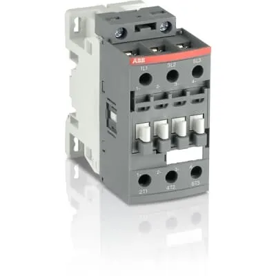
1SBL237061R1400 ABB: The AF26B-30-00-14 is a 3 pole - 690 V IEC or 600 UL contactor with screw terminals, controlling motors up to 11 kW / 400 V AC (AC-3) or 15 hp / 480 V UL and switching power circuits up to 45 A (AC-1) or 45 A UL general use. Thanks to the AF technology, the contactor has a wide control voltage range (250-500 V 50/60 Hz and DC), managing large control voltage variations, reducing panel energy consumptions and ensuring distinct operations in unstable networks. Furthermore, surge protection is built-in, offering a compact solution. AF contactors have a block type design, can be easily extended with add-on auxiliary contact blocks and an additional wide range of accessories.
Minimum Order Quantity
1 piece
Customs Tariff Number
85364900
Data Sheet, Technical Information
Motor control and protection for Rolling stock application_PDF
Instructions and Manuals
Installation instructions AF(C)09...38(Z)(B) Contactors, NF(C)(Z)(B)22...80E Contactor relays and CA4, CAL4, CAT4, CC4, LDC4 Accessories
Instructions and Manuals (Part 2)
Contactors and Overload relays guide
CAD Dimensional Drawing
Information - 2D and 3D files for CAD systems
Product Net Width
45 mm
Product Net Depth / Length
86 mm
Product Net Height
86 mm
Product Net Weight
0.37 kg
Number of Main Contacts NO
3
Number of Main Contacts NC
0
Number of Auxiliary Contacts NO
0
Number of Auxiliary Contacts NC
0
Number of Poles
3P
Standards
IEC/EN 60947-1, IEC/EN 60947-4-1, UL 60335-2-40 LZGH2 A2L, UL 60947-4-1, CSA C22.2 No. 60335-2-40 LZGH2 A2L, CSA C22.2 No. 60947-4-1, IEC 60077-1 (applicable parts), IEC 60077-2 (applicable parts), EN 50155 (applicable parts), TR CU 001/2011, IEC 61373, For compliance confirmation on applicable parts based on your application and combination, please consult your ABB sales representatives.
Rated Operational Voltage
Main Circuit 690 V
Rated Frequency (f)
Control Circuit 50 / 60 Hz | Main Circuit 50 / 60 Hz
Conventional Free-air Thermal Current (Ith)
acc. to IEC 60947-4-1, Open Contactors Θ = 40 °C 50 A
Rated Operational Current AC-1 (Ie)
(690 V) 40 °C 45 A | (690 V) 60 °C 40 A | (690 V) 70 °C 32 A
Rated Operational Current AC-3 (Ie)
(415 V) 60 °C 26 A | (440 V) 60 °C 26 A | (500 V) 60 °C 23 A | (690 V) 60 °C 17 A | (380 / 400 V) 60 °C 26 A | (220 / 230 / 240 V) 60 °C 26 A
Rated Operational Current AC-3e (Ie)
(415 V) 60 °C 26 A | (440 V) 60 °C 26 A | (500 V) 60 °C 23 A | (690 V) 60 °C 17 A | (380 / 400 V) 60 °C 26 A | (220 / 230 / 240 V) 60 °C 26 A
Rated Operational Current DC-1 (Ie)
(110 V) 2 Poles in Series, 40 °C 45 A | (110 V) 2 Poles in Series, 60 °C 40 A | (110 V) 2 Poles in Series, 70 °C 32 A | (110 V) 3 Poles in Series, 40 °C 45 A | (110 V) 3 Poles in Series, 60 °C 40 A | (110 V) 3 Poles in Series, 70 °C 32 A | (220 V) 3 Poles in Series, 40 °C 45 A | (220 V) 3 Poles in Series, 60 °C 40 A | (220 V) 3 Poles in Series, 70 °C 32 A | (72 V) 1-Pole, 40 °C 45 A | (72 V) 1-Pole, 60 °C 40 A | (72 V) 1-Pole, 70 °C 32 A | (72 V) 2 Poles in Series, 40 °C 45 A | (72 V) 2 Poles in Series, 60 °C 40 A | (72 V) 2 Poles in Series, 70 °C 32 A | (72 V) 3 Poles in Series, 40 °C 45 A | (72 V) 3 Poles in Series, 60 °C 40 A | (72 V) 3 Poles in Series, 70 °C 32 A
Rated Operational Current DC-3 (Ie)
(110 V) 2 Poles in Series, 40 °C 45 A | (110 V) 2 Poles in Series, 60 °C 40 A | (110 V) 2 Poles in Series, 70 °C 32 A | (110 V) 3 Poles in Series, 40 °C 45 A | (110 V) 3 Poles in Series, 60 °C 40 A | (110 V) 3 Poles in Series, 70 °C 32 A | (220 V) 3 Poles in Series, 40 °C 45 A | (220 V) 3 Poles in Series, 60 °C 40 A | (220 V) 3 Poles in Series, 70 °C 32 A | (72 V) 1-Pole, 40 °C 45 A | (72 V) 1-Pole, 60 °C 40 A | (72 V) 1-Pole, 70 °C 32 A | (72 V) 2 Poles in Series, 40 °C 45 A | (72 V) 2 Poles in Series, 60 °C 40 A | (72 V) 2 Poles in Series, 70 °C 32 A | (72 V) 3 Poles in Series, 40 °C 45 A | (72 V) 3 Poles in Series, 60 °C 40 A | (72 V) 3 Poles in Series, 70 °C 32 A
Rated Operational Current DC-5 (Ie)
(110 V) 2 Poles in Series, 40 °C 45 A | (110 V) 2 Poles in Series, 60 °C 40 A | (110 V) 2 Poles in Series, 70 °C 32 A | (110 V) 3 Poles in Series, 40 °C 45 A | (110 V) 3 Poles in Series, 60 °C 40 A | (110 V) 3 Poles in Series, 70 °C 32 A | (220 V) 3 Poles in Series, 40 °C 20 A | (220 V) 3 Poles in Series, 60 °C 20 A | (220 V) 3 Poles in Series, 70 °C 20 A | (72 V) 1-Pole, 40 °C 20 A | (72 V) 1-Pole, 60 °C 20 A | (72 V) 1-Pole, 70 °C 20 A | (72 V) 2 Poles in Series, 40 °C 45 A | (72 V) 2 Poles in Series, 60 °C 40 A | (72 V) 2 Poles in Series, 70 °C 32 A | (72 V) 3 Poles in Series, 40 °C 45 A | (72 V) 3 Poles in Series, 60 °C 40 A | (72 V) 3 Poles in Series, 70 °C 32 A
Rated Operational Power AC-3 (Pe)
(415 V) 11 kW | (440 V) 15 kW | (500 V) 15 kW | (690 V) 15 kW | (380 / 400 V) 11 kW | (220 / 230 / 240 V) 6.5 kW
Rated Operational Power AC-3e (Pe)
(415 V) 11 kW | (440 V) 15 kW | (500 V) 15 kW | (690 V) 15 kW | (380 / 400 V) 11 kW | (220 / 230 / 240 V) 6.5 kW
Rated Short-time Withstand Current Low Voltage (Icw)
at 40 °C Ambient Temp, in Free Air, from a Cold State 10 s 350 A | at 40 °C Ambient Temp, in Free Air, from a Cold State 15 min 50 A | at 40 °C Ambient Temp, in Free Air, from a Cold State 1 min 150 A | at 40 °C Ambient Temp, in Free Air, from a Cold State 1 s 700 A | at 40 °C Ambient Temp, in Free Air, from a Cold State 30 s 225 A
Maximum Breaking Capacity
cos phi=0.45 (cos phi=0.35 for Ie > 100 A) at 440 V 500 A | cos phi=0.45 (cos phi=0.35 for Ie > 100 A) at 690 V 200 A
Rated Insulation Voltage (Ui)
acc. to IEC 60947-4-1 690 V | acc. to UL/CSA 600 V
Rated Impulse Withstand Voltage (Uimp)
6 kV
Maximum Electrical Switching Frequency
(AC-1) 600 cycles per hour | (AC-2 / AC-4) 150 cycles per hour | (AC-3) 1200 cycles per hour
Maximum Mechanical Switching Frequency
3600 cycles per hour
Rated Control Circuit Voltage (Uc)
50 Hz 250 ... 500 V | 60 Hz 250 ... 500 V | DC Operation 250 ... 500 V
Power Loss
at Rated Operating Conditions AC-1 per Pole 1.8 W | at Rated Operating Conditions AC-3 per Pole 0.6 W
Operate Time
Between Coil De-energization and NC Contact Closing 13 ... 98 ms | Between Coil De-energization and NO Contact Opening 11 ... 95 ms | Between Coil Energization and NC Contact Opening 38 ... 90 ms | Between Coil Energization and NO Contact Closing 40 ... 95 ms
Mounting on DIN Rail
TH35-15 (35 x 15 mm Mounting Rail) acc. to IEC 60715 | TH35-7.5 (35 x 7.5 mm Mounting Rail) acc. to IEC 60715
Mounting by Screws (not supplied)
2 x M4 screws placed diagonally
Connecting Capacity Main Circuit
Flexible with Ferrule 1/2x 1.5 ... 10 mm² | Flexible with Insulated Ferrule 1x 1.5 ... 10 mm² | Flexible with Insulated Ferrule 2x 1.5 ... 4 mm² | Rigid Solid 1/2x 2.5 ... 4 mm² | Rigid Stranded 1/2x 2.5 ... 10 mm²
Connecting Capacity Control Circuit
Flexible with Ferrule 1/2x 0.75 ... 2.5 mm² | Flexible with Insulated Ferrule 1x 0.75 ... 2.5 mm² | Flexible with Insulated Ferrule 2x 0.75 ... 1.5 mm² | Rigid Solid 1/2x 1 ... 2.5 mm² | Rigid Stranded 1/2x 1 ... 2.5 mm²
Wire Stripping Length
Control Circuit 10 mm | Main Circuit 14 mm
Degree of Protection
acc. to IEC 60529, IEC 60947-1, EN 60529 Coil Terminals IP20 | acc. to IEC 60529, IEC 60947-1, EN 60529 Main Terminals IP20
Tightening Torque
Control Circuit 1.2 N·m | Main Circuit 2.5 N·m
Terminal Type
Screw Terminals
Product Name
Block Contactor
NEMA Size
1
Continuous Current Rating NEMA
27 A
Horsepower Rating NEMA
(115 V AC) Single Phase 2 Hp | (200 V AC) Three Phase 7-1/2 Hp | (230 V AC) Single Phase 3 Hp | (230 V AC) Three Phase 7-1/2 Hp | (460 V AC) Three Phase 10 Hp | (575 V AC) Three Phase 10 Hp
Maximum Operating Voltage UL/CSA
Main Circuit 600 V
General Use Rating UL/CSA
(600 V AC) 45 A
Horsepower Rating UL/CSA
(120 V AC) Single Phase 2 hp | (200 ... 208 V AC) Three Phase 7-1/2 hp | (220 ... 240 V AC) Three Phase 7-1/2 hp | (240 V AC) Single Phase 3 hp | (440 ... 480 V AC) Three Phase 15 hp | (550 ... 600 V AC) Three Phase 20 hp
Connecting Capacity Main Circuit UL/CSA
Rigid Solid 1/2x 14-10 AWG | Rigid Stranded 1/2x 14-8 AWG
Connecting Capacity Control Circuit UL/CSA
Rigid Solid 1/2x 18-14 AWG | Rigid Stranded 1/2x 18-14 AWG
Tightening Torque UL/CSA
Control Circuit 11 in·lb | Main Circuit 22 in·lb
Full Load Amps Motor Use
(120 V AC) Single Phase 24 A | (200 ... 208 V AC) Three Phase 25.3 A | (220 ... 240 V AC) Three Phase 22 A | (240 V AC) Single Phase 17 A | (440 ... 480 V AC) Three Phase 21 A | (550 ... 600 V AC) Three Phase 22 A
Ambient Air Temperature
Close to Contactor Fitted with Thermal O/L Relay -25 ... 60 °C | Close to Contactor without Thermal O/L Relay -40 ... 70 °C | Close to Contactor for Storage -60 ... +80 °C
Climatic Withstand
Category B according to IEC 60947-1 Annex Q
Maximum Operating Altitude Permissible
Without Derating 3000 m
Shock and Vibration Withstand acc. to IEC 61373
Category 1, Class B
Pollution Degree
3
Conflict Minerals Reporting Template (CMRT)
CMRT - Conflict Minerals Reporting Template
REACH Declaration
REACH - Letter of Confirmation for block contactors, contactor relays, installation contactors, mini contactors, mini contactor relays, thermal overload relays, electronic overload relays and related accessories
RoHS Information
RoHS II declaration for block contactors, installation contactors, mini contactors, mini contactor relays, thermal overload relays, electronic overload relays and related accessories
RoHS Status
Following EU Directive 2011/65/EU and Amendment 2015/863 July 22, 2019
Toxic Substances Control Act - TSCA
Toxic Substances Control Act (TSCA) declaration for Contactors
WEEE B2C / B2B
Business To Business
WEEE Category
5. Small Equipment (No External Dimension More Than 50 cm)
End Of Life Disassembling Instructions
End of life instruction AF(S)09/12/16/26/30/38(Z)(B)(K)(RT) Contactors & NF(Z)(B)(K)(RT) Contactors relays
Environmental Product Declaration - EPD
Environmental Product Declaration AF(S)26/30/38(Z)(B) Contactors (FR)
Sustainable Material Content in Packaging (wt. %)
Recycled Cardboard - 86 %
Sustainable Material Content in Product (wt. %)
Recycled Metal - 28 %
A2L Certificate – UL
UL-US A2L LZGH2 Certificate of Compliance AF09 ... AF38 3-pole contactors with screw terminals - UL 60335-2-40 Household and Similar Electrical Appliances - Safety - Part 2-40: Particular Requirements for Electrical Heat Pumps, Air-Conditioners and Dehumidifiers | UL-CA A2L LZGH2 Certificate of Compliance AF09 ... AF38 3-pole contactors with screw terminals - CSA C22.2 No. 60335-2-40 Household and Similar Electrical Appliances - Safety - Part 2-40: Particular Requirements for Electrical Heat Pumps, Air-Conditioners and Dehumidifiers
CB Certificate
CB Certificate AF26(Z)(B), AF30(Z)(B), AF(Z)(B)38 3-pole contactors, AFS26, AFS30, AFS38 safety contactors
CCC Certificate
CCC Certificate AF26, AF30, AF38, AF26(Z)B, AF30(Z)B, AF38(Z)B 3 and 4-pole contactors, AFS26, AFS30, AFS38 safety contactors
CQC Certificate
CQC Certificate, Contactor, AF*26, AF*30, AF*38, Made in France
Declaration of Conformity - CCC
CCC Declaration of Conformity, Contactor, AF26, AF30, AF38, AFS26, AFS30, AFS38 Made in France
Declaration of Conformity - CE
EU Declaration of Conformity AF09 ... AF38(Z)B..(K), AF40B ... AF96B 3 and 4-pole contactors
Declaration of Conformity - UKCA
UK Declaration of Conformity AF09 ... AF38(Z)B..(K), AF40B ... AF96B 3 and 4-pole contactors
GOST Certificate
GOST_POCCFR.ME77.B07175.pdf
KC Certificate
KC Certificate AF26...AF38 3-pole contactors
UL Certificate
UL-US Certificate of Compliance AF(C)(S)09(R/M/N)-..(L)(S)(K)...AF(C)(S)38(R/M/N)..(K) 3-pole contactors screw, spring and push-in spring terminals; LDC4 additional coil terminal block; LF16-4, LG16-4, LF38-4 and LH38-4 connecting strips, LD38-4 additional terminal block | UL-CA Certificate of Compliance AF(C)(S)09(R/M/N)-..(L)(S)(K)...AF(C)(S)38(R/M/N)..(K) 3-pole contactors screw, spring and push-in spring terminals; LDC4 additional coil terminal block; LF16-4, LG16-4, LF38-4 and LH38-4 connecting strips, LD38-4 additional terminal block
UL Listing Card
E312527
Package Level 1 Units
box 1 piece
Package Level 1 Width
87 mm
Package Level 1 Depth / Length
87 mm
Package Level 1 Height
47 mm
Package Level 1 Gross Weight
0.37 kg
Package Level 1 EAN
3471523122444
Package Level 2 Units
box 21 piece
Package Level 2 Width
250 mm
Package Level 2 Depth / Length
300 mm
Package Level 2 Height
315 mm
Package Level 2 Gross Weight
16.65 kg
Package Level 3 Units
1080 piece
Object Classification Code
Q
ETIM 7
EC000066 - Power contactor, AC switching
ETIM 8
EC000066 - Power contactor, AC switching
ETIM 9
EC000066 - Power contactor, AC switching
eClass
V11.0 : 27371003
UNSPSC
39121529
IDEA Granular Category Code (IGCC)
4758 >> Iec Contactors
Feature AF technology provides a wide control voltage range of 250-500 V AC/DC, enabling reliable coil operation despite supply fluctuations. Business Impact: reduced panel energy consumption and fewer control failures due to voltage variation. Application: control circuits in variable grid environments and in automation panels where DC or AC control is used. Application compatibility with 3-pole 690 V mains supports motors up to around 11–15 kW depending on voltage, improving system efficiency and minimizing hardware diversity. Feature Built-in surge protection eliminates the need for external snubbers, resulting in a more compact, cost-effective solution. Business Impact: lower total cost of ownership and simplified panel design. Application: compact motor control circuits in manufacturing lines and rolling stock data sheets indicate suitability for railway applications. Feature DIN rail mounting (TH35-15 or TH35-7.5) and screw-terminal connections simplify installation. Business Impact: faster commissioning, easier maintenance, and scalable integration with add-on auxiliary contact blocks. Application: standardized control panels across industrial facilities. Feature Mechanical and electrical life characteristics (max. mechanical switching 3600 cycles/hour; max electrical switching 1200 cycles/hour) ensure long service life under typical plant duties. Business Impact: reduced maintenance windows and extended uptime. Application: high-cycle motor control tasks in conveyors and processing lines. Feature Robust standards support (IEC/EN 60947-1, IEC/EN 60947-4-1, UL 60335-2-40, CE, UL/CSA) provide regulatory confidence. Business Impact: faster project approvals and easier global deployment. Application: global manufacturing environments with diverse compliance requirements. Feature Compact dimensions (45 mm width, 86 mm depth, 86 mm height) and weight (0.37 kg) deliver space-efficient installation. Business Impact: denser control cabinets and reduced ergonomic strain during wiring. Application: panels with limited DIN space. Feature Accessory ecosystem compatibility (auxiliary contact blocks and additional accessories) enables scalable control architectures. Business Impact: future-proofing and reduced need for complete rework when expanding systems. Application: modular motor control solutions in automation and infrastructure projects.
Get a Quick Quote for a ABB 1SBL237061R1400
Chat with us on WhatsApp - fast responses guaranteed
Need to speak with someone? We'll call you back within 2 hours during business hours
Interested in ABB 1SBL237061R1400?
Enquire Now
FAQs
Install on a TH35-15 or TH35-7.5 DIN rail as per IEC 60715. Use 2 x M4 screws for mounting if needed. Connect the main circuit with flexible ferrule 1/2x 1.5…10 mm² or equivalent solid cores, and the control circuit with 0.75–2.5 mm² conductors. Tighten control terminals to 1.2 N·m and main terminals to 2.5 N·m. Wire stripping lengths are 10 mm for control and 14 mm for main circuits.
For AC-1 at 690 V, Ie is 40 A at 40°C, 40 A at 60°C, and 32 A at 70°C. For AC-3, Ie is 26 A at 415–500 V at 60°C and 17 A at 690 V at 60°C. Rated power for AC-3 reaches up to 15 kW at 440–690 V. These ratings enable accurate motor sizing and protect downstream equipment under typical line conditions.
Yes. It supports main circuit voltages up to 690 V and is rated for AC-3 and AC-1 loads appropriate to industrial motor control. It handles up to 15 kW at 440–690 V and 26 A in several configurations, making it suitable for medium to high voltage motor control tasks in manufacturing lines and material handling systems.
It complies with IEC 60947-1 and IEC 60947-4-1, UL 60335-2-40 LZGH2, and is listed for UL/CSA and CE markings. IP20 protection supports safe coil and main terminal interfaces, and the device carries DEclarations of Conformity for CE and UKCA where applicable, along with RoHS and REACH compliance statements.
AF technology provides a wide 250–500 V control voltage range, reducing panel energy waste and increasing reliability in networks with voltage fluctuations. This reduces wear on drive electronics, minimizes nuisance tripping, lowers spare-part needs, and translates into measurable uptime gains and lower lifecycle costs in automated production lines.