ABB 1SBL237287R1400 Contactor - UL/CSA Listed
Part Number: 1SBL237287R1400
Quick Summary
The ABB 1SBL237287R1400 Contactor is a high‑capacity control device for UL lighting and motor applications. This AF‑technology based 4‑pole block contactor tolerates wide control voltage fluctuations, helping stabilize operation in unstable networks. It complies with IEC/EN 60947‑1 and IEC/EN 60947‑4‑1, plus UL 60335‑2‑40 and CSA standards, with CE and UKCA declarations for global integrators. By combining compact form with built‑in surge protection, it reduces panel footprint and energy waste while delivering reliable switching performance for modern control panels and automation routines.
Product Information
Extended Description
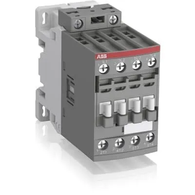
1SBL237287R1400 ABB: The AF26-40-00-14LU is a 4-pole - 600 UL contactor with screw terminals, dedicated for UL lighting applications. Thanks to the AF technology, the contactor has a wide control voltage range (250-500 V 50/60 Hz and DC), managing large control voltage variations, reducing panel energy consumptions and ensuring distinct operations in unstable networks. Furthermore, surge protection is built-in, offering a compact solution. AF contactors have a block type design, can be easily extended with add-on auxiliary contact blocks and an additional wide range of accessories.
Minimum Order Quantity
1 piece
Data Sheet, Technical Information
1SBC100214C0202 - Main catalog Motor protection and control Manual motor starters, contactors and overload relays (PDF) - Edition 2024
Instructions and Manuals
Installation instructions AF(C)09...38(Z)(B) Contactors, NF(C)(Z)(B)22...80E Contactor relays and CA4, CAL4, CAT4, CC4, LDC4 Accessories
Instructions and Manuals (Part 2)
Contactors and Overload relays guide
CAD Dimensional Drawing
Information - 2D and 3D files for CAD systems
Product Net Width
45 mm
Product Net Depth / Length
101 mm
Product Net Height
86 mm
Product Net Weight
0.4 kg
Number of Main Contacts NO
4
Number of Main Contacts NC
0
Number of Auxiliary Contacts NO
0
Number of Auxiliary Contacts NC
0
Number of Poles
4P
Standards
IEC/EN 60947-1, IEC/EN 60947-4-1, UL 60335-2-40 LZGH2 A2L, UL 508, CSA C22.2 No. 60335-2-40 LZGH2 A2L, CSA C22.2 No. 60947-4-1
Rated Operational Voltage
Main Circuit 690 V
Rated Frequency (f)
Control Circuit 50 / 60 Hz | Main Circuit 50 / 60 Hz
Conventional Free-air Thermal Current (Ith)
acc. to IEC 60947-4-1, Open Contactors Θ = 40 °C 55 A
Rated Operational Current AC-1 (Ie)
(690 V) 40 °C 45 A | (690 V) 60 °C 40 A | (690 V) 70 °C 32 A
Rated Operational Current AC-3 (Ie)
(415 V) 60 °C 21.2 A | (440 V) 60 °C 20 A | (500 V) 60 °C 17.6 A | (690 V) 60 °C 10.5 A | (380 / 400 V) 60 °C 22 A | (220 / 230 / 240 V) 60 °C 23.2 A
Rated Operational Power AC-3 (Pe)
(400 V) 11 kW | (415 V) 11 kW | (440 V) 11 kW | (500 V) 11 kW | (690 V) 9 kW | (220 / 230 / 240 V) 5.5 kW
Rated Short-time Withstand Current Low Voltage (Icw)
at 40 °C Ambient Temp, in Free Air, from a Cold State 10 s 300 A | at 40 °C Ambient Temp, in Free Air, from a Cold State 15 min 55 A | at 40 °C Ambient Temp, in Free Air, from a Cold State 1 min 150 A | at 40 °C Ambient Temp, in Free Air, from a Cold State 1 s 450 A | at 40 °C Ambient Temp, in Free Air, from a Cold State 30 s 225 A
Rated Insulation Voltage (Ui)
acc. to IEC 60947-4-1 690 V | acc. to UL/CSA 600 V
Rated Impulse Withstand Voltage (Uimp)
6 kV
Maximum Electrical Switching Frequency
(AC-1) 600 cycles per hour
Maximum Mechanical Switching Frequency
3600 cycles per hour
Rated Control Circuit Voltage (Uc)
50 Hz 250 ... 500 V | 60 Hz 250 ... 500 V | DC Operation 250 ... 500 V
Power Loss
at Rated Operating Conditions AC-1 per Pole 1.6 W | at Rated Operating Conditions AC-3 per Pole 0.42 W
Operate Time
Between Coil De-energization and NC Contact Closing 13 ... 98 ms | Between Coil De-energization and NO Contact Opening 11 ... 95 ms | Between Coil Energization and NC Contact Opening 38 ... 90 ms | Between Coil Energization and NO Contact Closing 40 ... 95 ms
Mounting on DIN Rail
TH35-15 (35 x 15 mm Mounting Rail) acc. to IEC 60715 | TH35-7.5 (35 x 7.5 mm Mounting Rail) acc. to IEC 60715
Mounting by Screws (not supplied)
2 x M4 screws placed diagonally
Connecting Capacity Main Circuit
Flexible with Ferrule 1/2x 1.5 ... 16 mm² | Flexible with Insulated Ferrule 1/2x 1.5 ... 16 mm² | Rigid Solid 1/2x 1.5 ... 4 mm² | Rigid Stranded 1/2x 1.5 ... 16 mm²
Connecting Capacity Control Circuit
Flexible with Ferrule 1/2x 0.75 ... 2.5 mm² | Flexible with Insulated Ferrule 1x 0.75 ... 2.5 mm² | Flexible with Insulated Ferrule 2x 0.75 ... 1.5 mm² | Rigid Solid 1/2x 1 ... 2.5 mm² | Rigid Stranded 1/2x 1 ... 2.5 mm²
Wire Stripping Length
Control Circuit 10 mm | Main Circuit 12 mm
Degree of Protection
acc. to IEC 60529, IEC 60947-1, EN 60529 Coil Terminals IP20 | acc. to IEC 60529, IEC 60947-1, EN 60529 Main Terminals IP20
Tightening Torque
Control Circuit 1.2 N·m | Main Circuit 2.5 N·m
Terminal Type
Screw Terminals
Product Name
Block Contactor
Maximum Operating Voltage UL/CSA
Main Circuit 600 V
General Use Rating UL/CSA
(600 V AC) 45 A
Connecting Capacity Main Circuit UL/CSA
Rigid Solid 1/2x 16-10 AWG | Rigid Stranded 1/2x 16-6 AWG
Connecting Capacity Control Circuit UL/CSA
Rigid Solid 1/2x 18-14 AWG | Rigid Stranded 1/2x 18-14 AWG
Tightening Torque UL/CSA
Control Circuit 11 in·lb | Main Circuit 22 in·lb
Ambient Air Temperature
Close to Contactor for Storage -60 ... +80 °C | Near Contactor for Operation in Free Air -40 ... 70 °C
Climatic Withstand
Category B according to IEC 60947-1 Annex Q
Maximum Operating Altitude Permissible
Without Derating 3000 m
Resistance to Shock acc. to IEC 60068-2-27
Closed, Shock Direction: B1 25 g | Open, Shock Direction: B1 5 g | Shock Direction: A 30 g | Shock Direction: B2 15 g | Shock Direction: C1 25 g | Shock Direction: C2 25 g
Resistance to Vibrations
4g Closed Position & 2g Open position 5 ... 300 Hz
Pollution Degree
3
Conflict Minerals Reporting Template (CMRT)
CMRT - Conflict Minerals Reporting Template
REACH Declaration
REACH - Letter of Confirmation for block contactors, contactor relays, installation contactors, mini contactors, mini contactor relays, thermal overload relays, electronic overload relays and related accessories
RoHS Information
RoHS II declaration for block contactors, installation contactors, mini contactors, mini contactor relays, thermal overload relays, electronic overload relays and related accessories
RoHS Status
Following EU Directive 2011/65/EU and Amendment 2015/863 July 22, 2019
Toxic Substances Control Act - TSCA
Toxic Substances Control Act (TSCA) declaration for Contactors
WEEE B2C / B2B
Business To Business
WEEE Category
5. Small Equipment (No External Dimension More Than 50 cm)
End Of Life Disassembling Instructions
End of life instruction AF(S)09/12/16/26/30/38(Z)(B)(K)(RT) Contactors & NF(Z)(B)(K)(RT) Contactors relays
Sustainable Material Content in Packaging (wt. %)
Recycled Cardboard - 86 %
Sustainable Material Content in Product (wt. %)
Recycled Metal - 28 %
A2L Certificate – UL
UL-US A2L LZGH2 Certificate of Compliance AF09 ... AF38 3-pole contactors with screw terminals - UL 60335-2-40 Household and Similar Electrical Appliances - Safety - Part 2-40: Particular Requirements for Electrical Heat Pumps, Air-Conditioners and Dehumidifiers | UL-CA A2L LZGH2 Certificate of Compliance AF09 ... AF38 3-pole contactors with screw terminals - CSA C22.2 No. 60335-2-40 Household and Similar Electrical Appliances - Safety - Part 2-40: Particular Requirements for Electrical Heat Pumps, Air-Conditioners and Dehumidifiers
CB Certificate
CB Certificate AF(C)26, AF(C)38, AF26(Z)B, AF38(Z)B 4-pole contactors
Declaration of Conformity - CE
EU Declaration of Conformity AF09..LU ... AF80..LU 3 and 4-pole contactors
Declaration of Conformity - UKCA
UK Declaration of Conformity AF09..LU ... AF80..LU 3 and 4-pole contactors
UL Certificate
UL_20180227_E312527_7_1
Package Level 1 Units
box 1 piece
Package Level 1 Width
87 mm
Package Level 1 Depth / Length
103 mm
Package Level 1 Height
47 mm
Package Level 1 Gross Weight
0.4 kg
Package Level 1 EAN
3471523020641
Package Level 2 Units
box 18 piece
Package Level 2 Width
250 mm
Package Level 2 Depth / Length
300 mm
Package Level 2 Height
315 mm
Package Level 2 Gross Weight
14.4 kg
Package Level 3 Units
864 piece
Object Classification Code
Q
ETIM 7
EC000066 - Power contactor, AC switching
ETIM 8
EC000066 - Power contactor, AC switching
ETIM 9
EC000066 - Power contactor, AC switching
eClass
V11.0 : 27371003
UNSPSC
39121529
IDEA Granular Category Code (IGCC)
4760 >> Lighting Contactors
Feature: Wide control voltage range of 250 to 500 V AC, DC operation and built‑in surge protection. Business Impact: Ensures reliable coil energization across fluctuating supply conditions, reducing nuisance trips and energy waste. Application: Ideal for UL lighting and motor control circuits where supply stability varies in manufacturing environments. Long‑tail keywords: AF contactors, 250–500 V control, DC operation, surge protection, UL lighting. Feature: 4‑pole, 4 NO main contacts with a compact block design. Business Impact: Enables robust three‑phase load switching with space‑efficient panel integration. Application: Used in AC‑3 applications up to 22 A and higher‑demand lighting circuits. Long‑tail keywords: 4P contactor, block contactor, AC‑3 rating. Feature: Built‑in surge protection and modular compatibility for add‑on auxiliary blocks. Business Impact: Reduces external protection components and simplifies future expansion. Application: Flexible when extending control logic in evolving control panels. Long‑tail keywords: surge protection built‑in, auxiliary contact blocks, modular accessories. Feature: DIN rail mounting options and screw terminal connections. Business Impact: Eases installation and servicing, improves reliability with secure terminations. Application: Ideal for panel builders using TH35‑15 or TH35‑7.5 rails and conventional screw wiring. Long‑tail keywords: TH35 mounting, DIN rail compatibility, screw terminals. Feature: Broad electrical ratings and protective features. Business Impact: Delivers predictable performance across diverse environments, supporting compliance and lifecycle optimization. Application: Suitable for up to 690 V mains, with IP20 protection and 6 kV impulse withstand. Long‑tail keywords: IEC 60947‑4‑1, rated insulation voltage 690 V, IP20, 6 kV Uimp. Feature: Compact weight and dimensional footprint. Business Impact: Reduces panel footprint and material costs, enabling tighter control enclosures. Application: Where space is at a premium, yet performance must remain high. Long‑tail keywords: 0.4 kg weight, 45 mm width, 101 mm depth, 86 mm height.
Get a Quick Quote for a ABB 1SBL237287R1400
Chat with us on WhatsApp - fast responses guaranteed
Need to speak with someone? We'll call you back within 2 hours during business hours
Interested in ABB 1SBL237287R1400?
Enquire Now
FAQs
The device supports DIN rail mounting using TH35‑15 or TH35‑7.5 rails, providing a secure, standards‑compliant installation. If mounting with screws, use two M4 screws placed diagonally per ABB guidelines. This dual mounting approach helps installers choose the fastest, most reliable method for panel layouts and access for servicing.
The coil accepts 250–500 V across 50 Hz, 60 Hz, or DC operation, while the main circuit is rated up to 690 V. The contactor has four NO main contacts (4P), suitable for AC‑1 and AC‑3 duty, with ratings that support typical 3‑phase loads and UL lighting control scenarios, ensuring dependable performance in varying loads.
Yes, it is designed for UL lighting applications and complies with IEC/EN 60947‑1, IEC/EN 60947‑4‑1, UL 60335‑2‑40, UL 508, CSA C22.2 No. 60335‑2‑40, plus CE and UKCA declarations. This broad certification suite supports global deployment in compliant control panels and ensures the device meets safety and performance expectations.
Main circuit connections support rigid and flexible conductors up to the specified cross‑section, with tightening torque of 2.5 N·m for the main circuit and 1.2 N·m for the control circuit. Control terminals use screw connections, and the unit provides IP20 protection, ensuring reliable electrical interfaces in standard panel environments.
The device’s wide 250–500 V control range reduces wiring changes and simplifies inventory, while built‑in surge protection lowers external protection needs. With a compact footprint and low coil power (1.6 W per pole under AC‑1), installation and maintenance costs drop, delivering faster commissioning and ongoing energy‑use savings over typical panel upgrades.