ABB 1SBL276005R2100 Block Contactor - 690V IEC 60947-4-1
Part Number: 1SBL276005R2100
Quick Summary
ABB 1SBL276005R2100 Block Contactor is a motor control device for starting and stopping industrial motors. In harsh plant environments, voltage fluctuations can cause nuisance trips and inconsistent motor operation; this design tolerates wide control voltages and includes surge protection to maintain reliable control. It complies with IEC/EN 60947-1, IEC/EN 60947-4-1 and UL/CSA standards, with CE declarations, ensuring global compatibility. The unit is DIN-rail mountable and ready for modular expansion with auxiliary blocks, delivering compact, energy-efficient control in modern panels. For OEMs and maintenance teams, this means easier integration, faster commissioning and lower total cost of ownership for motor control and protection.
Product Information
Extended Description
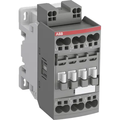
1SBL276005R2100 ABB: The AF30Z-30-00K-21 is a 3 pole - 690 V IEC or 600 UL contactor with Push-in spring terminals, controlling motors up to 15 kW / 400 V AC (AC-3) or 20 hp / 480 V UL and switching power circuits up to 50 A (AC-1) or 50 A UL general use. Thanks to the AF technology, the contactor has a wide control voltage range (24-60 V 50/60 Hz and 20-60 V DC), managing large control voltage variations, reducing panel energy consumptions and ensuring distinct operations in unstable networks. Furthermore, surge protection is built-in, offering a compact solution. AF contactors have a block type design, can be easily extended with add-on auxiliary contact blocks and an additional wide range of accessories.
Minimum Order Quantity
1 piece
Data Sheet, Technical Information
1SBC100214C0202 - Main catalog Motor protection and control Manual motor starters, contactors and overload relays (PDF) - Edition 2024
Instructions and Manuals
Installation instructions AF(C)09...38(Z)(B)..K Contactors, NF(C)(Z)(B)..K Contactor relays and CA4..K, CAL4..K, LDC4K Accessories
Instructions and Manuals (Part 2)
Contactors and Overload relays guide
CAD Dimensional Drawing
Information - 2D and 3D files for CAD systems
Product Net Width
45 mm
Product Net Depth / Length
86 mm
Product Net Height
92.3 mm
Product Net Weight
0.36 kg
Number of Main Contacts NO
3
Number of Main Contacts NC
0
Number of Auxiliary Contacts NO
0
Number of Auxiliary Contacts NC
0
Number of Poles
3P
Standards
IEC/EN 60947-1, IEC/EN 60947-4-1, UL 60947-4-1, CSA C22.2 No. 60947-4-1
Rated Operational Voltage
Main Circuit 690 V
Rated Frequency (f)
Control Circuit 50 / 60 Hz | Main Circuit 50 / 60 Hz
Conventional Free-air Thermal Current (Ith)
acc. to IEC 60947-4-1, Open Contactors Θ = 40 °C 50 A
Rated Operational Current AC-1 (Ie)
(690 V) 40 °C 50 A | (690 V) 60 °C 42 A | (690 V) 70 °C 37 A
Rated Operational Current AC-3 (Ie)
(415 V) 60 °C 32 A | (440 V) 60 °C 32 A | (500 V) 60 °C 28 A | (690 V) 60 °C 21 A | (380 / 400 V) 60 °C 32 A | (220 / 230 / 240 V) 60 °C 33 A
Rated Operational Current AC-3e (Ie)
(415 V) 60 °C 32 A | (440 V) 60 °C 32 A | (500 V) 60 °C 28 A | (690 V) 60 °C 21 A | (380 / 400 V) 60 °C 32 A | (220 / 230 / 240 V) 60 °C 33 A
Rated Operational Current DC-1 (Ie)
(110 V) 2 Poles in Series, 40 °C 50 A | (110 V) 2 Poles in Series, 60 °C 42 A | (110 V) 2 Poles in Series, 70 °C 37 A | (110 V) 3 Poles in Series, 40 °C 50 A | (110 V) 3 Poles in Series, 60 °C 42 A | (110 V) 3 Poles in Series, 70 °C 37 A | (220 V) 3 Poles in Series, 40 °C 50 A | (220 V) 3 Poles in Series, 60 °C 42 A | (220 V) 3 Poles in Series, 70 °C 37 A | (72 V) 1-Pole, 40 °C 50 A | (72 V) 1-Pole, 60 °C 42 A | (72 V) 1-Pole, 70 °C 37 A | (72 V) 2 Poles in Series, 40 °C 50 A | (72 V) 2 Poles in Series, 60 °C 42 A | (72 V) 2 Poles in Series, 70 °C 37 A | (72 V) 3 Poles in Series, 40 °C 50 A | (72 V) 3 Poles in Series, 60 °C 42 A | (72 V) 3 Poles in Series, 70 °C 37 A
Rated Operational Current DC-3 (Ie)
(110 V) 2 Poles in Series, 40 °C 50 A | (110 V) 2 Poles in Series, 60 °C 42 A | (110 V) 2 Poles in Series, 70 °C 37 A | (110 V) 3 Poles in Series, 40 °C 50 A | (110 V) 3 Poles in Series, 60 °C 42 A | (110 V) 3 Poles in Series, 70 °C 37 A | (220 V) 3 Poles in Series, 40 °C 50 A | (220 V) 3 Poles in Series, 60 °C 42 A | (220 V) 3 Poles in Series, 70 °C 37 A | (72 V) 1-Pole, 40 °C 50 A | (72 V) 1-Pole, 60 °C 42 A | (72 V) 1-Pole, 70 °C 37 A | (72 V) 2 Poles in Series, 40 °C 50 A | (72 V) 2 Poles in Series, 60 °C 42 A | (72 V) 2 Poles in Series, 70 °C 37 A | (72 V) 3 Poles in Series, 40 °C 50 A | (72 V) 3 Poles in Series, 60 °C 42 A | (72 V) 3 Poles in Series, 70 °C 37 A
Rated Operational Current DC-5 (Ie)
(110 V) 2 Poles in Series, 40 °C 50 A | (110 V) 2 Poles in Series, 60 °C 42 A | (110 V) 2 Poles in Series, 70 °C 37 A | (110 V) 3 Poles in Series, 40 °C 50 A | (110 V) 3 Poles in Series, 60 °C 42 A | (110 V) 3 Poles in Series, 70 °C 37 A | (220 V) 3 Poles in Series, 40 °C 25 A | (220 V) 3 Poles in Series, 60 °C 25 A | (220 V) 3 Poles in Series, 70 °C 25 A | (72 V) 1-Pole, 40 °C 25 A | (72 V) 1-Pole, 60 °C 25 A | (72 V) 1-Pole, 70 °C 25 A | (72 V) 2 Poles in Series, 40 °C 50 A | (72 V) 2 Poles in Series, 60 °C 42 A | (72 V) 2 Poles in Series, 70 °C 37 A | (72 V) 3 Poles in Series, 40 °C 50 A | (72 V) 3 Poles in Series, 60 °C 42 A | (72 V) 3 Poles in Series, 70 °C 37 A
Rated Operational Power AC-3 (Pe)
(415 V) 15 kW | (440 V) 18.5 kW | (500 V) 18.5 kW | (690 V) 18.5 kW | (380 / 400 V) 15 kW | (220 / 230 / 240 V) 9 kW
Rated Operational Power AC-3e (Pe)
(415 V) 15 kW | (440 V) 18.5 kW | (500 V) 18.5 kW | (690 V) 18.5 kW | (380 / 400 V) 15 kW | (220 / 230 / 240 V) 9 kW
Rated Short-time Withstand Current Low Voltage (Icw)
at 40 °C Ambient Temp, in Free Air, from a Cold State 10 s 350 A | at 40 °C Ambient Temp, in Free Air, from a Cold State 15 min 50 A | at 40 °C Ambient Temp, in Free Air, from a Cold State 1 min 150 A | at 40 °C Ambient Temp, in Free Air, from a Cold State 1 s 700 A | at 40 °C Ambient Temp, in Free Air, from a Cold State 30 s 225 A
Maximum Breaking Capacity
cos phi=0.45 (cos phi=0.35 for Ie > 100 A) at 440 V 500 A | cos phi=0.45 (cos phi=0.35 for Ie > 100 A) at 690 V 200 A
Rated Insulation Voltage (Ui)
acc. to IEC 60947-4-1 690 V | acc. to UL/CSA 600 V
Rated Impulse Withstand Voltage (Uimp)
6 kV
Maximum Electrical Switching Frequency
(AC-1) 600 cycles per hour | (AC-2 / AC-4) 150 cycles per hour | (AC-3) 1200 cycles per hour
Maximum Mechanical Switching Frequency
3600 cycles per hour
Rated Control Circuit Voltage (Uc)
50 Hz 24 ... 60 V | 60 Hz 24 ... 60 V | DC Operation 20 ... 60 V
Power Loss
at Rated Operating Conditions AC-1 per Pole 2.44 W | at Rated Operating Conditions AC-3 per Pole 1 W
Operate Time
Between Coil De-energization and NC Contact Closing 13 ... 98 ms | Between Coil De-energization and NO Contact Opening 11 ... 95 ms | Between Coil Energization and NC Contact Opening 38 ... 90 ms | Between Coil Energization and NO Contact Closing 40 ... 95 ms
Mounting on DIN Rail
TH35-15 (35 x 15 mm Mounting Rail) acc. to IEC 60715 | TH35-7.5 (35 x 7.5 mm Mounting Rail) acc. to IEC 60715
Mounting by Screws (not supplied)
2 x M4 screws placed diagonally
Connecting Capacity Main Circuit
Flexible with Ferrule 1/2x 1 ... 6 mm² | Flexible with Insulated Ferrule 1/2x 1 ... 6 mm² | Flexible 1/2x 1 ... 6 mm² | Rigid Solid 1/2x 1 ... 2.5 mm² | Rigid Stranded 1/2x 4 ... 10 mm²
Connecting Capacity Control Circuit
Flexible with Ferrule 1/2x 0.5 ... 2.5 mm² | Flexible with Insulated Ferrule 1/2x 0.5 ... 1.5 mm² | Flexible 1/2x 0.5 ... 2.5 mm² | Rigid 1/2x 1 ... 2.5 mm² | Rigid Solid 1/2x 1 ... 2.5 mm²
Wire Stripping Length
Control Circuit 10 mm | Main Circuit 14 mm
Degree of Protection
acc. to IEC 60529, IEC 60947-1, EN 60529 Coil Terminals IP20 | acc. to IEC 60529, IEC 60947-1, EN 60529 Main Terminals IP20
Terminal Type
Push-in Spring Terminals
Product Name
Block Contactor
Maximum Operating Voltage UL/CSA
Main Circuit 600 V
General Use Rating UL/CSA
(600 V AC) 45 A
Horsepower Rating UL/CSA
(120 V AC) Single Phase 2 hp | (200 ... 208 V AC) Three Phase 10 hp | (220 ... 240 V AC) Three Phase 10 hp | (240 V AC) Single Phase 5 hp | (440 ... 480 V AC) Three Phase 20 hp | (550 ... 600 V AC) Three Phase 25 hp
Connecting Capacity Main Circuit UL/CSA
Rigid Solid 1/2x 18-14 AWG | Rigid Stranded 1/2x 18-8 AWG
Connecting Capacity Control Circuit UL/CSA
Rigid Solid 1/2x 18-14 AWG
Full Load Amps Motor Use
(120 V AC) Single Phase 24 A | (200 ... 208 V AC) Three Phase 32.2 A | (220 ... 240 V AC) Three Phase 28 A | (240 V AC) Single Phase 28 A | (440 ... 480 V AC) Three Phase 27 A | (550 ... 600 V AC) Three Phase 27 A
Ambient Air Temperature
Close to Contactor without Thermal O/L Relay -40 ... 70 °C | Close to Contactor for Storage -60 ... +80 °C
Climatic Withstand
acc. to IEC 60068-2-30 and 60068-2-11 - UTE C 63-100 specification II
Maximum Operating Altitude Permissible
Without Derating 3000 m
Resistance to Vibrations
4g Closed Position & 2g Open position 5 ... 300 Hz
Pollution Degree
3
Conflict Minerals Reporting Template (CMRT)
CMRT - Conflict Minerals Reporting Template
REACH Declaration
REACH - Letter of Confirmation for block contactors, contactor relays, installation contactors, mini contactors, mini contactor relays, thermal overload relays, electronic overload relays and related accessories
RoHS Information
RoHS II declaration for block contactors, installation contactors, mini contactors, mini contactor relays, thermal overload relays, electronic overload relays and related accessories
RoHS Status
Following EU Directive 2011/65/EU and Amendment 2015/863 July 22, 2019
Toxic Substances Control Act - TSCA
Toxic Substances Control Act (TSCA) declaration for Contactors
WEEE B2C / B2B
Business To Business
WEEE Category
5. Small Equipment (No External Dimension More Than 50 cm)
End Of Life Disassembling Instructions
End of life instruction AF(S)09/12/16/26/30/38(Z)(B)(K)(RT) Contactors & NF(Z)(B)(K)(RT) Contactors relays
Environmental Product Declaration - EPD
Environmental Product Declaration AF(S)26/30/38(Z)(B) Contactors (FR)
Sustainable Material Content in Packaging (wt. %)
Recycled Cardboard - 86 %
Sustainable Material Content in Product (wt. %)
Recycled Metal - 28 %
ABS Certificate
ABS Certificate, AF(S)09 to AF(S)96 contactors, NF contactor relays and CA4, CC4, CAL4, CAT4 auxiliary contact blocks, TEF4 electronic timers
CB Certificate
CB Certificate AF26(Z)(B), AF30(Z)(B), AF(Z)(B)38 3-pole contactors, AFS26, AFS30, AFS38 safety contactors
CCC Certificate
CCC Certificate AF26, AF30, AF38, AF26(Z)B, AF30(Z)B, AF38(Z)B 3 and 4-pole contactors, AFS26, AFS30, AFS38 safety contactors
CQC Certificate
CQC Certificate, Contactor, AF*26, AF*30, AF*38, Made in France | CQC Certificate, Contactor, AF26,AF30,AF38, Made in China
Declaration of Conformity - CCC
CCC Declaration of Conformity, Contactor, AF26, AF30, AF38, AFS26, AFS30, AFS38 Made in France | CCC Declaration of Conformity, Contactor, AF26, AF30, AF38, Made in China
Declaration of Conformity - CE
EU Declaration of Conformity AF09... AF96-30-.., AF09...38(Z)-30..K 3-pole Contactors
Declaration of Conformity - UKCA
UK Declaration of Conformity AF09... AF96-30-.., AF09...38(Z)-30..K 3-pole Contactors
DNV Certificate
DNV Certificate AF(S)09...96 3-pole & AF09...80 4-pole contactors with screw, spring, push-in terminals
LR Certificate
LRS Certificate AF(S)09..(K) ... AF96 3 and 4-pole contactors and CA(L)4..(K), CAT4, CC4 auxiliary contact blocks
RINA Certificate
Rina Certificate for AF(S)09...AF(S)96 contactors, NF contactor relays and accessories with screw,spring and push-in terminals
RMRS Certificate
RMRS Certificate AF(S)09(S)...AF(S)38 3-pole and 4-pole, AF(S)40..96 3-pole contactors with screw, push-in and spring terminals
UL Certificate
UL-US Certificate of Compliance AF(C)(S)09(R/M/N)-..(L)(S)(K)...AF(C)(S)38(R/M/N)..(K) 3-pole contactors screw, spring and push-in spring terminals; LDC4 additional coil terminal block; LF16-4, LG16-4, LF38-4 and LH38-4 connecting strips, LD38-4 additional terminal block | UL-CA Certificate of Compliance AF(C)(S)09(R/M/N)-..(L)(S)(K)...AF(C)(S)38(R/M/N)..(K) 3-pole contactors screw, spring and push-in spring terminals; LDC4 additional coil terminal block; LF16-4, LG16-4, LF38-4 and LH38-4 connecting strips, LD38-4 additional terminal block
Package Level 1 Units
box 1 piece
Package Level 1 Width
93 mm
Package Level 1 Depth / Length
86 mm
Package Level 1 Height
45 mm
Package Level 1 Gross Weight
0.375 kg
Package Level 1 EAN
3471523156616
Package Level 2 Units
box 21 piece
Package Level 2 Width
250 mm
Package Level 2 Depth / Length
300 mm
Package Level 2 Height
315 mm
Package Level 2 Gross Weight
16.875 kg
Package Level 3 Units
1080 piece
Object Classification Code
Q
ETIM 7
EC000066 - Power contactor, AC switching
ETIM 8
EC000066 - Power contactor, AC switching
ETIM 9
EC000066 - Power contactor, AC switching
eClass
V11.0 : 27371003
UNSPSC
39121529
IDEA Granular Category Code (IGCC)
4758 >> Iec Contactors
E-Number (Finland)
3707926
E-Number (Sweden)
3210622
Feature 3-pole design with a 690 V main circuit and AC-3 rating up to 18.5 kW enables direct control of standard motors in many applications. Business Impact enables reliable switching for frequently started loads while supporting a compact, space-efficient panel design. Application suitable for conveyors, pumps, and fans in industrial environments. Feature AF technology delivers a wide control voltage range of 24-60 Hz and 20-60 V DC, allowing the coil to tolerate large voltage variations. Business Impact reduces nuisance trips and stabilizes operation in networks with fluctuating supply. Application ideal where control supply is derived from unreliable sources or when multiple control voltages are in use. Feature built-in surge protection and a robust block-design that can be extended with add-on auxiliary contact blocks. Business Impact minimizes space and wiring while enabling modular expansion to accommodate additional signaling without new enclosures. Application scalable motor protection and control for evolving systems on factory floors. Feature Push-in spring terminals for fast wiring and a coil terminal arrangement designed for safe, compact installation. Business Impact reduces installation labor and improves termination reliability in tight control cabinets. Application panel builders and maintenance teams benefit from quicker commissioning. Feature DIN rail mounting TH35-15 or TH35-7.5; mechanical footprint and mounting options simplify retrofits and new installations. Business Impact streamlines installation in standard switchgear and reduces mounting time. Application control cabinets with limited depth and standardized DIN rails. Feature Compliance with IEC/EN 60947-1, IEC/EN 60947-4-1, UL 60947-4-1, CSA C22.2 No. 60947-4-1; CE declarations. Business Impact ensures global acceptance for multi-site deployments and regulatory adherence. Application equipment designed for international plants with safety approvals across regions.
Get a Quick Quote for a ABB 1SBL276005R2100
Chat with us on WhatsApp - fast responses guaranteed
Need to speak with someone? We'll call you back within 2 hours during business hours
Interested in ABB 1SBL276005R2100?
Enquire Now
FAQs
Install on a TH35 DIN rail (TH35-15 or TH35-7.5) in a compliant control cabinet. Mounting screws are 2 x M4 placed diagonally, and ensure coil terminals are IP20 protected. Use the push-in spring terminals for main and control circuits to speed up wiring and improve reliability.
Rated Operational Current AC-3 at 690 V is 21 A (60 °C) and 32 A at 440–500–690 V variants; AC-1 current is 50 A at 690 V (varies with temperature). This supports motor loads up to 15 kW (AC-3) at applicable voltages, with continuous operation and appropriate derating for higher ambient temperatures.
Yes. The device provides AC-3 rated power up to 15 kW at 380–400 V and up to 18.5 kW at higher voltages such as 440–690 V, making it suitable for common 3-phase motor applications in manufacturing lines, conveyors, and pumps with appropriate enclosure and wiring.
It complies with IEC/EN 60947-1 and 60947-4-1, UL 60947-4-1, and CSA C22.2. CE declarations cover EU compliance, with UL/CSA listings supporting North American use. Additional CB, CCC, and other declarations are available for multi-region deployments.
AF technology provides a wide coil voltage tolerance, reducing control-circuit disturbances and energy waste in fluctuating networks. With coil power loss around 2.44 W per pole (AC-1) and surge protection, the solution lowers panel energy consumption, improves reliability, and reduces maintenance time, improving total cost of ownership in long-running automation lines.