ABB 1SBL277001R1122 Block Contactor - CE UL/CSA
Part Number: 1SBL277001R1122
Quick Summary
ABB 1SBL277001R1122 Block Contactor delivers robust motor control for industrial machines. In panels with fluctuating control voltages, energization stability remains a common pain point that can cause nuisance trips and wasted energy. It carries CE and UL/CSA certifications with an IP20 enclosure, supporting global safety and installation standards. The AF technology enables a wide control voltage range, and it is designed for DIN-rail mounting on TH35 rails with add-on auxiliary blocks for future expansion. This combination helps minimize panel footprint, reduce wiring complexity, and deliver reliable, scalable motor control across diverse applications.
Product Information
Extended Description
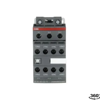
1SBL277001R1122 ABB: The AF30-30-22-11 is a 3 pole - 690 V IEC or 600 UL contactor with pre-mounted auxiliary contacts and screw terminals, controlling motors up to 15 kW / 400 V AC (AC-3) or 20 hp / 480 V UL and switching power circuits up to 50 A (AC-1) or 50 A UL general use. Thanks to the AF technology, the contactor has a wide control voltage range (24-60 V 50/60 Hz and 20-60 V DC), managing large control voltage variations, reducing panel energy consumptions and ensuring distinct operations in unstable networks. Furthermore, surge protection is built-in, offering a compact solution. AF contactors have a block type design, can be easily extended with add-on auxiliary contact blocks and an additional wide range of accessories.
Minimum Order Quantity
1 piece
Data Sheet, Technical Information
1SBC100214C0202 - Main catalog Motor protection and control Manual motor starters, contactors and overload relays (PDF) - Edition 2024
Instructions and Manuals
Installation instructions AF(C)09...38(Z)(B) Contactors, NF(C)(Z)(B)22...80E Contactor relays and CA4, CAL4, CAT4, CC4, LDC4 Accessories
Instructions and Manuals (Part 2)
Contactors and Overload relays guide
CAD Dimensional Drawing
Information - 2D and 3D files for CAD systems
Product Net Width
45 mm
Product Net Depth / Length
119.5 mm
Product Net Height
86 mm
Product Net Weight
0.36 kg
Number of Main Contacts NO
3
Number of Main Contacts NC
0
Number of Auxiliary Contacts NO
2
Number of Auxiliary Contacts NC
2
Number of Poles
3P
Standards
IEC/EN 60947-1, IEC/EN 60947-4-1, UL 60335-2-40 LZGH2 A2L, UL 60947-4-1, CSA C22.2 No. 60335-2-40 LZGH2 A2L, CSA C22.2 No. 60947-4-1
Rated Operational Voltage
Auxiliary Circuit 690 V | Main Circuit 690 V
Rated Frequency (f)
Auxiliary Circuit 50 / 60 Hz | Control Circuit 50 / 60 Hz | Main Circuit 50 / 60 Hz
Conventional Free-air Thermal Current (Ith)
acc. to IEC 60947-4-1, Open Contactors Θ = 40 °C 50 A | acc. to IEC 60947-5-1, Θ = 40 °C 16 A
Rated Operational Current AC-1 (Ie)
(690 V) 40 °C 50 A | (690 V) 60 °C 42 A | (690 V) 70 °C 37 A
Rated Operational Current AC-3 (Ie)
(415 V) 60 °C 32 A | (440 V) 60 °C 32 A | (500 V) 60 °C 28 A | (690 V) 60 °C 21 A | (380 / 400 V) 60 °C 32 A | (220 / 230 / 240 V) 60 °C 33 A
Rated Operational Current AC-3e (Ie)
(415 V) 60 °C 32 A | (440 V) 60 °C 32 A | (500 V) 60 °C 28 A | (690 V) 60 °C 21 A | (380 / 400 V) 60 °C 32 A | (220 / 230 / 240 V) 60 °C 33 A
Rated Operational Current AC-15 (Ie)
(500 V) 2 A | (690 V) 2 A | (24 / 127 V) 6 A | (220 / 240 V) 4 A | (400 / 440 V) 3 A
Rated Operational Current DC-1 (Ie)
(110 V) 2 Poles in Series, 40 °C 50 A | (110 V) 2 Poles in Series, 60 °C 42 A | (110 V) 2 Poles in Series, 70 °C 37 A | (110 V) 3 Poles in Series, 40 °C 50 A | (110 V) 3 Poles in Series, 60 °C 42 A | (110 V) 3 Poles in Series, 70 °C 37 A | (220 V) 3 Poles in Series, 40 °C 50 A | (220 V) 3 Poles in Series, 60 °C 42 A | (220 V) 3 Poles in Series, 70 °C 37 A | (72 V) 1-Pole, 40 °C 50 A | (72 V) 1-Pole, 60 °C 42 A | (72 V) 1-Pole, 70 °C 37 A | (72 V) 2 Poles in Series, 40 °C 50 A | (72 V) 2 Poles in Series, 60 °C 42 A | (72 V) 2 Poles in Series, 70 °C 37 A | (72 V) 3 Poles in Series, 40 °C 50 A | (72 V) 3 Poles in Series, 60 °C 42 A | (72 V) 3 Poles in Series, 70 °C 37 A
Rated Operational Current DC-3 (Ie)
(110 V) 2 Poles in Series, 40 °C 50 A | (110 V) 2 Poles in Series, 60 °C 42 A | (110 V) 2 Poles in Series, 70 °C 37 A | (110 V) 3 Poles in Series, 40 °C 50 A | (110 V) 3 Poles in Series, 60 °C 42 A | (110 V) 3 Poles in Series, 70 °C 37 A | (220 V) 3 Poles in Series, 40 °C 50 A | (220 V) 3 Poles in Series, 60 °C 42 A | (220 V) 3 Poles in Series, 70 °C 37 A | (72 V) 1-Pole, 40 °C 50 A | (72 V) 1-Pole, 60 °C 42 A | (72 V) 1-Pole, 70 °C 37 A | (72 V) 2 Poles in Series, 40 °C 50 A | (72 V) 2 Poles in Series, 60 °C 42 A | (72 V) 2 Poles in Series, 70 °C 37 A | (72 V) 3 Poles in Series, 40 °C 50 A | (72 V) 3 Poles in Series, 60 °C 42 A | (72 V) 3 Poles in Series, 70 °C 37 A
Rated Operational Current DC-5 (Ie)
(110 V) 2 Poles in Series, 40 °C 50 A | (110 V) 2 Poles in Series, 60 °C 42 A | (110 V) 2 Poles in Series, 70 °C 37 A | (110 V) 3 Poles in Series, 40 °C 50 A | (110 V) 3 Poles in Series, 60 °C 42 A | (110 V) 3 Poles in Series, 70 °C 37 A | (220 V) 3 Poles in Series, 40 °C 25 A | (220 V) 3 Poles in Series, 60 °C 25 A | (220 V) 3 Poles in Series, 70 °C 25 A | (72 V) 1-Pole, 40 °C 25 A | (72 V) 1-Pole, 60 °C 25 A | (72 V) 1-Pole, 70 °C 25 A | (72 V) 2 Poles in Series, 40 °C 50 A | (72 V) 2 Poles in Series, 60 °C 42 A | (72 V) 2 Poles in Series, 70 °C 37 A | (72 V) 3 Poles in Series, 40 °C 50 A | (72 V) 3 Poles in Series, 60 °C 42 A | (72 V) 3 Poles in Series, 70 °C 37 A
Rated Operational Current DC-13 (Ie)
(24 V) 6 A / 144 W | (48 V) 2.8 A / 134 W | (72 V) 1 A / 72 W | (110 V) 0.55 A / 60 W | (125 V) 0.55 A / 69 W | (220 V) 0.27 A / 60 W | (250 V) 0.27 A / 68 W | (400 V) 0.15 A / 60 W | (500 V) 0.13 A / 65 W | (600 V) 0.1 A / 60 W
Rated Operational Power AC-3 (Pe)
(400 V) 15 kW | (415 V) 15 kW | (440 V) 18.5 kW | (500 V) 18.5 kW | (690 V) 18.5 kW | (380 / 400 V) 15 kW | (220 / 230 / 240 V) 9 kW
Rated Operational Power AC-3e (Pe)
(415 V) 15 kW | (440 V) 18.5 kW | (500 V) 18.5 kW | (690 V) 18.5 kW | (380 / 400 V) 15 kW | (220 / 230 / 240 V) 9 kW
Rated Short-time Withstand Current Low Voltage (Icw)
at 40 °C Ambient Temp, in Free Air, from a Cold State 10 s 350 A | at 40 °C Ambient Temp, in Free Air, from a Cold State 15 min 50 A | at 40 °C Ambient Temp, in Free Air, from a Cold State 1 min 150 A | at 40 °C Ambient Temp, in Free Air, from a Cold State 1 s 700 A | at 40 °C Ambient Temp, in Free Air, from a Cold State 30 s 225 A | for 0.1 s 140 A | for 1 s 100 A
Maximum Breaking Capacity
cos phi=0.45 (cos phi=0.35 for Ie > 100 A) at 440 V 500 A | cos phi=0.45 (cos phi=0.35 for Ie > 100 A) at 690 V 200 A
Rated Insulation Voltage (Ui)
acc. to IEC 60947-4-1 690 V | acc. to IEC 60947-5-1 690 V | acc. to UL/CSA 600 V
Rated Impulse Withstand Voltage (Uimp)
6 kV
Maximum Electrical Switching Frequency
(AC-1) 600 cycles per hour | (AC-15) 1200 cycles per hour | (AC-2 / AC-4) 150 cycles per hour | (AC-3) 1200 cycles per hour | (DC-13) 900 cycles per hour
Maximum Mechanical Switching Frequency
3600 cycles per hour
Rated Control Circuit Voltage (Uc)
50 Hz 24 ... 60 V | 60 Hz 24 ... 60 V | DC Operation 20 ... 60 V
Power Loss
at 6 A per Pole 0.1 W | at Rated Operating Conditions AC-1 per Pole 2.4 W | at Rated Operating Conditions AC-3 per Pole 0.9 W
Operate Time
Between Coil De-energization and NC Contact Closing 13 ... 98 ms | Between Coil De-energization and NO Contact Opening 11 ... 95 ms | Between Coil Energization and NC Contact Opening 38 ... 90 ms | Between Coil Energization and NO Contact Closing 40 ... 95 ms
Mounting on DIN Rail
TH35-15 (35 x 15 mm Mounting Rail) acc. to IEC 60715 | TH35-7.5 (35 x 7.5 mm Mounting Rail) acc. to IEC 60715
Mounting by Screws (not supplied)
2 x M4 screws placed diagonally
Connecting Capacity Main Circuit
Flexible with Ferrule 1/2x 1.5 ... 10 mm² | Flexible with Insulated Ferrule 1x 1.5 ... 10 mm² | Flexible with Insulated Ferrule 2x 1.5 ... 4 mm² | Rigid Solid 1/2x 2.5 ... 4 mm² | Rigid Stranded 1/2x 2.5 ... 10 mm²
Connecting Capacity Auxiliary Circuit
Flexible with Ferrule 1/2x 0.75 ... 2.5 mm² | Flexible with Insulated Ferrule 1x 0.75 ... 2.5 mm² | Flexible with Insulated Ferrule 2x 0.75 ... 1.5 mm² | Rigid Solid 1/2x 1 ... 2.5 mm² | Rigid Stranded 1/2x 1 ... 2.5 mm²
Connecting Capacity Control Circuit
Flexible with Ferrule 1/2x 0.75 ... 2.5 mm² | Flexible with Insulated Ferrule 1x 0.75 ... 2.5 mm² | Flexible with Insulated Ferrule 2x 0.75 ... 1.5 mm² | Rigid Solid 1/2x 1 ... 2.5 mm² | Rigid Stranded 1/2x 1 ... 2.5 mm²
Wire Stripping Length
Auxiliary Circuit 10 mm | Control Circuit 10 mm | Main Circuit 14 mm
Degree of Protection
acc. to IEC 60529, IEC 60947-1, EN 60529 Auxiliary Terminals IP20 | acc. to IEC 60529, IEC 60947-1, EN 60529 Coil Terminals IP20 | acc. to IEC 60529, IEC 60947-1, EN 60529 Main Terminals IP20
Tightening Torque
Auxiliary Circuit 1.2 N·m | Control Circuit 1.2 N·m | Main Circuit 2.5 N·m
Terminal Type
Screw Terminals
Product Name
Block Contactor
Maximum Operating Voltage UL/CSA
Main Circuit 600 V
General Use Rating UL/CSA
(600 V AC) 50 A
Horsepower Rating UL/CSA
(120 V AC) Single Phase 2 hp | (200 ... 208 V AC) Three Phase 10 hp | (220 ... 240 V AC) Three Phase 10 hp | (240 V AC) Single Phase 5 hp | (440 ... 480 V AC) Three Phase 20 hp | (550 ... 600 V AC) Three Phase 25 hp
Connecting Capacity Main Circuit UL/CSA
Rigid Solid 1/2x 14-10 AWG | Rigid Stranded 1/2x 14-8 AWG
Connecting Capacity Auxiliary Circuit UL/CSA
Rigid Solid 1/2x 18-14 AWG | Rigid Stranded 1/2x 18-14 AWG
Connecting Capacity Control Circuit UL/CSA
Rigid Solid 1/2x 18-14 AWG | Rigid Stranded 1/2x 18-14 AWG
Tightening Torque UL/CSA
Auxiliary Circuit 11 in·lb | Control Circuit 11 in·lb | Main Circuit 22 in·lb
Full Load Amps Motor Use
(120 V AC) Single Phase 24 A | (200 ... 208 V AC) Three Phase 32.2 A | (220 ... 240 V AC) Three Phase 28 A | (240 V AC) Single Phase 28 A | (440 ... 480 V AC) Three Phase 27 A | (550 ... 600 V AC) Three Phase 27 A
Ambient Air Temperature
Close to Contactor Fitted with Thermal O/L Relay -25 ... 60 °C | Close to Contactor without Thermal O/L Relay -40 ... 70 °C | Close to Contactor for Storage -60 ... +80 °C
Climatic Withstand
acc. to IEC 60068-2-30 and 60068-2-11 - UTE C 63-100 specification II
Maximum Operating Altitude Permissible
Without Derating 3000 m
Resistance to Shock acc. to IEC 60068-2-27
Closed, Shock Direction: B1 25 g | Open, Shock Direction: B1 5 g | Shock Direction: A 30 g | Shock Direction: B2 15 g | Shock Direction: C1 25 g | Shock Direction: C2 25 g
Resistance to Vibrations
4g Closed Position & 2g Open position 5 ... 300 Hz
Pollution Degree
3
Conflict Minerals Reporting Template (CMRT)
CMRT - Conflict Minerals Reporting Template
REACH Declaration
REACH - Letter of Confirmation for block contactors, contactor relays, installation contactors, mini contactors, mini contactor relays, thermal overload relays, electronic overload relays and related accessories
RoHS Information
RoHS II declaration for block contactors, installation contactors, mini contactors, mini contactor relays, thermal overload relays, electronic overload relays and related accessories
RoHS Status
Following EU Directive 2011/65/EU and Amendment 2015/863 July 22, 2019
Toxic Substances Control Act - TSCA
Toxic Substances Control Act (TSCA) declaration for Contactors
WEEE B2C / B2B
Business To Business
WEEE Category
5. Small Equipment (No External Dimension More Than 50 cm)
End Of Life Disassembling Instructions
End of life instruction AF(S)09/12/16/26/30/38(Z)(B)(K)(RT) Contactors & NF(Z)(B)(K)(RT) Contactors relays
Environmental Product Declaration - EPD
Environmental Product Declaration AF(S)26/30/38(Z)(B) Contactors (FR)
Sustainable Material Content in Packaging (wt. %)
Recycled Cardboard - 86 %
Sustainable Material Content in Product (wt. %)
Recycled Metal - 28 %
A2L Certificate – UL
UL-US A2L LZGH2 Certificate of Compliance AF09 ... AF38 3-pole contactors with screw terminals - UL 60335-2-40 Household and Similar Electrical Appliances - Safety - Part 2-40: Particular Requirements for Electrical Heat Pumps, Air-Conditioners and Dehumidifiers | UL-CA A2L LZGH2 Certificate of Compliance AF09 ... AF38 3-pole contactors with screw terminals - CSA C22.2 No. 60335-2-40 Household and Similar Electrical Appliances - Safety - Part 2-40: Particular Requirements for Electrical Heat Pumps, Air-Conditioners and Dehumidifiers
ABS Certificate
ABS Certificate, AF(S)09 to AF(S)96 contactors, NF contactor relays and CA4, CC4, CAL4, CAT4 auxiliary contact blocks, TEF4 electronic timers
BV Certificate
BV Certificate AF(C)09...AF(C)38 3-pole and 4-pole contactors with screw and Push-in Spring terminals
CB Certificate
CB Certificate AF26(Z)(B), AF30(Z)(B), AF(Z)(B)38 3-pole contactors, AFS26, AFS30, AFS38 safety contactors
CCC Certificate
CCC Certificate AF26, AF30, AF38, AF26(Z)B, AF30(Z)B, AF38(Z)B 3 and 4-pole contactors, AFS26, AFS30, AFS38 safety contactors
CQC Certificate
CQC Certificate, Contactor, AF*26, AF*30, AF*38, Made in France | CQC Certificate, Contactor, AF26,AF30,AF38, Made in China
Declaration of Conformity - CCC
CCC Declaration of Conformity, Contactor, AF26, AF30, AF38, AFS26, AFS30, AFS38 Made in France | CCC Declaration of Conformity, Contactor, AF26, AF30, AF38, Made in China
Declaration of Conformity - CE
EU Declaration of Conformity AF09... AF96-30-.., AF09...38(Z)-30..K 3-pole Contactors
Declaration of Conformity - UKCA
UK Declaration of Conformity AF09... AF96-30-.., AF09...38(Z)-30..K 3-pole Contactors
DNV Certificate
DNV Certificate AF(S)09...96 3-pole & AF09...80 4-pole contactors with screw, spring, push-in terminals
GOST Certificate
GOST_POCCFR.ME77.B07175.pdf
KC Certificate
KC Certificate AF26...AF38 3-pole contactors
LR Certificate
LRS Certificate AF(S)09..(K) ... AF96 3 and 4-pole contactors and CA(L)4..(K), CAT4, CC4 auxiliary contact blocks
RINA Certificate
Rina Certificate for AF(S)09...AF(S)96 contactors, NF contactor relays and accessories with screw,spring and push-in terminals
RMRS Certificate
RMRS Certificate AF(S)09(S)...AF(S)38 3-pole and 4-pole, AF(S)40..96 3-pole contactors with screw, push-in and spring terminals
UL Certificate
UL-US Certificate of Compliance AF(C)(S)09(R/M/N)-..(L)(S)(K)...AF(C)(S)38(R/M/N)..(K) 3-pole contactors screw, spring and push-in spring terminals; LDC4 additional coil terminal block; LF16-4, LG16-4, LF38-4 and LH38-4 connecting strips, LD38-4 additional terminal block | UL-CA Certificate of Compliance AF(C)(S)09(R/M/N)-..(L)(S)(K)...AF(C)(S)38(R/M/N)..(K) 3-pole contactors screw, spring and push-in spring terminals; LDC4 additional coil terminal block; LF16-4, LG16-4, LF38-4 and LH38-4 connecting strips, LD38-4 additional terminal block
UL Listing Card
E312527
Package Level 1 Units
box 1 piece
Package Level 1 Width
87 mm
Package Level 1 Depth / Length
121 mm
Package Level 1 Height
47 mm
Package Level 1 Gross Weight
0.36 kg
Package Level 1 EAN
3471523111417
Package Level 2 Units
box 18 piece
Package Level 2 Width
250 mm
Package Level 2 Depth / Length
300 mm
Package Level 2 Height
315 mm
Package Level 2 Gross Weight
12.96 kg
Package Level 3 Units
864 piece
Object Classification Code
Q
ETIM 7
EC000066 - Power contactor, AC switching
ETIM 8
EC000066 - Power contactor, AC switching
ETIM 9
EC000066 - Power contactor, AC switching
eClass
V11.0 : 27371003
UNSPSC
39121529
IDEA Granular Category Code (IGCC)
4758 >> Iec Contactors
Feature AF technology with a wide control voltage range and built-in surge protection → Business Impact Reduced risk of misoperation and trips in networks with voltage variation, leading to lower maintenance costs and improved line uptime. Application in motor protection and control across conveyors, pumps, and machine tools. Feature 3-pole main contacts with 2 NO + 2 NC auxiliary contacts and screw terminals → Business Impact Enables straightforward wiring for both main circuits and auxiliary signaling, improving installation speed and reducing terminal faults. Application Suitable for IEC 60947-4-1/60947-5-1 compliant systems, with easy integration into existing control schemas. Feature DIN rail mounting compatibility (TH35-15 or TH35-7.5) and block-type design → Business Impact Simplifies panel layout, allows rapid upgrades, and supports scalable automation architectures. Application Ideal for modular machine assemblies and retrofit projects. Feature Low power loss (0.1 W per pole at test conditions) and defined coil ranges (24–60 V AC, 50/60 Hz; 20–60 V DC) → Business Impact Reduces coil energy consumption and heat generation in panels, improving overall energy efficiency and reliability. Application Beneficial in energy-conscious facilities and compact control panels. Feature Comprehensive protection (IP20, UL/CSA, CE) and pre-mounted auxiliary blocks → Business Impact Ensures compliance, reduces the need for additional protective components, and accelerates installation in regulated environments. Application Supports international deployments and cross-market servicing.
Get a Quick Quote for a ABB 1SBL277001R1122
Chat with us on WhatsApp - fast responses guaranteed
Need to speak with someone? We'll call you back within 2 hours during business hours
Interested in ABB 1SBL277001R1122?
Enquire Now
FAQs
Install on standard TH35 DIN rails (TH35-15 or TH35-7.5) for secure mounting and quick replacement. For the main circuit, use flexible copper conductors sized to 1/2x 2.5-10 mm² or rigid 1/2x 2.5-4 mm², tightened to 2.5 N·m. For the auxiliary circuit, use 0.75-2.5 mm² conductors and tighten to 1.2 N·m. Plan space for add-on auxiliary contact blocks during layout.
The device provides three main contacts with two NO and two NC auxiliaries. In AC‑3 operation at 690 V, it is rated around 21 A (60 °C). In AC‑1, it can reach about 42 A at 690 V. Rated power for AC‑3e ranges near 18.5 kW for 440–690 V, with 15 kW at 400–415 V. These ratings guide motor matching and protection.
Yes. The coil supports 24–60 V AC at 50/60 Hz and 20–60 V DC, covering most plant control voltages. The design includes built‑in surge protection, reducing the need for external suppressors and enhancing reliability in networks with transient spikes or intermittent supply quality.
The product is CE and UL/CSA certified, with IP20 protection on terminals. It is designed to meet IEC/EN 60947-1 and 60947-4-1 standards for contactors, along with UL/CAN listings for North American safety requirements. UKCA is also indicated in documentation, supporting multi-market deployment with aligned conformity across regions.
AF technology affords a wide control voltage tolerance, reducing voltage‑related wiring issues and improving reliability in unstable networks, which translates to fewer trips and lower maintenance costs. Built‑in surge protection minimizes external components, while low coil power (0.1 W per pole) reduces panel heat and overall energy consumption, contributing to measurable energy savings over time.