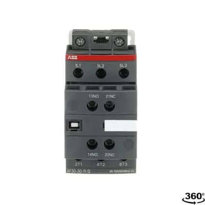
ABB AF30-30-11-12 Contactor - 690V IEC/EN 60947-4-1
Part Number: 1SBL277001R1211
Quick Summary
The ABB AF30-30-11-12 Contactor delivers reliable motor control for industrial panel applications. It is a 3-pole device designed for mains voltages up to 690 V and a wide control voltage range of 48–130 V, AC or DC. This design helps manage voltage fluctuations and reduces nuisance trips in unstable networks. The AF technology provides compact dimensions and built-in surge protection, enabling stable operation in tight control cabinets. With CE, UL/CSA, and IP20 protection, it supports safe, compliant installations. Its block-type design permits easy expansion with auxiliary contact blocks, while DIN-rail mounting and screw-terminal connections simplify installation and commissioning. In short, it combines reliability, flexibility and energy efficiency for demanding automation environments.
Product Information
Extended Description
1SBL277001R1211 ABB: The AF30-30-11-12 is a 3 pole - 690 V IEC or 600 UL contactor with pre-mounted auxiliary contacts and screw terminals, controlling motors up to 15 kW / 400 V AC (AC-3) or 20 hp / 480 V UL and switching power circuits up to 50 A (AC-1) or 50 A UL general use. Thanks to the AF technology, the contactor has a wide control voltage range (48-130 V 50/60 Hz and DC), managing large control voltage variations, reducing panel energy consumptions and ensuring distinct operations in unstable networks. Furthermore, surge protection is built-in, offering a compact solution. AF contactors have a block type design, can be easily extended with add-on auxiliary contact blocks and an additional wide range of accessories.
Minimum Order Quantity
1 piece
Data Sheet, Technical Information
1SBC100214C0202 - Main catalog Motor protection and control Manual motor starters, contactors and overload relays (PDF) - Edition 2024
Instructions and Manuals
Installation instructions AF(C)09...38(Z)(B) Contactors, NF(C)(Z)(B)22...80E Contactor relays and CA4, CAL4, CAT4, CC4, LDC4 Accessories
Instructions and Manuals (Part 2)
Contactors and Overload relays guide
CAD Dimensional Drawing
Information - 2D and 3D files for CAD systems
Product Net Width
45 mm
Product Net Depth / Length
111.5 mm
Product Net Height
86 mm
Product Net Weight
0.35 kg
Number of Main Contacts NO
3
Number of Main Contacts NC
0
Number of Auxiliary Contacts NO
1
Number of Auxiliary Contacts NC
1
Number of Poles
3P
Standards
IEC/EN 60947-1, IEC/EN 60947-4-1, UL 60335-2-40 LZGH2 A2L, UL 60947-4-1, CSA C22.2 No. 60335-2-40 LZGH2 A2L, CSA C22.2 No. 60947-4-1
Rated Operational Voltage
Auxiliary Circuit 690 V | Main Circuit 690 V
Rated Frequency (f)
Auxiliary Circuit 50 / 60 Hz | Control Circuit 50 / 60 Hz | Main Circuit 50 / 60 Hz
Conventional Free-air Thermal Current (Ith)
acc. to IEC 60947-4-1, Open Contactors Θ = 40 °C 50 A | acc. to IEC 60947-5-1, Θ = 40 °C 16 A
Rated Operational Current AC-1 (Ie)
(690 V) 40 °C 50 A | (690 V) 60 °C 42 A | (690 V) 70 °C 37 A
Rated Operational Current AC-3 (Ie)
(415 V) 60 °C 32 A | (440 V) 60 °C 32 A | (500 V) 60 °C 28 A | (690 V) 60 °C 21 A | (380 / 400 V) 60 °C 32 A | (220 / 230 / 240 V) 60 °C 33 A
Rated Operational Current AC-3e (Ie)
(415 V) 60 °C 32 A | (440 V) 60 °C 32 A | (500 V) 60 °C 28 A | (690 V) 60 °C 21 A | (380 / 400 V) 60 °C 32 A | (220 / 230 / 240 V) 60 °C 33 A
Rated Operational Current AC-15 (Ie)
(500 V) 2 A | (690 V) 2 A | (24 / 127 V) 6 A | (220 / 240 V) 4 A | (400 / 440 V) 3 A
Rated Operational Current DC-1 (Ie)
(110 V) 2 Poles in Series, 40 °C 50 A | (110 V) 2 Poles in Series, 60 °C 42 A | (110 V) 2 Poles in Series, 70 °C 37 A | (110 V) 3 Poles in Series, 40 °C 50 A | (110 V) 3 Poles in Series, 60 °C 42 A | (110 V) 3 Poles in Series, 70 °C 37 A | (220 V) 3 Poles in Series, 40 °C 50 A | (220 V) 3 Poles in Series, 60 °C 42 A | (220 V) 3 Poles in Series, 70 °C 37 A | (72 V) 1-Pole, 40 °C 50 A | (72 V) 1-Pole, 60 °C 42 A | (72 V) 1-Pole, 70 °C 37 A | (72 V) 2 Poles in Series, 40 °C 50 A | (72 V) 2 Poles in Series, 60 °C 42 A | (72 V) 2 Poles in Series, 70 °C 37 A | (72 V) 3 Poles in Series, 40 °C 50 A | (72 V) 3 Poles in Series, 60 °C 42 A | (72 V) 3 Poles in Series, 70 °C 37 A
Rated Operational Current DC-3 (Ie)
(110 V) 2 Poles in Series, 40 °C 50 A | (110 V) 2 Poles in Series, 60 °C 42 A | (110 V) 2 Poles in Series, 70 °C 37 A | (110 V) 3 Poles in Series, 40 °C 50 A | (110 V) 3 Poles in Series, 60 °C 42 A | (110 V) 3 Poles in Series, 70 °C 37 A | (220 V) 3 Poles in Series, 40 °C 50 A | (220 V) 3 Poles in Series, 60 °C 42 A | (220 V) 3 Poles in Series, 70 °C 37 A | (72 V) 1-Pole, 40 °C 50 A | (72 V) 1-Pole, 60 °C 42 A | (72 V) 1-Pole, 70 °C 37 A | (72 V) 2 Poles in Series, 40 °C 50 A | (72 V) 2 Poles in Series, 60 °C 42 A | (72 V) 2 Poles in Series, 70 °C 37 A | (72 V) 3 Poles in Series, 40 °C 50 A | (72 V) 3 Poles in Series, 60 °C 42 A | (72 V) 3 Poles in Series, 70 °C 37 A
Rated Operational Current DC-5 (Ie)
(110 V) 2 Poles in Series, 40 °C 50 A | (110 V) 2 Poles in Series, 60 °C 42 A | (110 V) 2 Poles in Series, 70 °C 37 A | (110 V) 3 Poles in Series, 40 °C 50 A | (110 V) 3 Poles in Series, 60 °C 42 A | (110 V) 3 Poles in Series, 70 °C 37 A | (220 V) 3 Poles in Series, 40 °C 25 A | (220 V) 3 Poles in Series, 60 °C 25 A | (220 V) 3 Poles in Series, 70 °C 25 A | (72 V) 1-Pole, 40 °C 25 A | (72 V) 1-Pole, 60 °C 25 A | (72 V) 1-Pole, 70 °C 25 A | (72 V) 2 Poles in Series, 40 °C 50 A | (72 V) 2 Poles in Series, 60 °C 42 A | (72 V) 2 Poles in Series, 70 °C 37 A | (72 V) 3 Poles in Series, 40 °C 50 A | (72 V) 3 Poles in Series, 60 °C 42 A | (72 V) 3 Poles in Series, 70 °C 37 A
Rated Operational Current DC-13 (Ie)
(24 V) 6 A / 144 W | (48 V) 2.8 A / 134 W | (72 V) 1 A / 72 W | (110 V) 0.55 A / 60 W | (125 V) 0.55 A / 69 W | (220 V) 0.27 A / 60 W | (250 V) 0.27 A / 68 W | (400 V) 0.15 A / 60 W | (500 V) 0.13 A / 65 W | (600 V) 0.1 A / 60 W
Rated Operational Power AC-3 (Pe)
(400 V) 15 kW | (415 V) 15 kW | (440 V) 18.5 kW | (500 V) 18.5 kW | (690 V) 18.5 kW | (380 / 400 V) 15 kW | (220 / 230 / 240 V) 9 kW
Rated Operational Power AC-3e (Pe)
(415 V) 15 kW | (440 V) 18.5 kW | (500 V) 18.5 kW | (690 V) 18.5 kW | (380 / 400 V) 15 kW | (220 / 230 / 240 V) 9 kW
Rated Short-time Withstand Current Low Voltage (Icw)
at 40 °C Ambient Temp, in Free Air, from a Cold State 10 s 350 A | at 40 °C Ambient Temp, in Free Air, from a Cold State 15 min 50 A | at 40 °C Ambient Temp, in Free Air, from a Cold State 1 min 150 A | at 40 °C Ambient Temp, in Free Air, from a Cold State 1 s 700 A | at 40 °C Ambient Temp, in Free Air, from a Cold State 30 s 225 A | for 0.1 s 140 A | for 1 s 100 A
Maximum Breaking Capacity
cos phi=0.45 (cos phi=0.35 for Ie > 100 A) at 440 V 500 A | cos phi=0.45 (cos phi=0.35 for Ie > 100 A) at 690 V 200 A
Rated Insulation Voltage (Ui)
acc. to IEC 60947-4-1 690 V | acc. to IEC 60947-5-1 690 V | acc. to UL/CSA 600 V
Rated Impulse Withstand Voltage (Uimp)
6 kV
Maximum Electrical Switching Frequency
(AC-1) 600 cycles per hour | (AC-15) 1200 cycles per hour | (AC-2 / AC-4) 150 cycles per hour | (AC-3) 1200 cycles per hour | (DC-13) 900 cycles per hour
Maximum Mechanical Switching Frequency
3600 cycles per hour
Rated Control Circuit Voltage (Uc)
50 Hz 48 ... 130 V | 60 Hz 48 ... 130 V | DC Operation 48 ... 130 V
Power Loss
at 6 A per Pole 0.1 W | at Rated Operating Conditions AC-1 per Pole 2.4 W | at Rated Operating Conditions AC-3 per Pole 0.9 W
Operate Time
Between Coil De-energization and NC Contact Closing 13 ... 98 ms | Between Coil De-energization and NO Contact Opening 11 ... 95 ms | Between Coil Energization and NC Contact Opening 38 ... 90 ms | Between Coil Energization and NO Contact Closing 40 ... 95 ms
Mounting on DIN Rail
TH35-15 (35 x 15 mm Mounting Rail) acc. to IEC 60715 | TH35-7.5 (35 x 7.5 mm Mounting Rail) acc. to IEC 60715
Mounting by Screws (not supplied)
2 x M4 screws placed diagonally
Connecting Capacity Main Circuit
Flexible with Ferrule 1/2x 1.5 ... 10 mm² | Flexible with Insulated Ferrule 1x 1.5 ... 10 mm² | Flexible with Insulated Ferrule 2x 1.5 ... 4 mm² | Rigid Solid 1/2x 2.5 ... 4 mm² | Rigid Stranded 1/2x 2.5 ... 10 mm²
Connecting Capacity Auxiliary Circuit
Flexible with Ferrule 1/2x 0.75 ... 2.5 mm² | Flexible with Insulated Ferrule 1x 0.75 ... 2.5 mm² | Flexible with Insulated Ferrule 2x 0.75 ... 1.5 mm² | Rigid Solid 1/2x 1 ... 2.5 mm² | Rigid Stranded 1/2x 1 ... 2.5 mm²
Connecting Capacity Control Circuit
Flexible with Ferrule 1/2x 0.75 ... 2.5 mm² | Flexible with Insulated Ferrule 1x 0.75 ... 2.5 mm² | Flexible with Insulated Ferrule 2x 0.75 ... 1.5 mm² | Rigid Solid 1/2x 1 ... 2.5 mm² | Rigid Stranded 1/2x 1 ... 2.5 mm²
Wire Stripping Length
Auxiliary Circuit 10 mm | Control Circuit 10 mm | Main Circuit 14 mm
Degree of Protection
acc. to IEC 60529, IEC 60947-1, EN 60529 Auxiliary Terminals IP20 | acc. to IEC 60529, IEC 60947-1, EN 60529 Coil Terminals IP20 | acc. to IEC 60529, IEC 60947-1, EN 60529 Main Terminals IP20
Tightening Torque
Auxiliary Circuit 1.2 N·m | Control Circuit 1.2 N·m | Main Circuit 2.5 N·m
Terminal Type
Screw Terminals
Product Name
Block Contactor
Maximum Operating Voltage UL/CSA
Main Circuit 600 V
General Use Rating UL/CSA
(600 V AC) 50 A
Horsepower Rating UL/CSA
(120 V AC) Single Phase 2 hp | (200 ... 208 V AC) Three Phase 10 hp | (220 ... 240 V AC) Three Phase 10 hp | (240 V AC) Single Phase 5 hp | (440 ... 480 V AC) Three Phase 20 hp | (550 ... 600 V AC) Three Phase 25 hp
Connecting Capacity Main Circuit UL/CSA
Rigid Solid 1/2x 14-10 AWG | Rigid Stranded 1/2x 14-8 AWG
Connecting Capacity Auxiliary Circuit UL/CSA
Rigid Solid 1/2x 18-14 AWG | Rigid Stranded 1/2x 18-14 AWG
Connecting Capacity Control Circuit UL/CSA
Rigid Solid 1/2x 18-14 AWG | Rigid Stranded 1/2x 18-14 AWG
Tightening Torque UL/CSA
Auxiliary Circuit 11 in·lb | Control Circuit 11 in·lb | Main Circuit 22 in·lb
Full Load Amps Motor Use
(120 V AC) Single Phase 24 A | (200 ... 208 V AC) Three Phase 32.2 A | (220 ... 240 V AC) Three Phase 28 A | (240 V AC) Single Phase 28 A | (440 ... 480 V AC) Three Phase 27 A | (550 ... 600 V AC) Three Phase 27 A
Ambient Air Temperature
Close to Contactor Fitted with Thermal O/L Relay -25 ... 60 °C | Close to Contactor without Thermal O/L Relay -40 ... 70 °C | Close to Contactor for Storage -60 ... +80 °C
Climatic Withstand
acc. to IEC 60068-2-30 and 60068-2-11 - UTE C 63-100 specification II
Maximum Operating Altitude Permissible
Without Derating 3000 m
Resistance to Shock acc. to IEC 60068-2-27
Closed, Shock Direction: B1 25 g | Open, Shock Direction: B1 5 g | Shock Direction: A 30 g | Shock Direction: B2 15 g | Shock Direction: C1 25 g | Shock Direction: C2 25 g
Resistance to Vibrations
4g Closed Position & 2g Open position 5 ... 300 Hz
Pollution Degree
3
Conflict Minerals Reporting Template (CMRT)
CMRT - Conflict Minerals Reporting Template
REACH Declaration
REACH - Letter of Confirmation for block contactors, contactor relays, installation contactors, mini contactors, mini contactor relays, thermal overload relays, electronic overload relays and related accessories
RoHS Information
RoHS II declaration for block contactors, installation contactors, mini contactors, mini contactor relays, thermal overload relays, electronic overload relays and related accessories
RoHS Status
Following EU Directive 2011/65/EU and Amendment 2015/863 July 22, 2019
Toxic Substances Control Act - TSCA
Toxic Substances Control Act (TSCA) declaration for Contactors
WEEE B2C / B2B
Business To Business
WEEE Category
5. Small Equipment (No External Dimension More Than 50 cm)
End Of Life Disassembling Instructions
End of life instruction AF(S)09/12/16/26/30/38(Z)(B)(K)(RT) Contactors & NF(Z)(B)(K)(RT) Contactors relays
Environmental Product Declaration - EPD
Environmental Product Declaration AF(S)26/30/38(Z)(B) Contactors (FR)
Sustainable Material Content in Packaging (wt. %)
Recycled Cardboard - 86 %
Sustainable Material Content in Product (wt. %)
Recycled Metal - 28 %
A2L Certificate – UL
UL-US A2L LZGH2 Certificate of Compliance AF09 ... AF38 3-pole contactors with screw terminals - UL 60335-2-40 Household and Similar Electrical Appliances - Safety - Part 2-40: Particular Requirements for Electrical Heat Pumps, Air-Conditioners and Dehumidifiers | UL-CA A2L LZGH2 Certificate of Compliance AF09 ... AF38 3-pole contactors with screw terminals - CSA C22.2 No. 60335-2-40 Household and Similar Electrical Appliances - Safety - Part 2-40: Particular Requirements for Electrical Heat Pumps, Air-Conditioners and Dehumidifiers
ABS Certificate
ABS Certificate, AF(S)09 to AF(S)96 contactors, NF contactor relays and CA4, CC4, CAL4, CAT4 auxiliary contact blocks, TEF4 electronic timers
BV Certificate
BV Certificate AF(C)09...AF(C)38 3-pole and 4-pole contactors with screw and Push-in Spring terminals
CB Certificate
CB Certificate AF26(Z)(B), AF30(Z)(B), AF(Z)(B)38 3-pole contactors, AFS26, AFS30, AFS38 safety contactors
CCC Certificate
CCC Certificate AF26, AF30, AF38, AF26(Z)B, AF30(Z)B, AF38(Z)B 3 and 4-pole contactors, AFS26, AFS30, AFS38 safety contactors
CQC Certificate
CQC Certificate, Contactor, AF*26, AF*30, AF*38, Made in France | CQC Certificate, Contactor, AF26,AF30,AF38, Made in China
Declaration of Conformity - CCC
CCC Declaration of Conformity, Contactor, AF26, AF30, AF38, AFS26, AFS30, AFS38 Made in France | CCC Declaration of Conformity, Contactor, AF26, AF30, AF38, Made in China
Declaration of Conformity - CE
EU Declaration of Conformity AF09... AF96-30-.., AF09...38(Z)-30..K 3-pole Contactors
Declaration of Conformity - UKCA
UK Declaration of Conformity AF09... AF96-30-.., AF09...38(Z)-30..K 3-pole Contactors
DNV Certificate
DNV Certificate AF(S)09...96 3-pole & AF09...80 4-pole contactors with screw, spring, push-in terminals
GOST Certificate
GOST_POCCFR.ME77.B07175.pdf
KC Certificate
KC Certificate AF26...AF38 3-pole contactors
LR Certificate
LRS Certificate AF(S)09..(K) ... AF96 3 and 4-pole contactors and CA(L)4..(K), CAT4, CC4 auxiliary contact blocks
RINA Certificate
Rina Certificate for AF(S)09...AF(S)96 contactors, NF contactor relays and accessories with screw,spring and push-in terminals
RMRS Certificate
RMRS Certificate AF(S)09(S)...AF(S)38 3-pole and 4-pole, AF(S)40..96 3-pole contactors with screw, push-in and spring terminals
UL Certificate
UL-US Certificate of Compliance AF(C)(S)09(R/M/N)-..(L)(S)(K)...AF(C)(S)38(R/M/N)..(K) 3-pole contactors screw, spring and push-in spring terminals; LDC4 additional coil terminal block; LF16-4, LG16-4, LF38-4 and LH38-4 connecting strips, LD38-4 additional terminal block | UL-CA Certificate of Compliance AF(C)(S)09(R/M/N)-..(L)(S)(K)...AF(C)(S)38(R/M/N)..(K) 3-pole contactors screw, spring and push-in spring terminals; LDC4 additional coil terminal block; LF16-4, LG16-4, LF38-4 and LH38-4 connecting strips, LD38-4 additional terminal block
UL Listing Card
E312527
Package Level 1 Units
box 1 piece
Package Level 1 Width
87 mm
Package Level 1 Depth / Length
114 mm
Package Level 1 Height
47 mm
Package Level 1 Gross Weight
0.35 kg
Package Level 1 EAN
3471523111325
Package Level 2 Units
box 18 piece
Package Level 2 Width
250 mm
Package Level 2 Depth / Length
300 mm
Package Level 2 Height
315 mm
Package Level 2 Gross Weight
12.6 kg
Package Level 3 Units
864 piece
Object Classification Code
Q
ETIM 7
EC000066 - Power contactor, AC switching
ETIM 8
EC000066 - Power contactor, AC switching
ETIM 9
EC000066 - Power contactor, AC switching
eClass
V11.0 : 27371003
UNSPSC
39121529
IDEA Granular Category Code (IGCC)
4758 >> Iec Contactors
Feature: Wide control voltage range with AF technology. Benefit: Tolerates large control voltage variations, reducing energy consumption and ensuring dependable operation in networks with voltage swings. Application: Control circuits in conveyors and pumps where supply quality fluctuates. Feature: 3-pole main contacts at 690 V and 50/60 Hz. Benefit: Handles substantial motor loads with predictable performance while supporting AC-3 duty up to 18.5 kW at higher voltages. Application: Heavy-duty motor switching in packaging lines and fans. Feature: Built-in surge protection. Benefit: Shields the coil from voltage spikes, extending device life and reducing maintenance. Application: Panel installations near noisy power sources and in OEM equipment. Feature: Auxiliary contacts (1 NO, 1 NC) integrated. Benefit: Facilitates interlocking and signaling without extra blocks, lowering BOM costs. Application: Start/stop interlocks and control logic in automated equipment. Feature: Modular design with add-on auxiliary blocks. Benefit: Easy expansion to meet evolving control schemes without replacing the base unit. Application: Scalable automation projects and retrofit scenarios. Feature: DIN rail mounting (TH35-15/TH35-7.5) and screw terminals. Benefit: Fast, secure installation with versatile mounting options. Application: Retrofit in existing cabinets and new builds. Feature: Compliance with IEC/EN 60947-1, 60947-4-1 and UL/CSA standards. Benefit: Simplified certification processes and global acceptance. Application: Global manufacturing environments needing robust safety compliance.
Get a Quick Quote for a ABB 1SBL277001R1211
Chat with us on WhatsApp - fast responses guaranteed
Need to speak with someone? We'll call you back within 2 hours during business hours
Interested in ABB 1SBL277001R1211?
Enquire Now
FAQs
The AF30-30-11-12 is designed for DIN-rail mounting using TH35-15 or TH35-7.5 rails. It also supports screw mounting with 2x M4 screws supplied separately. For quick, secure installs, snap it onto a compatible DIN rail in a control cabinet and connect main and auxiliary circuits via screw terminals, ensuring proper torque per specification.
For AC-3 duty, the device supports up to 32 A at 415–440 V, 28 A at 500 V, and 21 A at 690 V. For AC-1 duty, ratings include up to 50 A at 690 V (60 °C) and progressively lower currents at higher temperatures. These values enable correct sizing for motor control in varied voltage configurations.
Yes, the AF30-30-11-12 includes built-in surge protection. This feature safeguards the coil and associated electronics from voltage spikes, reducing nuisance trips, extending component life, and lowering maintenance costs in panels exposed to switching transients and unstable networks.
The contactor complies with IEC/EN 60947-1 and 60947-4-1, UL 60335-2-40 family standards, and UL/CSA listings. It is CE marked and IP20 protected for auxiliary and main terminals, enabling straightforward compliance in diverse global markets and safe installation in typical control cabinets.
At 690 V, the rated operational power for AC-3 is up to 18.5 kW (and corresponding UL/CSA equivalents). This makes the AF30-30-11-12 suitable for medium to high-power motors in industrial settings like conveyors or pumps, while offering reliable switching performance and energy efficiency.