ABB 1SBL277061R1400 Block Contactor - AF Technology
Part Number: 1SBL277061R1400
Quick Summary
ABB 1SBL277061R1400 Block Contactor is a high‑reliability three‑pole switch designed for motor control in industrial equipment. In the field, voltage swings and unstable networks often trigger nuisance trips and energy waste, impacting uptime and operating costs. This device meets IEC 60947‑1, IEC 60947‑4‑1 and UL 60335‑2‑40 requirements, with CE and UKCA declarations to support global adoption. Its compact form factor and versatile mounting options reduce panel footprint while enabling scalable control solutions. By combining AF technology with rugged construction, it delivers measurable value for OEMs and end users seeking reliable performance and lower total cost of ownership.
Product Information
Extended Description
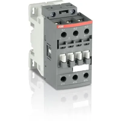
1SBL277061R1400 ABB: The AF30B-30-00-14 is a 3 pole - 690 V IEC or 600 UL contactor with screw terminals, controlling motors up to 15 kW / 400 V AC (AC-3) or 20 hp / 480 V UL and switching power circuits up to 50 A (AC-1) or 50 A UL general use. Thanks to the AF technology, the contactor has a wide control voltage range (250-500 V 50/60 Hz and DC), managing large control voltage variations, reducing panel energy consumptions and ensuring distinct operations in unstable networks. Furthermore, surge protection is built-in, offering a compact solution. AF contactors have a block type design, can be easily extended with add-on auxiliary contact blocks and an additional wide range of accessories.
Minimum Order Quantity
1 piece
Customs Tariff Number
85364900
Data Sheet, Technical Information
Motor control and protection for Rolling stock application_PDF
Instructions and Manuals
Installation instructions AF(C)09...38(Z)(B) Contactors, NF(C)(Z)(B)22...80E Contactor relays and CA4, CAL4, CAT4, CC4, LDC4 Accessories
Instructions and Manuals (Part 2)
Contactors and Overload relays guide
CAD Dimensional Drawing
Information - 2D and 3D files for CAD systems
Product Net Width
45 mm
Product Net Depth / Length
86 mm
Product Net Height
86 mm
Product Net Weight
0.37 kg
Number of Main Contacts NO
3
Number of Main Contacts NC
0
Number of Auxiliary Contacts NO
0
Number of Auxiliary Contacts NC
0
Number of Poles
3P
Standards
IEC/EN 60947-1, IEC/EN 60947-4-1, UL 60335-2-40 LZGH2 A2L, UL 60947-4-1, CSA C22.2 No. 60335-2-40 LZGH2 A2L, CSA C22.2 No. 60947-4-1, IEC 60077-1 (applicable parts), IEC 60077-2 (applicable parts), EN 50155 (applicable parts), TR CU 001/2011, IEC 61373, For compliance confirmation on applicable parts based on your application and combination, please consult your ABB sales representatives.
Rated Operational Voltage
Main Circuit 690 V
Rated Frequency (f)
Control Circuit 50 / 60 Hz | Main Circuit 50 / 60 Hz
Conventional Free-air Thermal Current (Ith)
acc. to IEC 60947-4-1, Open Contactors Θ = 40 °C 50 A
Rated Operational Current AC-1 (Ie)
(690 V) 40 °C 50 A | (690 V) 60 °C 42 A | (690 V) 70 °C 37 A
Rated Operational Current AC-3 (Ie)
(415 V) 60 °C 32 A | (440 V) 60 °C 32 A | (500 V) 60 °C 28 A | (690 V) 60 °C 21 A | (380 / 400 V) 60 °C 32 A | (220 / 230 / 240 V) 60 °C 33 A
Rated Operational Current AC-3e (Ie)
(415 V) 60 °C 32 A | (440 V) 60 °C 32 A | (500 V) 60 °C 28 A | (690 V) 60 °C 21 A | (380 / 400 V) 60 °C 32 A | (220 / 230 / 240 V) 60 °C 33 A
Rated Operational Current DC-1 (Ie)
(110 V) 2 Poles in Series, 40 °C 50 A | (110 V) 2 Poles in Series, 60 °C 42 A | (110 V) 2 Poles in Series, 70 °C 37 A | (110 V) 3 Poles in Series, 40 °C 50 A | (110 V) 3 Poles in Series, 60 °C 42 A | (110 V) 3 Poles in Series, 70 °C 37 A | (220 V) 3 Poles in Series, 40 °C 50 A | (220 V) 3 Poles in Series, 60 °C 42 A | (220 V) 3 Poles in Series, 70 °C 37 A | (72 V) 1-Pole, 40 °C 50 A | (72 V) 1-Pole, 60 °C 42 A | (72 V) 1-Pole, 70 °C 37 A | (72 V) 2 Poles in Series, 40 °C 50 A | (72 V) 2 Poles in Series, 60 °C 42 A | (72 V) 2 Poles in Series, 70 °C 37 A | (72 V) 3 Poles in Series, 40 °C 50 A | (72 V) 3 Poles in Series, 60 °C 42 A | (72 V) 3 Poles in Series, 70 °C 37 A
Rated Operational Current DC-3 (Ie)
(110 V) 2 Poles in Series, 40 °C 50 A | (110 V) 2 Poles in Series, 60 °C 42 A | (110 V) 2 Poles in Series, 70 °C 37 A | (110 V) 3 Poles in Series, 40 °C 50 A | (110 V) 3 Poles in Series, 60 °C 42 A | (110 V) 3 Poles in Series, 70 °C 37 A | (220 V) 3 Poles in Series, 40 °C 50 A | (220 V) 3 Poles in Series, 60 °C 42 A | (220 V) 3 Poles in Series, 70 °C 37 A | (72 V) 1-Pole, 40 °C 50 A | (72 V) 1-Pole, 60 °C 42 A | (72 V) 1-Pole, 70 °C 37 A | (72 V) 2 Poles in Series, 40 °C 50 A | (72 V) 2 Poles in Series, 60 °C 42 A | (72 V) 2 Poles in Series, 70 °C 37 A | (72 V) 3 Poles in Series, 40 °C 50 A | (72 V) 3 Poles in Series, 60 °C 42 A | (72 V) 3 Poles in Series, 70 °C 37 A
Rated Operational Current DC-5 (Ie)
(110 V) 2 Poles in Series, 40 °C 50 A | (110 V) 2 Poles in Series, 60 °C 42 A | (110 V) 2 Poles in Series, 70 °C 37 A | (110 V) 3 Poles in Series, 40 °C 50 A | (110 V) 3 Poles in Series, 60 °C 42 A | (110 V) 3 Poles in Series, 70 °C 37 A | (220 V) 3 Poles in Series, 40 °C 25 A | (220 V) 3 Poles in Series, 60 °C 25 A | (220 V) 3 Poles in Series, 70 °C 25 A | (72 V) 1-Pole, 40 °C 25 A | (72 V) 1-Pole, 60 °C 25 A | (72 V) 1-Pole, 70 °C 25 A | (72 V) 2 Poles in Series, 40 °C 50 A | (72 V) 2 Poles in Series, 60 °C 42 A | (72 V) 2 Poles in Series, 70 °C 37 A | (72 V) 3 Poles in Series, 40 °C 50 A | (72 V) 3 Poles in Series, 60 °C 42 A | (72 V) 3 Poles in Series, 70 °C 37 A
Rated Operational Power AC-3 (Pe)
(415 V) 15 kW | (440 V) 18.5 kW | (500 V) 18.5 kW | (690 V) 18.5 kW | (380 / 400 V) 15 kW | (220 / 230 / 240 V) 9 kW
Rated Operational Power AC-3e (Pe)
(415 V) 15 kW | (440 V) 18.5 kW | (500 V) 18.5 kW | (690 V) 18.5 kW | (380 / 400 V) 15 kW | (220 / 230 / 240 V) 9 kW
Rated Short-time Withstand Current Low Voltage (Icw)
at 40 °C Ambient Temp, in Free Air, from a Cold State 10 s 350 A | at 40 °C Ambient Temp, in Free Air, from a Cold State 15 min 50 A | at 40 °C Ambient Temp, in Free Air, from a Cold State 1 min 150 A | at 40 °C Ambient Temp, in Free Air, from a Cold State 1 s 700 A | at 40 °C Ambient Temp, in Free Air, from a Cold State 30 s 225 A
Maximum Breaking Capacity
cos phi=0.45 (cos phi=0.35 for Ie > 100 A) at 440 V 500 A | cos phi=0.45 (cos phi=0.35 for Ie > 100 A) at 690 V 200 A
Rated Insulation Voltage (Ui)
acc. to IEC 60947-4-1 690 V | acc. to UL/CSA 600 V
Rated Impulse Withstand Voltage (Uimp)
6 kV
Maximum Electrical Switching Frequency
(AC-1) 600 cycles per hour | (AC-2 / AC-4) 150 cycles per hour | (AC-3) 1200 cycles per hour
Maximum Mechanical Switching Frequency
3600 cycles per hour
Rated Control Circuit Voltage (Uc)
50 Hz 250 ... 500 V | 60 Hz 250 ... 500 V | DC Operation 250 ... 500 V
Power Loss
at Rated Operating Conditions AC-1 per Pole 2.4 W | at Rated Operating Conditions AC-3 per Pole 0.9 W
Operate Time
Between Coil De-energization and NC Contact Closing 13 ... 98 ms | Between Coil De-energization and NO Contact Opening 11 ... 95 ms | Between Coil Energization and NC Contact Opening 38 ... 90 ms | Between Coil Energization and NO Contact Closing 40 ... 95 ms
Mounting on DIN Rail
TH35-15 (35 x 15 mm Mounting Rail) acc. to IEC 60715 | TH35-7.5 (35 x 7.5 mm Mounting Rail) acc. to IEC 60715
Mounting by Screws (not supplied)
2 x M4 screws placed diagonally
Connecting Capacity Main Circuit
Flexible with Ferrule 1/2x 1.5 ... 10 mm² | Flexible with Insulated Ferrule 1x 1.5 ... 10 mm² | Flexible with Insulated Ferrule 2x 1.5 ... 4 mm² | Rigid Solid 1/2x 2.5 ... 4 mm² | Rigid Stranded 1/2x 2.5 ... 10 mm²
Connecting Capacity Control Circuit
Flexible with Ferrule 1/2x 0.75 ... 2.5 mm² | Flexible with Insulated Ferrule 1x 0.75 ... 2.5 mm² | Flexible with Insulated Ferrule 2x 0.75 ... 1.5 mm² | Rigid Solid 1/2x 1 ... 2.5 mm² | Rigid Stranded 1/2x 1 ... 2.5 mm²
Wire Stripping Length
Control Circuit 10 mm | Main Circuit 14 mm
Degree of Protection
acc. to IEC 60529, IEC 60947-1, EN 60529 Coil Terminals IP20 | acc. to IEC 60529, IEC 60947-1, EN 60529 Main Terminals IP20
Tightening Torque
Control Circuit 1.2 N·m | Main Circuit 2.5 N·m
Terminal Type
Screw Terminals
Product Name
Block Contactor
Maximum Operating Voltage UL/CSA
Main Circuit 600 V
General Use Rating UL/CSA
(600 V AC) 50 A
Horsepower Rating UL/CSA
(120 V AC) Single Phase 2 hp | (200 ... 208 V AC) Three Phase 10 hp | (220 ... 240 V AC) Three Phase 10 hp | (240 V AC) Single Phase 5 hp | (440 ... 480 V AC) Three Phase 20 hp | (550 ... 600 V AC) Three Phase 25 hp
Connecting Capacity Main Circuit UL/CSA
Rigid Solid 1/2x 14-10 AWG | Rigid Stranded 1/2x 14-8 AWG
Connecting Capacity Control Circuit UL/CSA
Rigid Solid 1/2x 18-14 AWG | Rigid Stranded 1/2x 18-14 AWG
Tightening Torque UL/CSA
Control Circuit 11 in·lb | Main Circuit 22 in·lb
Full Load Amps Motor Use
(120 V AC) Single Phase 24 A | (200 ... 208 V AC) Three Phase 32.2 A | (220 ... 240 V AC) Three Phase 28 A | (240 V AC) Single Phase 28 A | (440 ... 480 V AC) Three Phase 27 A | (550 ... 600 V AC) Three Phase 27 A
Ambient Air Temperature
Close to Contactor Fitted with Thermal O/L Relay -25 ... 60 °C | Close to Contactor without Thermal O/L Relay -40 ... 70 °C | Close to Contactor for Storage -60 ... +80 °C
Climatic Withstand
acc. to IEC 60068-2-30 and 60068-2-11 - UTE C 63-100 specification II
Maximum Operating Altitude Permissible
Without Derating 3000 m
Shock and Vibration Withstand acc. to IEC 61373
Category 1, Class B
Pollution Degree
3
Conflict Minerals Reporting Template (CMRT)
CMRT - Conflict Minerals Reporting Template
REACH Declaration
REACH - Letter of Confirmation for block contactors, contactor relays, installation contactors, mini contactors, mini contactor relays, thermal overload relays, electronic overload relays and related accessories
RoHS Information
RoHS II declaration for block contactors, installation contactors, mini contactors, mini contactor relays, thermal overload relays, electronic overload relays and related accessories
RoHS Status
Following EU Directive 2011/65/EU and Amendment 2015/863 July 22, 2019
Toxic Substances Control Act - TSCA
Toxic Substances Control Act (TSCA) declaration for Contactors
WEEE B2C / B2B
Business To Business
WEEE Category
5. Small Equipment (No External Dimension More Than 50 cm)
End Of Life Disassembling Instructions
End of life instruction AF(S)09/12/16/26/30/38(Z)(B)(K)(RT) Contactors & NF(Z)(B)(K)(RT) Contactors relays
Environmental Product Declaration - EPD
Environmental Product Declaration AF(S)26/30/38(Z)(B) Contactors (FR)
Sustainable Material Content in Packaging (wt. %)
Recycled Cardboard - 86 %
Sustainable Material Content in Product (wt. %)
Recycled Metal - 28 %
A2L Certificate – UL
UL-US A2L LZGH2 Certificate of Compliance AF09 ... AF38 3-pole contactors with screw terminals - UL 60335-2-40 Household and Similar Electrical Appliances - Safety - Part 2-40: Particular Requirements for Electrical Heat Pumps, Air-Conditioners and Dehumidifiers | UL-CA A2L LZGH2 Certificate of Compliance AF09 ... AF38 3-pole contactors with screw terminals - CSA C22.2 No. 60335-2-40 Household and Similar Electrical Appliances - Safety - Part 2-40: Particular Requirements for Electrical Heat Pumps, Air-Conditioners and Dehumidifiers
CB Certificate
CB Certificate AF26(Z)(B), AF30(Z)(B), AF(Z)(B)38 3-pole contactors, AFS26, AFS30, AFS38 safety contactors
CCC Certificate
CCC Certificate AF26, AF30, AF38, AF26(Z)B, AF30(Z)B, AF38(Z)B 3 and 4-pole contactors, AFS26, AFS30, AFS38 safety contactors
CQC Certificate
CQC Certificate, Contactor, AF*26, AF*30, AF*38, Made in France
Declaration of Conformity - CCC
CCC Declaration of Conformity, Contactor, AF26, AF30, AF38, AFS26, AFS30, AFS38 Made in France
Declaration of Conformity - CE
EU Declaration of Conformity AF09 ... AF38(Z)B..(K), AF40B ... AF96B 3 and 4-pole contactors
Declaration of Conformity - UKCA
UK Declaration of Conformity AF09 ... AF38(Z)B..(K), AF40B ... AF96B 3 and 4-pole contactors
GOST Certificate
GOST_POCCFR.ME77.B07175.pdf
KC Certificate
KC Certificate AF26...AF38 3-pole contactors
UL Certificate
UL-US Certificate of Compliance AF(C)(S)09(R/M/N)-..(L)(S)(K)...AF(C)(S)38(R/M/N)..(K) 3-pole contactors screw, spring and push-in spring terminals; LDC4 additional coil terminal block; LF16-4, LG16-4, LF38-4 and LH38-4 connecting strips, LD38-4 additional terminal block | UL-CA Certificate of Compliance AF(C)(S)09(R/M/N)-..(L)(S)(K)...AF(C)(S)38(R/M/N)..(K) 3-pole contactors screw, spring and push-in spring terminals; LDC4 additional coil terminal block; LF16-4, LG16-4, LF38-4 and LH38-4 connecting strips, LD38-4 additional terminal block
UL Listing Card
E312527
Package Level 1 Units
box 1 piece
Package Level 1 Width
87 mm
Package Level 1 Depth / Length
87 mm
Package Level 1 Height
47 mm
Package Level 1 Gross Weight
0.37 kg
Package Level 1 EAN
3471523122543
Package Level 2 Units
box 21 piece
Package Level 2 Width
250 mm
Package Level 2 Depth / Length
300 mm
Package Level 2 Height
315 mm
Package Level 2 Gross Weight
16.65 kg
Package Level 3 Units
1080 piece
Object Classification Code
Q
ETIM 7
EC000066 - Power contactor, AC switching
ETIM 8
EC000066 - Power contactor, AC switching
ETIM 9
EC000066 - Power contactor, AC switching
eClass
V11.0 : 27371003
UNSPSC
39121529
IDEA Granular Category Code (IGCC)
4758 >> Iec Contactors
Feature AF technology provides a wide control voltage range of 250–500 V AC, addressing control signal variations without compromising reliability → Business Impact Reduces energy waste and trip risk while maintaining consistent coil operation → Application Motor control in variable supply environments, including conveyors and pumps. Feature Built‑in surge protection safeguards connected circuits against transients common in industrial startups and braking events → Business Impact Extends contactor life and reduces maintenance costs → Application Suitable for rolling stock and factory automation where transient spikes are frequent. Feature Three‑pole, 690 V main circuit and rated currents up to 50 A AC‑1 and 32 A AC‑3/AC‑3e at various temperatures → Business Impact Supports up to 18.5 kW motor loads with safe margins across 380–690 V systems → Application Ideal for high‑power drives and general purpose contactor use. Feature Compact footprint (45 mm width, 86 mm depth and height) with DIN rail mounting TH35 options and screw terminals → Business Impact Saves panel space and simplifies installation, enabling quick field replacements and modular panel design → Application Beneficial for compact OEM panels and serviceable control cabinets. Feature Comprehensive standards coverage (IEC 60947‑1, IEC 60947‑4‑1, UL 60335‑2‑40, EN 50155 and more) with UL/CSA listings → Business Impact Eases compliance across regions and accelerates time‑to‑market for international projects → Application OEMs seeking global approvals. Feature Add‑on accessory flexibility, including auxiliary contact blocks, supports scalable control logic without replacing the base device → Business Impact Reduces spares and increases retrofitability → Application Retrofit and expansion in existing control panels.
Get a Quick Quote for a ABB 1SBL277061R1400
Chat with us on WhatsApp - fast responses guaranteed
Need to speak with someone? We'll call you back within 2 hours during business hours
Interested in ABB 1SBL277061R1400?
Enquire Now
FAQs
The contactor supports DIN rail mounting on TH35-15 or TH35-7.5 rails and can be secured with 2 x M4 screws. This combination enables quick installation in control cabinets and provides flexibility for retrofits in existing panels.
Main circuit rated voltage is 690 V, with control circuit voltage of 250–500 V (AC/60 Hz or DC). Rated Operational Current AC‑1 across 690 V variants is up to 50 A, while AC‑3/AC‑3e reaches 32 A at 415–690 V, enabling motor loads up to ~18.5 kW depending on voltage and configuration.
Yes. It aligns with IEC 60947‑1 and IEC 60947‑4‑1, UL 60335‑2‑40, and UL/CSA listings, with CE and UKCA declarations. This provides regulatory alignment for European and North American installations and supports global product qualification.
Ideal for motor control in industrial machines, conveyors, pumps, and rolling stock applications where reliable AC‑3 switching is needed. Its 3P design, 690 V main circuit, and built‑in surge protection make it suitable for demanding environments with voltage fluctuations.
Use the DIN rail option or screws for secure mounting, maintain proper torque (2.5 N·m on main circuit, 1.2 N·m on control circuit), and plan for auxiliary contact blocks to extend control logic without replacing the base unit. The AF technology reduces standby energy and simplifies retrofits, lowering long-term costs.