ABB 1SBL291201R3400 Block Contactor - IEC/EN 60947-4-1
Part Number: 1SBL291201R3400
Quick Summary
ABB 1SBL291201R3400 Block Contactor is a 4-pole AC switch used to control power circuits up to 55 A. In crowded panels, mismatched coil voltages and bulky wiring create downtime and commissioning risk. This device adheres to IEC/EN 60947-1 and 60947-4-1 and holds UL/CSA approvals, with CE and CB/BV certifications backing cross‑border compliance for global facilities. Designed for reliable motor control in manufacturing and process automation, it supports 175 V AC 50 Hz or 208 V AC 60 Hz coils and offers screw terminals for secure connections. Its compact DIN‑rail mounting and robust insulation reduce panel footprint while improving serviceability, helping teams standardize components and accelerate installation in energy‑efficient, standards-driven control systems.
Product Information
Extended Description
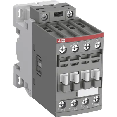
1SBL291201R3400 ABB: The AFC38-40-00-34 is a 4-pole (4 N.O) - 690 V IEC or 600 V UL contactor withScrew terminals, mainly controlling power circuits up to 55 A (IEC AC-1) or 55 A UL general use. Within the AF platform, AFC contactors offer an optimized operating time for AC controlled applications with electromagnetic coil (control voltage : 175 V AC 50 Hz / 208 V AC 60 Hz). AFC contactors have a block type design and can be easily extended with add-on auxiliary contact blocks and a wide range of additionnal accessories.
Minimum Order Quantity
1 piece
Customs Tariff Number
85364900
Data Sheet, Technical Information
1SBC100219C0201 AFC contactors for AC control applications_Catalog PDF
Instructions and Manuals
Installation instructions AF(C)09...38(Z)(B) Contactors, NF(C)(Z)(B)22...80E Contactor relays and CA4, CAL4, CAT4, CC4, LDC4 Accessories
Instructions and Manuals (Part 2)
Contactors and Overload relays guide
Product Net Width
45 mm
Product Net Depth / Length
101 mm
Product Net Height
86 mm
Product Net Weight
0.393 kg
Number of Main Contacts NO
4
Number of Main Contacts NC
0
Number of Auxiliary Contacts NO
0
Number of Auxiliary Contacts NC
0
Number of Poles
4P
Standards
IEC/EN 60947-1, IEC/EN 60947-4-1, UL 60947-1, UL 60947-4-1, CAN/CSA C22.2 No.60947-1, CAN/CSA C22.2 No.60947-4-1
Rated Operational Voltage
Main Circuit 690 V
Rated Frequency (f)
Auxiliary Circuit 50 / 60 Hz | Main Circuit 50 / 60 Hz
Conventional Free-air Thermal Current (Ith)
acc. to IEC 60947-4-1, Open Contactors Θ = 40 °C 55 A
Rated Operational Current AC-1 (Ie)
(690 V) 40 °C 55 A | (690 V) 60 °C 45 A | (690 V) 70 °C 37 A
Rated Operational Current AC-3 (Ie)
(415 V) 60 °C 21.2 A | (440 V) 60 °C 20 A | (500 V) 60 °C 17.6 A | (690 V) 60 °C 10.5 A | (380 / 400 V) 60 °C 22 A | (220 / 230 / 240 V) 60 °C 23.2 A
Rated Operational Power AC-3 (Pe)
(400 V) 11 kW | (415 V) 11 kW | (440 V) 11 kW | (500 V) 11 kW | (690 V) 9 kW | (220 / 230 / 240 V) 5.5 kW
Rated Short-time Withstand Current Low Voltage (Icw)
at 40 °C Ambient Temp, in Free Air, from a Cold State 10 s 300 A | at 40 °C Ambient Temp, in Free Air, from a Cold State 15 min 55 A | at 40 °C Ambient Temp, in Free Air, from a Cold State 1 min 150 A | at 40 °C Ambient Temp, in Free Air, from a Cold State 1 s 450 A | at 40 °C Ambient Temp, in Free Air, from a Cold State 30 s 225 A
Rated Insulation Voltage (Ui)
acc. to IEC 60947-4-1 and VDE 0110 (Gr. C) 690 V | acc. to UL/CSA 600 V
Maximum Electrical Switching Frequency
(AC-1) 600 cycles per hour
Maximum Mechanical Switching Frequency
3600 cycles per hour
Rated Control Circuit Voltage (Uc)
50 Hz 175 V | 60 Hz 208 V
Coil Consumption
Average Holding Value 50 / 60 Hz 8 V·A | Average Pull-in Value 50 Hz 70 V·A | Average Pull-in Value 60 Hz 66 V·A
Power Loss
at Rated Operating Conditions AC-1 per Pole 2.3 W | at Rated Operating Conditions AC-3 per Pole 0.42 W
Operate Time
Between Coil De-energization and NC Contact Closing 9 ... 20 ms | Between Coil De-energization and NO Contact Opening 4 ... 18 ms | Between Coil Energization and NC Contact Opening 7 ... 21 ms | Between Coil Energization and NO Contact Closing 10 ... 26 ms
Mounting on DIN Rail
TH35-15 (35 x 15 mm Mounting Rail) acc. to IEC 60715 | TH35-7.5 (35 x 7.5 mm Mounting Rail) acc. to IEC 60715
Mounting by Screws (not supplied)
2 x M4 screws placed diagonally
Connecting Capacity Main Circuit
Flexible with Ferrule 1/2x 1.5 ... 16 mm² | Flexible with Insulated Ferrule 1/2x 1.5 ... 16 mm² | Flexible with Insulated Ferrule 1x 1.5 ... 16 mm² | Flexible with Insulated Ferrule 2x 1.5 ... 16 mm² | Rigid 1/2x 1.5 ... 16 mm²
Connecting Capacity Control Circuit
Flexible with Ferrule 1/2x 0.75 ... 2.5 mm² | Flexible with Insulated Ferrule 1x 0.75 ... 2.5 mm² | Flexible with Insulated Ferrule 2x 0.75 ... 1.5 mm² | Rigid 1/2x 1 ... 2.5 mm²
Wire Stripping Length
Control Circuit 10 mm | Main Circuit 12 mm
Degree of Protection
acc. to IEC 60529, IEC 60947-1, EN 60529 Coil Terminals IP20 | acc. to IEC 60529, IEC 60947-1, EN 60529 Main Terminals IP20
Tightening Torque
Control Circuit 1.2 N·m | Main Circuit 2.5 N·m
Terminal Type
Screw Terminals
Product Name
Block Contactor
Maximum Operating Voltage UL/CSA
Main Circuit 600 V
General Use Rating UL/CSA
(600 V AC) 55 A
Tightening Torque UL/CSA
Control Circuit 11 in·lb | Main Circuit 22 in·lb
Ambient Air Temperature
Close to Contactor for Storage -60 ... +80 °C | Near Contactor for Operation in Free Air -40 ... 70 °C | Near Contactor for Operation in Free Air (0.85 ... 1.1 Uc) -40 ... +60 °C | Near Contactor for Operation in Free Air (Uc) -40 ... 70 °C
Climatic Withstand
Category B according to IEC 60947-1 Annex Q
Maximum Operating Altitude Permissible
Without Derating 3000 m
Resistance to Shock acc. to IEC 60068-2-27
Closed, Shock Direction: B1 25 g | Open, Shock Direction: B1 5 g | Shock Direction: A 30 g | Shock Direction: B2 15 g | Shock Direction: C1 25 g | Shock Direction: C2 25 g
Resistance to Vibrations
4g Closed Position & 2g Open position 5 ... 300 Hz
Pollution Degree
3
REACH Declaration
REACH - Letter of Confirmation for block contactors, contactor relays, installation contactors, mini contactors, mini contactor relays, thermal overload relays, electronic overload relays and related accessories
RoHS Information
RoHS II declaration for block contactors, installation contactors, mini contactors, mini contactor relays, thermal overload relays, electronic overload relays and related accessories
RoHS Status
Following EU Directive 2011/65/EU and Amendment 2015/863 July 22, 2019
Toxic Substances Control Act - TSCA
Toxic Substances Control Act (TSCA) declaration for Contactors
WEEE B2C / B2B
Business To Business
WEEE Category
5. Small Equipment (No External Dimension More Than 50 cm)
BV Certificate
BV Certificate AF(C)09...AF(C)38 3-pole and 4-pole contactors with screw and Push-in Spring terminals
CB Certificate
CB Certificate AF(C)26, AF(C)38, AF26(Z)B, AF38(Z)B 4-pole contactors
Declaration of Conformity - CCC
CCC Declaration of Conformity, Contactor, AF26, AF30, AF38, AFS26, AFS30, AFS38 Made in France
Declaration of Conformity - CE
EU Declaration of Conformity AFC09 ... AFC80 4-pole Contactors
Declaration of Conformity - UKCA
UK Declaration of Conformity AFC09 ... AFC80 4-pole Contactors
DNV Certificate
DNV Certificate AFC09...96 3-pole & AFC09...80 4-pole contactors with screw, push-in terminals
RINA Certificate
Rina Certificate for AFC09...AFC96 3 pole and 4 pole contactors, NFC relays ,screw and spring terminals
UL Certificate
UL-US Certificate of Compliance AFC09 ... AFC38 4-pole contactors | UL-CA Certificate of Compliance AFC09 ... AFC38 4-pole contactors
Package Level 1 Units
box 1 piece
Package Level 1 Width
87 mm
Package Level 1 Depth / Length
103 mm
Package Level 1 Height
47 mm
Package Level 1 Gross Weight
0.418 kg
Package Level 1 EAN
3471523024328
Object Classification Code
Q
ETIM 7
EC000066 - Power contactor, AC switching
ETIM 8
EC000066 - Power contactor, AC switching
ETIM 9
EC000066 - Power contactor, AC switching
eClass
V11.0 : 27371003
UNSPSC
39121529
IDEA Granular Category Code (IGCC)
4755 >> Contactors
Feature → Business Impact → Application: The 4 NO main contacts and 4-pole design simplify wiring and reduce interconnections, delivering higher fault tolerance and streamlined panel layouts for demanding motors and pumps. This improves reliability and speeds commissioning in automation lines. Feature → Business Impact → Application: Coil options of 175 V AC 50 Hz / 208 V AC 60 Hz enable seamless integration with common control circuits, lowering engineering time and reducing mis‑selection risk in mixed voltage environments. Feature → Business Impact → Application: Rated main circuit voltage at 690 V and AC-1 current up to 55 A with AC-3 values around 21–23 A at typical voltages support efficient, standards-compliant motor start/stop cycles in conveyors and processing lines. Feature → Business Impact → Application: DIN rail TH35 mounting (TH35-15 or TH35-7.5) plus screw terminal connections simplify installation, maintenance, and future expansion in compact control cabinets. Feature → Business Impact → Application: IP20 protection and a wide operating temperature range deliver reliability in factory floors with dust, vibrations, and temperature fluctuations, reducing unexpected downtime. Feature → Business Impact → Application: Compliance with IEC/EN 60947-1, IEC/EN 60947-4-1, UL/CSA and related certifications removes regulatory bottlenecks for global deployments, while allowing easy integration with add-on accessories like auxiliary contact blocks for expanded monitoring and control.
Get a Quick Quote for a ABB 1SBL291201R3400
Chat with us on WhatsApp - fast responses guaranteed
Need to speak with someone? We'll call you back within 2 hours during business hours
Interested in ABB 1SBL291201R3400?
Enquire Now
FAQs
The contactor supports DIN rail mounting on TH35 profiles (TH35-15 or TH35-7.5) and can also be secured via two diagonal M4 screws. This provides flexible integration in compact control panels and easy retrofits in existing installations.
Main circuit rated voltage is 690 V with AC-1 current up to 55 A and AC-3 current approx. 21.2–23.2 A depending on voltage. Power rating for AC-3 is about 11 kW at common motor voltages, Ui is 690 V, and the coil operates at 175 V AC (50 Hz) / 208 V AC (60 Hz).
Yes. With four NO main contacts and appropriate short-time withstand capability, the device is well-suited for motor start/stop sequences in conveyors, pumps, and processing equipment. When used with auxiliary contact blocks, you can monitor status and integrate into PLC feedback loops for safer, more reliable operation.
The product carries CE and UL/CSA approvals, along with CB and BV certifications. It also aligns with IEC/EN 60947-1 and 60947-4-1 standards, with additional regulatory marks like UKCA and CCC documented, ensuring global compatibility and formal conformity across multiple markets.
Ensure coil voltage matches your control circuit (175 V / 208 V options), use screw terminals or ferrules within listed cross-sections to prevent loose connections, and leverage add-on auxiliary blocks for diagnostics. The coil consumption is 8 V·A holding and higher pull-in values, with 2.3 W power loss per pole, translating to predictable running costs and reduced downtime.