ABB 1SBL297001R1211 Block Contactor - 690V AC-3
Part Number: 1SBL297001R1211
Quick Summary
Block Contactor ABB 1SBL297001R1211 delivers reliable motor control for industrial machinery in manufacturing, packaging, and process lines. Operators often face voltage fluctuations and panel energy waste that disrupt start-up sequences and shorten motor life. Manufacturers rely on IEC/EN 60947-1, IEC/EN 60947-4-1 and UL 60335-2-40 certifications to ensure safety and performance across global sites. With AF technology offering a wide control voltage range of 48-130 V and built-in surge protection, you can reduce wiring complexity and improve energy efficiency. This model is compact (45 mm wide) and compatible with add-on auxiliary contacts to tailor control circuits, simplifying panel design and spare-parts management.
Product Information
Extended Description
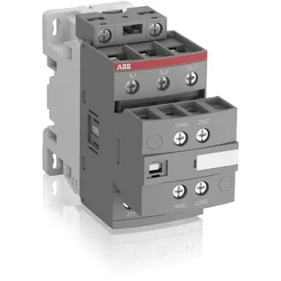
1SBL297001R1211 ABB: The AF38-30-11-12 is a 3 pole - 690 V IEC or 600 UL contactor with pre-mounted auxiliary contacts and screw terminals, controlling motors up to 18.5 kW / 400 V AC (AC-3) or 25 hp / 480 V UL and switching power circuits up to 50 A (AC-1) or 50 A UL general use. Thanks to the AF technology, the contactor has a wide control voltage range (48-130 V 50/60 Hz and DC), managing large control voltage variations, reducing panel energy consumptions and ensuring distinct operations in unstable networks. Furthermore, surge protection is built-in, offering a compact solution. AF contactors have a block type design, can be easily extended with add-on auxiliary contact blocks and an additional wide range of accessories.
Minimum Order Quantity
1 piece
Data Sheet, Technical Information
1SBC100214C0202 - Main catalog Motor protection and control Manual motor starters, contactors and overload relays (PDF) - Edition 2024
Instructions and Manuals
Installation instructions AF(C)09...38(Z)(B) Contactors, NF(C)(Z)(B)22...80E Contactor relays and CA4, CAL4, CAT4, CC4, LDC4 Accessories
Instructions and Manuals (Part 2)
Contactors and Overload relays guide
CAD Dimensional Drawing
Information - 2D and 3D files for CAD systems
Product Net Width
45 mm
Product Net Depth / Length
111.5 mm
Product Net Height
86 mm
Product Net Weight
0.35 kg
Number of Main Contacts NO
3
Number of Main Contacts NC
0
Number of Auxiliary Contacts NO
1
Number of Auxiliary Contacts NC
1
Number of Poles
3P
Standards
IEC/EN 60947-1, IEC/EN 60947-4-1, UL 60335-2-40 LZGH2 A2L, UL 60947-4-1, CSA C22.2 No. 60335-2-40 LZGH2 A2L, CSA C22.2 No. 60947-4-1
Rated Operational Voltage
Auxiliary Circuit 690 V | Main Circuit 690 V
Rated Frequency (f)
Auxiliary Circuit 50 / 60 Hz | Control Circuit 50 / 60 Hz | Main Circuit 50 / 60 Hz
Conventional Free-air Thermal Current (Ith)
acc. to IEC 60947-4-1, Open Contactors Θ = 40 °C 50 A | acc. to IEC 60947-5-1, Θ = 40 °C 16 A
Rated Operational Current AC-1 (Ie)
(690 V) 40 °C 50 A | (690 V) 60 °C 42 A | (690 V) 70 °C 37 A
Rated Operational Current AC-3 (Ie)
(415 V) 60 °C 38 A | (440 V) 60 °C 38 A | (500 V) 60 °C 33 A | (690 V) 60 °C 24 A | (380 / 400 V) 60 °C 38 A | (220 / 230 / 240 V) 60 °C 40 A
Rated Operational Current AC-3e (Ie)
(415 V) 60 °C 38 A | (440 V) 60 °C 38 A | (500 V) 60 °C 33 A | (690 V) 60 °C 24 A | (380 / 400 V) 60 °C 38 A | (220 / 230 / 240 V) 60 °C 40 A
Rated Operational Current AC-15 (Ie)
(500 V) 2 A | (690 V) 2 A | (24 / 127 V) 6 A | (220 / 240 V) 4 A | (400 / 440 V) 3 A
Rated Operational Current DC-1 (Ie)
(110 V) 2 Poles in Series, 40 °C 50 A | (110 V) 2 Poles in Series, 60 °C 42 A | (110 V) 2 Poles in Series, 70 °C 37 A | (110 V) 3 Poles in Series, 40 °C 50 A | (110 V) 3 Poles in Series, 60 °C 42 A | (110 V) 3 Poles in Series, 70 °C 37 A | (220 V) 3 Poles in Series, 40 °C 50 A | (220 V) 3 Poles in Series, 60 °C 42 A | (220 V) 3 Poles in Series, 70 °C 37 A | (72 V) 1-Pole, 40 °C 50 A | (72 V) 1-Pole, 60 °C 42 A | (72 V) 1-Pole, 70 °C 37 A | (72 V) 2 Poles in Series, 40 °C 50 A | (72 V) 2 Poles in Series, 60 °C 42 A | (72 V) 2 Poles in Series, 70 °C 37 A | (72 V) 3 Poles in Series, 40 °C 50 A | (72 V) 3 Poles in Series, 60 °C 42 A | (72 V) 3 Poles in Series, 70 °C 37 A
Rated Operational Current DC-3 (Ie)
(110 V) 2 Poles in Series, 40 °C 50 A | (110 V) 2 Poles in Series, 60 °C 42 A | (110 V) 2 Poles in Series, 70 °C 37 A | (110 V) 3 Poles in Series, 40 °C 50 A | (110 V) 3 Poles in Series, 60 °C 42 A | (110 V) 3 Poles in Series, 70 °C 37 A | (220 V) 3 Poles in Series, 40 °C 50 A | (220 V) 3 Poles in Series, 60 °C 42 A | (220 V) 3 Poles in Series, 70 °C 37 A | (72 V) 1-Pole, 40 °C 50 A | (72 V) 1-Pole, 60 °C 42 A | (72 V) 1-Pole, 70 °C 37 A | (72 V) 2 Poles in Series, 40 °C 50 A | (72 V) 2 Poles in Series, 60 °C 42 A | (72 V) 2 Poles in Series, 70 °C 37 A | (72 V) 3 Poles in Series, 40 °C 50 A | (72 V) 3 Poles in Series, 60 °C 42 A | (72 V) 3 Poles in Series, 70 °C 37 A
Rated Operational Current DC-5 (Ie)
(110 V) 2 Poles in Series, 40 °C 50 A | (110 V) 2 Poles in Series, 60 °C 42 A | (110 V) 2 Poles in Series, 70 °C 37 A | (110 V) 3 Poles in Series, 40 °C 50 A | (110 V) 3 Poles in Series, 60 °C 42 A | (110 V) 3 Poles in Series, 70 °C 37 A | (220 V) 3 Poles in Series, 40 °C 25 A | (220 V) 3 Poles in Series, 60 °C 25 A | (220 V) 3 Poles in Series, 70 °C 25 A | (72 V) 1-Pole, 40 °C 25 A | (72 V) 1-Pole, 60 °C 25 A | (72 V) 1-Pole, 70 °C 25 A | (72 V) 2 Poles in Series, 40 °C 50 A | (72 V) 2 Poles in Series, 60 °C 42 A | (72 V) 2 Poles in Series, 70 °C 37 A | (72 V) 3 Poles in Series, 40 °C 50 A | (72 V) 3 Poles in Series, 60 °C 42 A | (72 V) 3 Poles in Series, 70 °C 37 A
Rated Operational Current DC-13 (Ie)
(24 V) 6 A / 144 W | (48 V) 2.8 A / 134 W | (72 V) 1 A / 72 W | (110 V) 1.1 A / 121 W | (125 V) 0.55 A / 69 W | (220 V) 0.27 A / 60 W | (250 V) 0.27 A / 68 W | (400 V) 0.15 A / 60 W | (500 V) 0.13 A / 65 W | (600 V) 0.1 A / 60 W
Rated Operational Power AC-3 (Pe)
(400 V) 18.5 kW | (415 V) 18.5 kW | (440 V) 22 kW | (500 V) 22 kW | (690 V) 22 kW | (380 / 400 V) 18.5 kW | (220 / 230 / 240 V) 11 kW
Rated Operational Power AC-3e (Pe)
(415 V) 18.5 kW | (440 V) 22 kW | (500 V) 22 kW | (690 V) 22 kW | (380 / 400 V) 18.5 kW | (220 / 230 / 240 V) 11 kW
Rated Short-time Withstand Current Low Voltage (Icw)
at 40 °C Ambient Temp, in Free Air, from a Cold State 10 s 350 A | at 40 °C Ambient Temp, in Free Air, from a Cold State 15 min 50 A | at 40 °C Ambient Temp, in Free Air, from a Cold State 1 min 150 A | at 40 °C Ambient Temp, in Free Air, from a Cold State 1 s 700 A | at 40 °C Ambient Temp, in Free Air, from a Cold State 30 s 225 A | for 0.1 s 140 A | for 1 s 100 A
Maximum Breaking Capacity
cos phi=0.45 (cos phi=0.35 for Ie > 100 A) at 440 V 500 A | cos phi=0.45 (cos phi=0.35 for Ie > 100 A) at 690 V 200 A
Rated Insulation Voltage (Ui)
acc. to IEC 60947-4-1 690 V | acc. to IEC 60947-5-1 690 V | acc. to UL/CSA 600 V
Rated Impulse Withstand Voltage (Uimp)
6 kV
Maximum Electrical Switching Frequency
(AC-1) 600 cycles per hour | (AC-15) 1200 cycles per hour | (AC-2 / AC-4) 150 cycles per hour | (AC-3) 1200 cycles per hour | (DC-13) 900 cycles per hour
Maximum Mechanical Switching Frequency
3600 cycles per hour
Rated Control Circuit Voltage (Uc)
50 Hz 48 ... 130 V | 60 Hz 48 ... 130 V | DC Operation 48 ... 130 V
Power Loss
at 6 A per Pole 0.1 W | at Rated Operating Conditions AC-1 per Pole 2.4 W | at Rated Operating Conditions AC-3 per Pole 1.3 W
Operate Time
Between Coil De-energization and NC Contact Closing 13 ... 98 ms | Between Coil De-energization and NO Contact Opening 11 ... 95 ms | Between Coil Energization and NC Contact Opening 38 ... 90 ms | Between Coil Energization and NO Contact Closing 40 ... 95 ms
Mounting on DIN Rail
TH35-15 (35 x 15 mm Mounting Rail) acc. to IEC 60715 | TH35-7.5 (35 x 7.5 mm Mounting Rail) acc. to IEC 60715
Mounting by Screws (not supplied)
2 x M4 screws placed diagonally
Connecting Capacity Main Circuit
Flexible with Ferrule 1/2x 1.5 ... 10 mm² | Flexible with Insulated Ferrule 1x 1.5 ... 10 mm² | Flexible with Insulated Ferrule 2x 1.5 ... 4 mm² | Rigid Solid 1/2x 2.5 ... 4 mm² | Rigid Stranded 1/2x 2.5 ... 10 mm²
Connecting Capacity Auxiliary Circuit
Flexible with Ferrule 1/2x 0.75 ... 2.5 mm² | Flexible with Insulated Ferrule 1x 0.75 ... 2.5 mm² | Flexible with Insulated Ferrule 2x 0.75 ... 1.5 mm² | Rigid Solid 1/2x 1 ... 2.5 mm² | Rigid Stranded 1/2x 1 ... 2.5 mm²
Connecting Capacity Control Circuit
Flexible with Ferrule 1/2x 0.75 ... 2.5 mm² | Flexible with Insulated Ferrule 1x 0.75 ... 2.5 mm² | Flexible with Insulated Ferrule 2x 0.75 ... 1.5 mm² | Rigid Solid 1/2x 1 ... 2.5 mm² | Rigid Stranded 1/2x 1 ... 2.5 mm²
Wire Stripping Length
Auxiliary Circuit 10 mm | Control Circuit 10 mm | Main Circuit 14 mm
Degree of Protection
acc. to IEC 60529, IEC 60947-1, EN 60529 Auxiliary Terminals IP20 | acc. to IEC 60529, IEC 60947-1, EN 60529 Coil Terminals IP20 | acc. to IEC 60529, IEC 60947-1, EN 60529 Main Terminals IP20
Tightening Torque
Auxiliary Circuit 1.2 N·m | Control Circuit 1.2 N·m | Main Circuit 2.5 N·m
Terminal Type
Screw Terminals
Product Name
Block Contactor
Maximum Operating Voltage UL/CSA
Main Circuit 600 V
General Use Rating UL/CSA
(600 V AC) 50 A
Horsepower Rating UL/CSA
(120 V AC) Single Phase 2 hp | (200 ... 208 V AC) Three Phase 10 hp | (220 ... 240 V AC) Three Phase 10 hp | (240 V AC) Single Phase 5 hp | (440 ... 480 V AC) Three Phase 25 hp | (550 ... 600 V AC) Three Phase 30 hp
Connecting Capacity Main Circuit UL/CSA
Rigid Solid 1/2x 14-10 AWG | Rigid Stranded 1/2x 14-8 AWG
Connecting Capacity Auxiliary Circuit UL/CSA
Rigid Solid 1/2x 18-14 AWG | Rigid Stranded 1/2x 18-14 AWG
Connecting Capacity Control Circuit UL/CSA
Rigid Solid 1/2x 18-14 AWG | Rigid Stranded 1/2x 18-14 AWG
Tightening Torque UL/CSA
Auxiliary Circuit 11 in·lb | Control Circuit 11 in·lb | Main Circuit 22 in·lb
Full Load Amps Motor Use
(120 V AC) Single Phase 24 A | (200 ... 208 V AC) Three Phase 32.2 A | (220 ... 240 V AC) Three Phase 28 A | (240 V AC) Single Phase 28 A | (440 ... 480 V AC) Three Phase 34 A | (550 ... 600 V AC) Three Phase 32 A
Ambient Air Temperature
Close to Contactor Fitted with Thermal O/L Relay -25 ... 60 °C | Close to Contactor without Thermal O/L Relay -40 ... 70 °C | Close to Contactor for Storage -60 ... +80 °C
Climatic Withstand
Category B according to IEC 60947-1 Annex Q
Maximum Operating Altitude Permissible
Without Derating 3000 m
Resistance to Shock acc. to IEC 60068-2-27
Closed, Shock Direction: B1 25 g | Open, Shock Direction: B1 5 g | Shock Direction: A 30 g | Shock Direction: B2 15 g | Shock Direction: C1 25 g | Shock Direction: C2 25 g
Resistance to Vibrations
4g Closed Position & 2g Open position 5 ... 300 Hz
Pollution Degree
3
Conflict Minerals Reporting Template (CMRT)
CMRT - Conflict Minerals Reporting Template
REACH Declaration
REACH - Letter of Confirmation for block contactors, contactor relays, installation contactors, mini contactors, mini contactor relays, thermal overload relays, electronic overload relays and related accessories
RoHS Information
RoHS II declaration for block contactors, installation contactors, mini contactors, mini contactor relays, thermal overload relays, electronic overload relays and related accessories
RoHS Status
Following EU Directive 2011/65/EU and Amendment 2015/863 July 22, 2019
Toxic Substances Control Act - TSCA
Toxic Substances Control Act (TSCA) declaration for Contactors
WEEE B2C / B2B
Business To Business
WEEE Category
5. Small Equipment (No External Dimension More Than 50 cm)
End Of Life Disassembling Instructions
End of life instruction AF(S)09/12/16/26/30/38(Z)(B)(K)(RT) Contactors & NF(Z)(B)(K)(RT) Contactors relays
Environmental Product Declaration - EPD
Environmental Product Declaration AF(S)26/30/38(Z)(B) Contactors (FR)
Sustainable Material Content in Packaging (wt. %)
Recycled Cardboard - 86 %
Sustainable Material Content in Product (wt. %)
Recycled Metal - 28 %
A2L Certificate – UL
UL-US A2L LZGH2 Certificate of Compliance AF09 ... AF38 3-pole contactors with screw terminals - UL 60335-2-40 Household and Similar Electrical Appliances - Safety - Part 2-40: Particular Requirements for Electrical Heat Pumps, Air-Conditioners and Dehumidifiers | UL-CA A2L LZGH2 Certificate of Compliance AF09 ... AF38 3-pole contactors with screw terminals - CSA C22.2 No. 60335-2-40 Household and Similar Electrical Appliances - Safety - Part 2-40: Particular Requirements for Electrical Heat Pumps, Air-Conditioners and Dehumidifiers
ABS Certificate
ABS Certificate, AF(S)09 to AF(S)96 contactors, NF contactor relays and CA4, CC4, CAL4, CAT4 auxiliary contact blocks, TEF4 electronic timers
BV Certificate
BV Certificate AF(C)09...AF(C)38 3-pole and 4-pole contactors with screw and Push-in Spring terminals
CB Certificate
CB Certificate AF26(Z)(B), AF30(Z)(B), AF(Z)(B)38 3-pole contactors, AFS26, AFS30, AFS38 safety contactors
CCC Certificate
CCC Certificate AF26, AF30, AF38, AF26(Z)B, AF30(Z)B, AF38(Z)B 3 and 4-pole contactors, AFS26, AFS30, AFS38 safety contactors
CQC Certificate
CQC Certificate, Contactor, AF*26, AF*30, AF*38, Made in France | CQC Certificate, Contactor, AF26,AF30,AF38, Made in China
Declaration of Conformity - CCC
CCC Declaration of Conformity, Contactor, AF26, AF30, AF38, AFS26, AFS30, AFS38 Made in France | CCC Declaration of Conformity, Contactor, AF26, AF30, AF38, Made in China
Declaration of Conformity - CE
EU Declaration of Conformity AF09... AF96-30-.., AF09...38(Z)-30..K 3-pole Contactors
Declaration of Conformity - UKCA
UK Declaration of Conformity AF09... AF96-30-.., AF09...38(Z)-30..K 3-pole Contactors
DNV Certificate
DNV Certificate AF(S)09...96 3-pole & AF09...80 4-pole contactors with screw, spring, push-in terminals
GOST Certificate
GOST_POCCFR.ME77.B07175.pdf
KC Certificate
KC Certificate AF26...AF38 3-pole contactors
LR Certificate
LRS Certificate AF(S)09..(K) ... AF96 3 and 4-pole contactors and CA(L)4..(K), CAT4, CC4 auxiliary contact blocks
RINA Certificate
Rina Certificate for AF(S)09...AF(S)96 contactors, NF contactor relays and accessories with screw,spring and push-in terminals
RMRS Certificate
RMRS Certificate AF(S)09(S)...AF(S)38 3-pole and 4-pole, AF(S)40..96 3-pole contactors with screw, push-in and spring terminals
UL Certificate
UL-US Certificate of Compliance AF(C)(S)09(R/M/N)-..(L)(S)(K)...AF(C)(S)38(R/M/N)..(K) 3-pole contactors screw, spring and push-in spring terminals; LDC4 additional coil terminal block; LF16-4, LG16-4, LF38-4 and LH38-4 connecting strips, LD38-4 additional terminal block | UL-CA Certificate of Compliance AF(C)(S)09(R/M/N)-..(L)(S)(K)...AF(C)(S)38(R/M/N)..(K) 3-pole contactors screw, spring and push-in spring terminals; LDC4 additional coil terminal block; LF16-4, LG16-4, LF38-4 and LH38-4 connecting strips, LD38-4 additional terminal block
UL Listing Card
E312527
Package Level 1 Units
box 1 piece
Package Level 1 Width
87 mm
Package Level 1 Depth / Length
114 mm
Package Level 1 Height
47 mm
Package Level 1 Gross Weight
0.35 kg
Package Level 1 EAN
3471523111622
Package Level 2 Units
box 18 piece
Package Level 2 Width
250 mm
Package Level 2 Depth / Length
300 mm
Package Level 2 Height
315 mm
Package Level 2 Gross Weight
12.6 kg
Package Level 3 Units
864 piece
Object Classification Code
Q
ETIM 7
EC000066 - Power contactor, AC switching
ETIM 8
EC000066 - Power contactor, AC switching
ETIM 9
EC000066 - Power contactor, AC switching
eClass
V11.0 : 27371003
UNSPSC
39121529
AF technology provides a wide control voltage range of 48-130 V (50/60 Hz) and DC operation. This reduces panel energy consumption and improves start-up reliability in networks with voltage fluctuations. Ideal for controlling motors up to 18.5 kW at 400–690 V AC-3. The 3-pole block contactor includes pre-mounted auxiliary contacts (NO/NC), simplifying wiring and enabling easy expansion with add-on auxiliary blocks. This speeds up panel customization for machine tools and process lines. Built-in surge protection minimizes nuisance trips and protects control circuits, reducing downtime and service costs in transient-prone networks. Compact block design with DIN rail mounting TH35-15 and screw terminals supports fast installation, reduced panel depth, and straightforward serviceability in new builds or upgrades. Compliance and protection are ensured through adherence to IEC/EN 60947-1, IEC/EN 60947-4-1, UL 60335-2-40, and CSA standards, helping global machines meet regulatory requirements without custom engineering. Electrical ratings provide clarity for design decisions: main circuit rated up to 690 V, AC-3 currents suitable for common motor loads, and auxiliary/control circuits designed for robust panel integration. The device’s compact footprint (45 mm wide, 111.5 mm deep, 86 mm high) and IP20 terminations support predictable installation and reliable field service.
Get a Quick Quote for a ABB 1SBL297001R1211
Chat with us on WhatsApp - fast responses guaranteed
Need to speak with someone? We'll call you back within 2 hours during business hours
Interested in ABB 1SBL297001R1211?
Enquire Now
FAQs
The device supports DIN rail mounting on TH35-15 or TH35-7.5 rails and uses screw terminals for both main and auxiliary circuits. It features 3 main NO contacts with 1 NO and 1 NC auxiliary contact, and requires 2 x M4 screws for panel mounting. Connecting capacity supports flexible ferrule or solid wires within the listed ranges, with wire stripping of 14 mm on the main circuit and 10 mm on auxiliary/control circuits.
For AC-3 operation at 690 V, the contactor is rated up to 24 A (60 °C) and up to 38 A for certain configurations at lower voltages, with power ratings around 18.5 kW at 400–690 V depending on the exact line voltage. For AC-1, rated currents reach up to 50 A, enabling dependable switching of resistive and slightly inductive loads in standard industrial mains.
Yes. It conforms to IEC/EN 60947-1 and 60947-4-1, UL 60335-2-40, CSA listings, and offers CE/UKCA declarations. These certifications support use in multinational facilities and help satisfy regulatory requirements for electrical protection and motor control equipment across diverse markets.
AF technology delivers a wide control voltage range of 48-130 V (50/60 Hz and DC), which tolerates large variations in control signals. This reduces nuisance trips, improves start-up reliability, and lowers panel energy consumption by stabilizing coil operation in unstable networks, ultimately contributing to longer motor life and lower operating costs.
The contactor has a compact footprint: 45 mm width, 111.5 mm depth, and 86 mm height, with a net weight of 0.35 kg. It is designed for DIN-rail mounting (TH35-15 or TH35-7.5) and uses screw terminals for all circuits, with IP20 protection on the terminals. This supports efficient space planning and straightforward service in panel builds.