ABB AF38B-30-00K-14 Block Contactor - 690 V IEC/UL
Part Number: 1SBL297063R1400
Quick Summary
AF38B-30-00K-14 Block Contactor from ABB controls motors in industrial automation applications. In environments with variable control voltages, unstable operation can cause nuisance trips and energy waste. The device complies with IEC/EN 60947-1 and IEC 60947-4-1, UL 60947-4-1, and UL/CSA safety standards, with CE and UKCA declarations for global deployment. Its AF technology offers a wide control voltage range of 250–500 V, integrated surge protection, and a compact block design that supports easy expansion with auxiliary contact blocks. This makes it a robust choice for reliable motor control, reduced panel heat, and straightforward installation in DIN-rail enclosures, delivering cost efficiency through energy savings and predictable performance.
Product Information
Extended Description
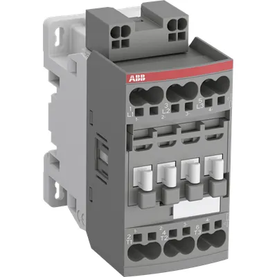
1SBL297063R1400 ABB: The AF38B-30-00K-14 is a 3 pole - 690 V IEC or 600 UL contactor with push-in spring terminals, controlling motors up to 18.5 kW / 400 V AC (AC-3) or 25 hp / 480 V UL and switching power circuits up to 45 A (AC-1) or 50 A UL general use. Thanks to the AF technology, the contactor has a wide control voltage range (250-500 V 50/60 Hz and DC), managing large control voltage variations, reducing panel energy consumptions and ensuring distinct operations in unstable networks. Furthermore, surge protection is built-in, offering a compact solution. AF contactors have a block type design, can be easily extended with add-on auxiliary contact blocks and an additional wide range of accessories.
Minimum Order Quantity
1 piece
Customs Tariff Number
85364900
Data Sheet, Technical Information
Motor control and protection for Rolling stock application_PDF
Instructions and Manuals
Installation instructions AF(C)09...38(Z)(B)..K Contactors, NF(C)(Z)(B)..K Contactor relays and CA4..K, CAL4..K, LDC4K Accessories
Instructions and Manuals (Part 2)
Contactors and Overload relays guide
CAD Dimensional Drawing
Information - 2D and 3D files for CAD systems
Product Net Width
45 mm
Product Net Depth / Length
86 mm
Product Net Height
92.3 mm
Product Net Weight
0.33 kg
Number of Main Contacts NO
3
Number of Main Contacts NC
0
Number of Auxiliary Contacts NO
0
Number of Auxiliary Contacts NC
0
Number of Poles
3P
Standards
IEC/EN 60947-1, IEC/EN 60947-4-1, UL 60947-4-1, CSA C22.2 No. 60947-4-1, IEC 60077-1 (applicable parts), IEC 60077-2 (applicable parts), EN 50155 (applicable parts), TR CU 001/2011, IEC 61373, For compliance confirmation on applicable parts based on your application and combination, please consult your ABB sales representatives.
Rated Operational Voltage
Main Circuit 690 V
Rated Frequency (f)
Control Circuit 50 / 60 Hz | Main Circuit 50 / 60 Hz
Conventional Free-air Thermal Current (Ith)
acc. to IEC 60947-4-1, Open Contactors Θ = 40 °C 50 A
Rated Operational Current AC-1 (Ie)
(690 V) 40 °C 50 A | (690 V) 60 °C 42 A | (690 V) 70 °C 37 A
Rated Operational Current AC-3 (Ie)
(415 V) 60 °C 38 A | (440 V) 60 °C 38 A | (500 V) 60 °C 33 A | (690 V) 60 °C 24 A | (380 / 400 V) 60 °C 38 A | (220 / 230 / 240 V) 60 °C 40 A
Rated Operational Current AC-3e (Ie)
(415 V) 60 °C 38 A | (440 V) 60 °C 38 A | (500 V) 60 °C 33 A | (690 V) 60 °C 24 A | (380 / 400 V) 60 °C 38 A | (220 / 230 / 240 V) 60 °C 40 A
Rated Operational Current DC-1 (Ie)
(110 V) 2 Poles in Series, 40 °C 50 A | (110 V) 2 Poles in Series, 60 °C 42 A | (110 V) 2 Poles in Series, 70 °C 37 A | (110 V) 3 Poles in Series, 40 °C 50 A | (110 V) 3 Poles in Series, 60 °C 42 A | (110 V) 3 Poles in Series, 70 °C 37 A | (220 V) 3 Poles in Series, 40 °C 50 A | (220 V) 3 Poles in Series, 60 °C 42 A | (220 V) 3 Poles in Series, 70 °C 37 A | (72 V) 1-Pole, 40 °C 50 A | (72 V) 1-Pole, 60 °C 42 A | (72 V) 1-Pole, 70 °C 37 A | (72 V) 2 Poles in Series, 40 °C 50 A | (72 V) 2 Poles in Series, 60 °C 42 A | (72 V) 2 Poles in Series, 70 °C 37 A | (72 V) 3 Poles in Series, 40 °C 50 A | (72 V) 3 Poles in Series, 60 °C 42 A | (72 V) 3 Poles in Series, 70 °C 37 A
Rated Operational Current DC-3 (Ie)
(110 V) 2 Poles in Series, 40 °C 50 A | (110 V) 2 Poles in Series, 60 °C 42 A | (110 V) 2 Poles in Series, 70 °C 37 A | (110 V) 3 Poles in Series, 40 °C 50 A | (110 V) 3 Poles in Series, 60 °C 42 A | (110 V) 3 Poles in Series, 70 °C 37 A | (220 V) 3 Poles in Series, 40 °C 50 A | (220 V) 3 Poles in Series, 60 °C 42 A | (220 V) 3 Poles in Series, 70 °C 37 A | (72 V) 1-Pole, 40 °C 50 A | (72 V) 1-Pole, 60 °C 42 A | (72 V) 1-Pole, 70 °C 37 A | (72 V) 2 Poles in Series, 40 °C 50 A | (72 V) 2 Poles in Series, 60 °C 42 A | (72 V) 2 Poles in Series, 70 °C 37 A | (72 V) 3 Poles in Series, 40 °C 50 A | (72 V) 3 Poles in Series, 60 °C 42 A | (72 V) 3 Poles in Series, 70 °C 37 A
Rated Operational Current DC-5 (Ie)
(110 V) 2 Poles in Series, 40 °C 50 A | (110 V) 2 Poles in Series, 60 °C 42 A | (110 V) 2 Poles in Series, 70 °C 37 A | (110 V) 3 Poles in Series, 40 °C 50 A | (110 V) 3 Poles in Series, 60 °C 42 A | (110 V) 3 Poles in Series, 70 °C 37 A | (220 V) 3 Poles in Series, 40 °C 25 A | (220 V) 3 Poles in Series, 60 °C 25 A | (220 V) 3 Poles in Series, 70 °C 25 A | (72 V) 1-Pole, 40 °C 25 A | (72 V) 1-Pole, 60 °C 25 A | (72 V) 1-Pole, 70 °C 25 A | (72 V) 2 Poles in Series, 40 °C 50 A | (72 V) 2 Poles in Series, 60 °C 42 A | (72 V) 2 Poles in Series, 70 °C 37 A | (72 V) 3 Poles in Series, 40 °C 50 A | (72 V) 3 Poles in Series, 60 °C 42 A | (72 V) 3 Poles in Series, 70 °C 37 A
Rated Operational Power AC-3 (Pe)
(415 V) 18.5 kW | (440 V) 22 kW | (500 V) 22 kW | (690 V) 22 kW | (380 / 400 V) 18.5 kW | (220 / 230 / 240 V) 11 kW
Rated Operational Power AC-3e (Pe)
(415 V) 18.5 kW | (440 V) 22 kW | (500 V) 22 kW | (690 V) 22 kW | (380 / 400 V) 18.5 kW | (220 / 230 / 240 V) 11 kW
Rated Short-time Withstand Current Low Voltage (Icw)
at 40 °C Ambient Temp, in Free Air, from a Cold State 10 s 350 A | at 40 °C Ambient Temp, in Free Air, from a Cold State 15 min 50 A | at 40 °C Ambient Temp, in Free Air, from a Cold State 1 min 150 A | at 40 °C Ambient Temp, in Free Air, from a Cold State 1 s 700 A | at 40 °C Ambient Temp, in Free Air, from a Cold State 30 s 225 A
Maximum Breaking Capacity
cos phi=0.45 (cos phi=0.35 for Ie > 100 A) at 440 V 500 A | cos phi=0.45 (cos phi=0.35 for Ie > 100 A) at 690 V 200 A
Rated Insulation Voltage (Ui)
acc. to IEC 60947-4-1 690 V | acc. to UL/CSA 600 V
Rated Impulse Withstand Voltage (Uimp)
6 kV
Maximum Electrical Switching Frequency
(AC-1) 600 cycles per hour | (AC-15) 0 cycles per hour | (AC-2 / AC-4) 150 cycles per hour | (AC-3) 1200 cycles per hour | (DC-13) 0 cycles per hour
Maximum Mechanical Switching Frequency
3600 cycles per hour
Rated Control Circuit Voltage (Uc)
50 Hz 250 ... 500 V | 60 Hz 250 ... 500 V | DC Operation 250 ... 500 V
Power Loss
at Rated Operating Conditions AC-1 per Pole 2.44 W | at Rated Operating Conditions AC-3 per Pole 1.41 W
Operate Time
Between Coil De-energization and NC Contact Closing 13 ... 98 ms | Between Coil De-energization and NO Contact Opening 11 ... 95 ms | Between Coil Energization and NC Contact Opening 38 ... 90 ms | Between Coil Energization and NO Contact Closing 40 ... 95 ms
Mounting on DIN Rail
TH35-15 (35 x 15 mm Mounting Rail) acc. to IEC 60715 | TH35-7.5 (35 x 7.5 mm Mounting Rail) acc. to IEC 60715
Mounting by Screws (not supplied)
2 x M4 screws placed diagonally
Connecting Capacity Main Circuit
Flexible with Ferrule 1/2x 1 ... 6 mm² | Flexible with Insulated Ferrule 1/2x 1 ... 6 mm² | Flexible 1/2x 1 ... 6 mm² | Rigid Solid 1/2x 1 ... 2.5 mm² | Rigid Stranded 1/2x 4 ... 10 mm²
Connecting Capacity Control Circuit
Flexible with Ferrule 1/2x 0.5 ... 2.5 mm² | Flexible with Insulated Ferrule 1/2x 0.5 ... 1.5 mm² | Flexible 1/2x 0.5 ... 2.5 mm² | Rigid 1/2x 1 ... 2.5 mm² | Rigid Solid 1/2x 1 ... 2.5 mm²
Wire Stripping Length
Auxiliary Circuit 0 mm | Control Circuit 10 mm | Main Circuit 14 mm
Degree of Protection
acc. to IEC 60529, IEC 60947-1, EN 60529 Coil Terminals IP20 | acc. to IEC 60529, IEC 60947-1, EN 60529 Main Terminals IP20
Terminal Type
Push-in Spring Terminals
Product Name
Block Contactor
Maximum Operating Voltage UL/CSA
Main Circuit 600 V
General Use Rating UL/CSA
(600 V AC) 45 A
Horsepower Rating UL/CSA
(120 V AC) Single Phase 2 hp | (200 ... 208 V AC) Three Phase 10 hp | (220 ... 240 V AC) Three Phase 10 hp | (240 V AC) Single Phase 5 hp | (440 ... 480 V AC) Three Phase 25 hp | (550 ... 600 V AC) Three Phase 30 hp
Connecting Capacity Main Circuit UL/CSA
Rigid Solid 1/2x 18-14 AWG | Rigid Stranded 1/2x 18-8 AWG
Connecting Capacity Control Circuit UL/CSA
Rigid Solid 1/2x 18-14 AWG
Full Load Amps Motor Use
(120 V AC) Single Phase 24 A | (200 ... 208 V AC) Three Phase 32.2 A | (220 ... 240 V AC) Three Phase 28 A | (240 V AC) Single Phase 28 A | (440 ... 480 V AC) Three Phase 34 A | (550 ... 600 V AC) Three Phase 32 A
Ambient Air Temperature
Close to Contactor without Thermal O/L Relay -40 ... 70 °C | Close to Contactor for Storage -60 ... +80 °C
Climatic Withstand
Category B according to IEC 60947-1 Annex Q
Maximum Operating Altitude Permissible
Without Derating 3000 m
Resistance to Vibrations
4g Closed Position & 2g Open position 5 ... 300 Hz
Shock and Vibration Withstand acc. to IEC 61373
Category 1, Class B
Pollution Degree
3
Conflict Minerals Reporting Template (CMRT)
CMRT - Conflict Minerals Reporting Template
REACH Declaration
REACH - Letter of Confirmation for block contactors, contactor relays, installation contactors, mini contactors, mini contactor relays, thermal overload relays, electronic overload relays and related accessories
RoHS Information
RoHS II declaration for block contactors, installation contactors, mini contactors, mini contactor relays, thermal overload relays, electronic overload relays and related accessories
RoHS Status
Following EU Directive 2011/65/EU and Amendment 2015/863 July 22, 2019
Toxic Substances Control Act - TSCA
Toxic Substances Control Act (TSCA) declaration for Contactors
WEEE B2C / B2B
Business To Business
WEEE Category
5. Small Equipment (No External Dimension More Than 50 cm)
End Of Life Disassembling Instructions
End of life instruction AF(S)09/12/16/26/30/38(Z)(B)(K)(RT) Contactors & NF(Z)(B)(K)(RT) Contactors relays
Environmental Product Declaration - EPD
Environmental Product Declaration AF(S)26/30/38(Z)(B) Contactors (FR)
Sustainable Material Content in Packaging (wt. %)
Recycled Cardboard - 86 %
Sustainable Material Content in Product (wt. %)
Recycled Metal - 28 %
CB Certificate
CB Certificate AF26(Z)(B), AF30(Z)(B), AF(Z)(B)38 3-pole contactors, AFS26, AFS30, AFS38 safety contactors
CCC Certificate
CCC Certificate AF26, AF30, AF38, AF26(Z)B, AF30(Z)B, AF38(Z)B 3 and 4-pole contactors, AFS26, AFS30, AFS38 safety contactors
CQC Certificate
CQC Certificate, Contactor, AF*26, AF*30, AF*38, Made in France
Declaration of Conformity - CCC
CCC Declaration of Conformity, Contactor, AF26, AF30, AF38, AFS26, AFS30, AFS38 Made in France
Declaration of Conformity - CE
EU Declaration of Conformity AF09 ... AF38(Z)B..(K), AF40B ... AF96B 3 and 4-pole contactors
Declaration of Conformity - UKCA
UK Declaration of Conformity AF09 ... AF38(Z)B..(K), AF40B ... AF96B 3 and 4-pole contactors
UL Certificate
UL-US Certificate of Compliance AF(C)(S)09(R/M/N)-..(L)(S)(K)...AF(C)(S)38(R/M/N)..(K) 3-pole contactors screw, spring and push-in spring terminals; LDC4 additional coil terminal block; LF16-4, LG16-4, LF38-4 and LH38-4 connecting strips, LD38-4 additional terminal block | UL-CA Certificate of Compliance AF(C)(S)09(R/M/N)-..(L)(S)(K)...AF(C)(S)38(R/M/N)..(K) 3-pole contactors screw, spring and push-in spring terminals; LDC4 additional coil terminal block; LF16-4, LG16-4, LF38-4 and LH38-4 connecting strips, LD38-4 additional terminal block
Package Level 1 Units
box 1 piece
Package Level 1 Width
93 mm
Package Level 1 Depth / Length
86 mm
Package Level 1 Height
45 mm
Package Level 1 Gross Weight
0.37 kg
Package Level 1 EAN
3471523010543
Package Level 3 Units
1080 piece
Object Classification Code
Q
ETIM 7
EC000066 - Power contactor, AC switching
ETIM 8
EC000066 - Power contactor, AC switching
ETIM 9
EC000066 - Power contactor, AC switching
eClass
V11.0 : 27371003
UNSPSC
39121529
Feature → AF technology delivers a wide control voltage range (250–500 V) and built-in surge protection, enabling stable operation in networks with voltage fluctuations. Business Impact → Reduces panel energy consumption and nuisance trips, improving machine uptime in automation lines. Application → Ideal for conveyors and fans in manufacturing lines where supply quality varies. Feature → 3P, 690 V main circuit with push-in spring terminals and compact 45x86x92.3 mm footprint. Business Impact → Simplifies panel layout, speeds installation, and reduces cabinet size. Application → Suitable for space-constrained control panels in industrial facilities. Feature → DIN-rail mounting (TH35-15 or TH35-7.5) and easy add-on contact blocks compatibility. Business Impact → Lower installation time and scalable control with modular accessories. Application → Clean, serviceable configurations in modern electrical cabinets. Feature → Rated AC-3 power handling up to 24 A at 690 V and AC-1 up to 50 A, with high breaking capacity and low heat generation. Business Impact → Higher motor starting reliability with lower TCO. Application → Suitable for mainstream motor loads in packaging, material handling, and process equipment. Feature → Flexible conductor connections (1/2 x 1–6 mm² main, 0.5–2.5 mm² control) and defined wire stripping lengths. Business Impact → Faster, consistent terminations and reduced installer errors. Application → Industrial wiring scenarios requiring robust, repeatable terminations. Feature → Broad environmental tolerance (−40 to 70 °C, IP20, 3 pollution degree) and wide legal compliance footprint. Business Impact → Reliable operation in harsh factories and rolling stock applications, with minimized regulatory risk. Application → Rail and factory floors with demanding ambient conditions.
Get a Quick Quote for a ABB 1SBL297063R1400
Chat with us on WhatsApp - fast responses guaranteed
Need to speak with someone? We'll call you back within 2 hours during business hours
Interested in ABB 1SBL297063R1400?
Enquire Now
FAQs
Mount the device on TH35-15 or TH35-7.5 DIN rails and use the push-in spring terminals for both main and control circuits. Main circuit connections accommodate flexible ferrule 1/2x 1–6 mm² and rigid/bare conductors, while control circuit accepts 0.5–2.5 mm². Wire stripping lengths required are 14 mm for main and 10 mm for control, ensuring secure, vibration-resistant terminations in standard control cabinets.
For AC-1 at 690 V, Ie is up to 50 A at 40 °C, 42 A at 60 °C, and 37 A at 70 °C. For AC-3 and AC-3e at 690 V, Ie is 24 A at 60 °C, with other voltage variants (415–500 V, 380–400 V, 220–240 V) offering 38–40 A ranges. These ratings support reliable, widely varied motor starting and running applications with predictable thermal margins.
Yes, the AF38B-30-00K-14 supports demanding environments and is referenced with EN 50155 applicable parts among its standards. It offers robust protection (IP20) and wide ambient temperature tolerance (−40 to 70 °C), making it suitable for rolling stock controls as well as rugged industrial automation panels where voltage variability and vibration are concerns.
The device conforms to IEC/EN 60947-1 and 60947-4-1, UL 60947-4-1, and CSA C22.2 No. 60947-4-1, with CE and UKCA declarations for global deployment. It also aligns with RoHS, REACH, and TSCA requirements, and ABB provides DoCs and EPDS for environmental and safety declarations, supporting regulatory compliance across regions.
AF technology offers a wide control voltage range and integrated surge protection, reducing energy waste and panel heating. The modular design supports easy expansion with auxiliary contact blocks, lowering maintenance costs and downtime. Overall, you gain improved reliability, faster commissioning, and a lower total cost of ownership in automated motor control applications.