ABB 1SBL297561R1400 Block Contactor - IEC/EN 60947-4-1
Part Number: 1SBL297561R1400
Quick Summary
ABB 1SBL297561R1400 Block Contactor is a four-pole motor control device designed for reliable switching of industrial motors in challenging environments. When control voltage varies widely, you risk chatter, energy waste, and unplanned downtime; this unit’s wide control voltage range helps maintain stable operation. It meets IEC/EN 60947-4-1, UL 60335-2-40 LZGH2 A2L, and CSA C22.2 No. 60335-2-40, supporting safe global deployment across manufacturing lines, conveyors, and rolling stock systems. In addition to reliability and protection, the AF technology minimizes energy consumption in panels, while the compact block design simplifies integration. Compatibility with add-on auxiliary blocks and a broad accessory range supports scalable, cost-efficient protection as your application evolves.
Product Information
Extended Description
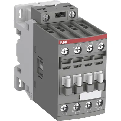
1SBL297561R1400 ABB: The AF38B-22-00-14 is a 4 pole - 690 V IEC or 600 UL contactor with screw terminals, controlling motors up to 11 kW / 400 V AC (AC-3) and switching power circuits up to 55 A (AC-1) or 55 A UL general use. Thanks to the AF technology, the contactor has a wide control voltage range (250-500 V 50/60 Hz and DC), managing large control voltage variations, reducing panel energy consumptions and ensuring distinct operations in unstable networks. Furthermore, surge protection is built-in, offering a compact solution. AF contactors have a block type design, can be easily extended with add-on auxiliary contact blocks and an additional wide range of accessories.
Minimum Order Quantity
1 piece
Customs Tariff Number
85364900
Data Sheet, Technical Information
Motor control and protection for Rolling stock application_PDF
Instructions and Manuals
Installation instructions AF(C)09...38(Z)(B) Contactors, NF(C)(Z)(B)22...80E Contactor relays and CA4, CAL4, CAT4, CC4, LDC4 Accessories
Instructions and Manuals (Part 2)
Contactors and Overload relays guide
CAD Dimensional Drawing
Information - 2D and 3D files for CAD systems
Product Net Width
45 mm
Product Net Depth / Length
101 mm
Product Net Height
86 mm
Product Net Weight
0.41 kg
Number of Main Contacts NO
2
Number of Main Contacts NC
2
Number of Auxiliary Contacts NO
0
Number of Auxiliary Contacts NC
0
Number of Poles
4P
Standards
IEC/EN 60947-1, IEC/EN 60947-4-1, UL 60335-2-40 LZGH2 A2L, UL 60947-1, UL 60947-4-1, CSA C22.2 No. 60335-2-40 LZGH2 A2L, CSA C22.2 No. 60947-1, CSA C22.2 No. 60947-4-1, IEC 60077-1 (applicable parts), IEC 60077-2 (applicable parts), EN 50155 (applicable parts), TR CU 001/2011, IEC 61373, For compliance confirmation on applicable parts based on your application and combination, please consult your ABB sales representatives.
Rated Operational Voltage
Main Circuit 690 V
Rated Frequency (f)
Control Circuit 50 / 60 Hz | Main Circuit 50 / 60 Hz
Conventional Free-air Thermal Current (Ith)
acc. to IEC 60947-4-1, Open Contactors Θ = 40 °C 55 A
Rated Operational Current AC-1 (Ie)
(1000 V) 60 °C 45 A | (690 V) 40 °C 55 A | (690 V) 70 °C 37 A
Rated Operational Current AC-3 (Ie)
(415 V) 60 °C 21.2 A | (440 V) 60 °C 20 A | (500 V) 60 °C 17.6 A | (690 V) 60 °C 10.5 A | (380 / 400 V) 60 °C 22 A | (220 / 230 / 240 V) 60 °C 23.2 A
Rated Operational Power AC-3 (Pe)
(400 V) 11 kW | (415 V) 11 kW | (440 V) 11 kW | (500 V) 11 kW | (690 V) 9 kW | (220 / 230 / 240 V) 5.5 kW
Rated Short-time Withstand Current Low Voltage (Icw)
at 40 °C Ambient Temp, in Free Air, from a Cold State 10 s 300 A | at 40 °C Ambient Temp, in Free Air, from a Cold State 15 min 55 A | at 40 °C Ambient Temp, in Free Air, from a Cold State 1 min 150 A | at 40 °C Ambient Temp, in Free Air, from a Cold State 1 s 450 A | at 40 °C Ambient Temp, in Free Air, from a Cold State 30 s 225 A
Rated Insulation Voltage (Ui)
acc. to IEC 60947-4-1 690 V | acc. to UL/CSA 600 V
Rated Impulse Withstand Voltage (Uimp)
6 kV
Rated Control Circuit Voltage (Uc)
50 Hz 250 ... 500 V | 60 Hz 250 ... 500 V | DC Operation 250 ... 500 V
Power Loss
at Rated Operating Conditions AC-1 per Pole 2.3 W | at Rated Operating Conditions AC-3 per Pole 0.42 W
Mounting on DIN Rail
TH35-15 (35 x 15 mm Mounting Rail) acc. to IEC 60715 | TH35-7.5 (35 x 7.5 mm Mounting Rail) acc. to IEC 60715
Mounting by Screws (not supplied)
2 x M4 screws placed diagonally
Connecting Capacity Main Circuit
Flexible with Ferrule 1/2x 1.5 ... 16 mm² | Flexible with Insulated Ferrule 1/2x 1.5 ... 16 mm² | Rigid Solid 1/2x 1.5 ... 4 mm² | Rigid Stranded 1/2x 1.5 ... 16 mm²
Connecting Capacity Control Circuit
Flexible with Ferrule 1/2x 0.75 ... 2.5 mm² | Flexible with Insulated Ferrule 1x 0.75 ... 2.5 mm² | Flexible with Insulated Ferrule 2x 0.75 ... 1.5 mm² | Rigid Solid 1/2x 1 ... 2.5 mm² | Rigid Stranded 1/2x 1 ... 2.5 mm²
Wire Stripping Length
Control Circuit 10 mm | Main Circuit 12 mm
Degree of Protection
acc. to IEC 60529, IEC 60947-1, EN 60529 Coil Terminals IP20 | acc. to IEC 60529, IEC 60947-1, EN 60529 Main Terminals IP20
Tightening Torque
Control Circuit 1.2 N·m | Main Circuit 2.5 N·m
Terminal Type
Screw Terminals
Product Name
Block Contactor
Maximum Operating Voltage UL/CSA
Main Circuit 600 V
General Use Rating UL/CSA
(600 V AC) 55 A
Connecting Capacity Main Circuit UL/CSA
Rigid Solid 1/2x 16-10 AWG | Rigid Stranded 1/2x 16-6 AWG
Connecting Capacity Control Circuit UL/CSA
Rigid Solid 1/2x 18-14 AWG | Rigid Stranded 1/2x 18-14 AWG
Tightening Torque UL/CSA
Control Circuit 11 in·lb | Main Circuit 22 in·lb
Ambient Air Temperature
Close to Contactor for Storage -60 ... +80 °C | Near Contactor for Operation in Free Air -40 ... 70 °C
Climatic Withstand
Category B according to IEC 60947-1 Annex Q
Maximum Operating Altitude Permissible
Without Derating 3000 m
Shock and Vibration Withstand acc. to IEC 61373
Category 1, Class B
Pollution Degree
3
Conflict Minerals Reporting Template (CMRT)
CMRT - Conflict Minerals Reporting Template
REACH Declaration
REACH - Letter of Confirmation for block contactors, contactor relays, installation contactors, mini contactors, mini contactor relays, thermal overload relays, electronic overload relays and related accessories
RoHS Information
RoHS II declaration for block contactors, installation contactors, mini contactors, mini contactor relays, thermal overload relays, electronic overload relays and related accessories
RoHS Status
Following EU Directive 2011/65/EU and Amendment 2015/863 July 22, 2019
Toxic Substances Control Act - TSCA
Toxic Substances Control Act (TSCA) declaration for Contactors
WEEE B2C / B2B
Business To Business
WEEE Category
5. Small Equipment (No External Dimension More Than 50 cm)
End Of Life Disassembling Instructions
End of life instruction AF(S)09/12/16/26/30/38(Z)(B)(K)(RT) Contactors & NF(Z)(B)(K)(RT) Contactors relays
Environmental Product Declaration - EPD
Environmental Product Declaration AF(S)26/30/38(Z)(B) Contactors (FR)
Sustainable Material Content in Packaging (wt. %)
Recycled Cardboard - 86 %
Sustainable Material Content in Product (wt. %)
Recycled Metal - 28 %
A2L Certificate – UL
UL-US A2L LZGH2 Certificate of Compliance AF09 ... AF38 3-pole contactors with screw terminals - UL 60335-2-40 Household and Similar Electrical Appliances - Safety - Part 2-40: Particular Requirements for Electrical Heat Pumps, Air-Conditioners and Dehumidifiers | UL-CA A2L LZGH2 Certificate of Compliance AF09 ... AF38 3-pole contactors with screw terminals - CSA C22.2 No. 60335-2-40 Household and Similar Electrical Appliances - Safety - Part 2-40: Particular Requirements for Electrical Heat Pumps, Air-Conditioners and Dehumidifiers
CB Certificate
CB Certificate AF26, AF38, AF26(Z)B, AF38(Z)B 4-pole contactors
CCC Certificate
CCC Certificate AF26, AF30, AF38, AF26(Z)B, AF30(Z)B, AF38(Z)B 3 and 4-pole contactors, AFS26, AFS30, AFS38 safety contactors
CQC Certificate
CQC Certificate, Contactor, AF*26, AF*30, AF*38, Made in France
Declaration of Conformity - CCC
CCC Declaration of Conformity, Contactor, AF26, AF30, AF38, AFS26, AFS30, AFS38 Made in France
Declaration of Conformity - CE
EU Declaration of Conformity AF09 ... AF38(Z)B..(K), AF40B ... AF96B 3 and 4-pole contactors
Declaration of Conformity - UKCA
UK Declaration of Conformity AF09 ... AF38(Z)B..(K), AF40B ... AF96B 3 and 4-pole contactors
GOST Certificate
GOST_POCCFR.ME77.B07175.pdf
KC Certificate
KC Certificate AF26...AF38 4-pole contactors
UL Certificate
UL-US Certificate of Compliance AF(C)09..(K) ... AF(C)38 4-pole contactors with screw and push-in spring terminals | UL-CA Certificate of Compliance AF(C)09..(K) ... AF(C)38 4-pole contactors with screw and push-in spring terminals
UL Listing Card
UL_E319322
Package Level 1 Units
box 1 piece
Package Level 1 Width
87 mm
Package Level 1 Depth / Length
103 mm
Package Level 1 Height
47 mm
Package Level 1 Gross Weight
0.41 kg
Package Level 1 EAN
3471523123441
Package Level 2 Units
box 18 piece
Package Level 2 Width
250 mm
Package Level 2 Depth / Length
300 mm
Package Level 2 Height
315 mm
Package Level 2 Gross Weight
14.76 kg
Package Level 3 Units
864 piece
Object Classification Code
Q
ETIM 7
EC000066 - Power contactor, AC switching
ETIM 8
EC000066 - Power contactor, AC switching
ETIM 9
EC000066 - Power contactor, AC switching
eClass
V11.0 : 27371003
UNSPSC
39121529
IDEA Granular Category Code (IGCC)
4758 >> Iec Contactors
AF technology delivers a wide control voltage range of 250–500 V AC/60 Hz and DC, reducing control-signal sensitivity and energy waste while delivering dependable operation across unstable networks. Feature → Business Impact → Application: Wide voltage tolerance translates to fewer panels rewirings and lower energy cost in drives that experience voltage fluctuations in conveyors and pumps; application in rolling stock control and heavy machinery. Feature → Business Impact → Application: Built-in surge protection and 4P block design simplify panel layout and improve uptime, ideal for compact control panels in manufacturing lines and packaging equipment. Feature → Business Impact → Application: Four-pole configuration with 2 NO/2 NC main contacts and screw terminals supports robust motor switching up to 11 kW at 400–690 V, reducing component count and maintenance. Feature → Business Impact → Application: DIN rail mounting (TH35-15/TH35-7.5) and 2x M4 mounting screws speed installation, lowering commissioning time in new lines and spare-part inventories. Feature → Business Impact → Application: Compatibility with add-on auxiliary contact blocks and accessories enables scalable protection and control without replacing the base unit, delivering long-term cost savings. Feature → Business Impact → Application: IP20 protection and defined torque values ensure reliable field installation and consistent electrical connections, reducing rework during maintenance.
Get a Quick Quote for a ABB 1SBL297561R1400
Chat with us on WhatsApp - fast responses guaranteed
Need to speak with someone? We'll call you back within 2 hours during business hours
Interested in ABB 1SBL297561R1400?
Enquire Now
FAQs
Install on TH35-15 or TH35-7.5 DIN rails, using 2 x M4 screws placed diagonally for secure mounting. Ensure coil terminals are properly insulated and tighten main circuit terminals to 2.5 N·m and control circuit to 1.2 N·m. Follow the 12 mm main circuit wire stripping and refer to the 2D/3D CAD drawings for precise spacing.
Main circuit rated up to 690 V with AC-1 current up to 55 A and AC-3 current up to 10.5–23.2 A depending on voltage. Power handling is up to 11 kW (AC-3) at 400–690 V. Control circuit voltage accepts 250–500 V (AC/60 Hz) or DC, with coil terminals IP20.
Yes, it is designed for rolling stock as reflected in the referenced data sheet and multiple certifications (IEC/EN 60947-4-1, UL/CSA listings, and related declarations). For rolling stock, consult the dedicated Motor control and protection for Rolling stock application sheet to confirm compatibility with system requirements.
The device complies with IEC/EN 60947-1 and 60947-4-1, UL 60335-2-40 (LZGH2 A2L), CSA C22.2 No. 60335-2-40 (LZGH2 A2L), and related declarations. Additional certifications include UL/CSA listings, CE/UKCA declarations, KC/CQC/CCC where applicable, and GOST/CB references for global deployment.
AF technology offers a broad control voltage range, reducing panel energy consumption and minimizing trips caused by voltage variation. Built-in surge protection lowers failure risk, while the compact block design and DIN-rail mounting speed installation and reduces panel footprint, contributing to lower maintenance costs and faster ROI on motor-drive projects.