ABB 1SBL301001R8400 Block Contactor - UL/CSA Listed
Part Number: 1SBL301001R8400
Quick Summary
Block Contactor ABB 1SBL301001R8400 provides reliable AC switching for motor control in industrial environments. Engineers often battle downtime and coil-voltage mismatches when scaling lines; this device offers a 110 V control coil for 50/60 Hz operation and a 690 V main circuit to handle demanding loads. It carries IEC/EN 60947-1, IEC/EN 60947-4-1, and UL/CSA certifications, with IP20 control terminal protection and IP10 main terminals, supporting safer maintenance and easier compliance. By combining compact DIN-rail mounting with robust screw terminals, it reduces panel space, simplifies installation, and aligns with common procurement practices, delivering measurable business value through reliability, efficiency, and lifecycle cost reduction.
Product Information
Extended Description
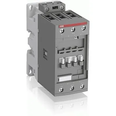
1SBL301001R8400 ABB: AFC78-30-00-84 110V50Hz 110-120V60Hz Contactor
Minimum Order Quantity
1 piece
Customs Tariff Number
85364900
Data Sheet, Technical Information
1SBC100219C0201 AFC contactors for AC control applications_Catalog PDF
Instructions and Manuals
Installation instructions AF(C)40(B)...96(B)-30 Contactors, CA4, CAL4, CAT4, CC4, LDC4 Accessories
Instructions and Manuals (Part 2)
Contactors and Overload relays guide
Product Net Width
55 mm
Product Net Depth / Length
119.5 mm
Product Net Height
111 mm
Product Net Weight
0.98 kg
Number of Main Contacts NO
3
Number of Main Contacts NC
0
Number of Auxiliary Contacts NO
0
Number of Auxiliary Contacts NC
0
Number of Poles
3P
Standards
IEC/EN 60947-1, IEC/EN 60947-4-1, UL 60947-4-1, CSA C22.2 No. 60947-4-1, UL 60335-2-40 LZGH2 A2L
Rated Operational Voltage
Main Circuit 690 V
Rated Frequency (f)
Main Circuit 50 / 60 Hz
Conventional Free-air Thermal Current (Ith)
acc. to IEC 60947-4-1, Open Contactors Θ = 40 °C 105 A | acc. to IEC 60947-5-1, Θ = 40 °C 16 A
Rated Operational Current AC-1 (Ie)
(690 V) 40 °C 105 A | (690 V) 60 °C 90 A | (690 V) 70 °C 80 A
Rated Operational Current AC-3 (Ie)
(415 V) 60 °C 80 A | (440 V) 60 °C 70 A | (380 / 400 V) 60 °C 80 A | (220 / 230 / 240 V) 60 °C 80 A
Rated Operational Current AC-3e (Ie)
(400 V) 60 °C 80 A | (415 V) 60 °C 70 A | (380 / 400 V) 60 °C 80 A | (220 / 230 / 240 V) 60 °C 80 A
Rated Operational Power AC-3 (Pe)
(415 V) 45 kW | (380 / 400 V) 37 kW | (220 / 230 / 240 V) 22 kW
Rated Operational Power AC-3e (Pe)
(415 V) 45 kW | (380 / 400 V) 37 kW | (220 / 230 / 240 V) 22 kW
Rated Short-time Withstand Current Low Voltage (Icw)
at 40 °C Ambient Temp, in Free Air, from a Cold State 15 min 110 A | at 40 °C Ambient Temp, in Free Air, from a Cold State 1 min 250 A | at 40 °C Ambient Temp, in Free Air, from a Cold State 1 s 1000 A | at 40 °C Ambient Temp, in Free Air, from a Cold State 30 s 350 A
Maximum Breaking Capacity
cos phi=0.45 (cos phi=0.35 for Ie > 100 A) at 440 V 950 A | cos phi=0.45 (cos phi=0.35 for Ie > 100 A) at 690 V 600 A
Rated Insulation Voltage (Ui)
acc. to IEC 60947-4-1 and VDE 0110 (Gr. C) 690 V | acc. to UL/CSA 600 V
Rated Impulse Withstand Voltage (Uimp)
Auxiliary Circuit 6 kV
Maximum Electrical Switching Frequency
(AC-1) 600 cycles per hour | (AC-2 / AC-4) 150 cycles per hour | (AC-3) 1200 cycles per hour
Maximum Mechanical Switching Frequency
3600 cycles per hour
Rated Control Circuit Voltage (Uc)
50 Hz 110 V | 50 Hz 110 V | 60 Hz 110 ... 120 V
Coil Consumption
Average Holding Value 50 / 60 Hz 20 V·A | Average Pull-in Value 50 Hz 150 V·A | Average Pull-in Value 60 Hz 151 V·A
Power Loss
at Rated Operating Conditions AC-1 per Pole 7 W | at Rated Operating Conditions AC-3 per Pole 4 W
Operate Time
Between Coil De-energization and NC Contact Closing 6 ... 19 ms | Between Coil De-energization and NO Contact Opening 4 ... 14 ms | Between Coil Energization and NC Contact Opening 3 ... 16 ms | Between Coil Energization and NO Contact Closing 7 ... 21 ms
Mounting on DIN Rail
TH35-15 (35 x 15 mm Mounting Rail) acc. to IEC 60715 | TH35-7.5 (35 x 7.5 mm Mounting Rail) acc. to IEC 60715
Mounting by Screws (not supplied)
2 x M4 or 2 x M6 screws placed diagonally
Connecting Capacity Main Circuit
Flexible with Ferrule 1/2x 4 ... 35 mm² | Flexible with Insulated Ferrule 1/2x 4 ... 35 mm² | Rigid 1/2x 6 ... 3 5 mm² | Rigid 1/2x 6 ... 35 mm²
Connecting Capacity Control Circuit
Flexible with Ferrule 1/2x 0.75 ... 2.5 mm² | Flexible with Insulated Ferrule 1x 0.75 ... 2.5 mm² | Flexible with Insulated Ferrule 2x 0.75 ... 1.5 mm² | Rigid 1/2x 1 ... 2.5 mm²
Wire Stripping Length
Control Circuit 10 mm | Main Circuit 16 mm
Degree of Protection
acc. to IEC 60529, IEC 60947-1, EN 60529 Auxiliary Terminals IP20 | acc. to IEC 60529, IEC 60947-1, EN 60529 Coil Terminals IP20 | acc. to IEC 60529, IEC 60947-1, EN 60529 Main Terminals IP10
Recommended Screw Driver
Main Circuit 6.5 | Main Circuit Slot | Control Circuit 5.5 | Control Circuit Slot
Tightening Torque
Control Circuit 1.2 N·m | Main Circuit 4 N·m
Terminal Type
Screw Terminals
Product Name
Block Contactor
Maximum Operating Voltage UL/CSA
Main Circuit 600 V
General Use Rating UL/CSA
(600 V AC) 90 A
Horsepower Rating UL/CSA
(120 V AC) Single Phase 5 hp | (200 ... 208 V AC) Three Phase 25 hp | (220 ... 240 V AC) Three Phase 30 hp | (240 V AC) Single Phase 7-1/2 hp | (440 ... 480 V AC) Three Phase 60 hp
Tightening Torque UL/CSA
Control Circuit 11 in·lb | Main Circuit 35 in·lb
Full Load Amps Motor Use
(120 V AC) Single Phase 56 A | (200 ... 208 V AC) Three Phase 78.2 A | (220 ... 240 V AC) Three Phase 80 A | (240 V AC) Single Phase 68 A | (440 ... 480 V AC) Three Phase 77 A
Ambient Air Temperature
Close to Contactor without Thermal O/L Relay -40 ... 70 °C | Close to Contactor for Storage -60 ... +80 °C | Near Contactor for Operation in Free Air (0.85 ... 1.1 Uc) -40 ... +60 °C | Near Contactor for Operation in Free Air (Uc) -40 ... 70 °C
Climatic Withstand
Category B according to IEC 60947-1 Annex Q
Maximum Operating Altitude Permissible
Without Derating 3000 m
Resistance to Shock acc. to IEC 60068-2-27
Closed, Shock Direction: A 25 g | Closed, Shock Direction: B1 25 g | Closed, Shock Direction: B2 15 g | Closed, Shock Direction: C1 25 g | Closed, Shock Direction: C2 25 g | Open, Shock Direction: B1 5 g
Pollution Degree
3
REACH Declaration
REACH - Letter of Confirmation for block contactors, contactor relays, installation contactors, mini contactors, mini contactor relays, thermal overload relays, electronic overload relays and related accessories
RoHS Information
RoHS II declaration for block contactors, installation contactors, mini contactors, mini contactor relays, thermal overload relays, electronic overload relays and related accessories
RoHS Status
Following EU Directive 2011/65/EU and Amendment 2015/863 July 22, 2019
Toxic Substances Control Act - TSCA
Toxic Substances Control Act (TSCA) declaration for Contactors
WEEE B2C / B2B
Business To Business
WEEE Category
5. Small Equipment (No External Dimension More Than 50 cm)
A2L Certificate – UL
UL-US Certificate of Compliance AFC40 ... AFC96 3-pole contactors - UL 60335-2-40 Household and Similar Electrical Appliances - Safety - Part 2-40: Particular Requirements for Electrical Heat Pumps, Air-Conditioners and Dehumidifiers | UL-CA Certificate of Compliance AFC40 ... AFC96 3-pole contactors - CSA C22.2 No. 60335-2-40 Household and Similar Electrical Appliances - Safety - Part 2-40: Particular Requirements for Electrical Heat Pumps, Air-Conditioners and Dehumidifiers
BV Certificate
BV_2634H36994B1
CB Certificate
CB Certificate AFC78 3-pole contactors
CCC Certificate
CCC Declaration of Conformity, Contactor, AF(C)40, AF52(C), AF65(C),AFC78 Made in China
Declaration of Conformity - CCC
CCC Declaration of Conformity, Contactor, AF(C)40, AF52(C), AF65(C),AFC78 Made in China
Declaration of Conformity - CE
EU Declaration of Conformity AFC09..(K) ... AFC96 3-pole Contactors
Declaration of Conformity - UKCA
UK Declaration of Conformity AFC09..(K) ... AFC96 3-pole Contactors
DNV Certificate
DNV Certificate AFC09...96 3-pole & AFC09...80 4-pole contactors with screw, push-in terminals
RINA Certificate
Rina Certificate for AFC09...AFC96 3 pole and 4 pole contactors, NFC relays ,screw and spring terminals
UL Certificate
UL-CA Certificate of Compliance AFC40 ... AFC78 3-pole contactors | UL-US Certificate of Compliance AFC40 ... AFC78 3-pole contactors
Package Level 1 Units
box 1 piece
Package Level 1 Width
146.5 mm
Package Level 1 Depth / Length
96.5 mm
Package Level 1 Height
146.5 mm
Package Level 1 Gross Weight
1.1 kg
Package Level 1 EAN
3471523026391
Object Classification Code
Q
ETIM 7
EC000066 - Power contactor, AC switching
ETIM 8
EC000066 - Power contactor, AC switching
ETIM 9
EC000066 - Power contactor, AC switching
eClass
V11.0 : 27371003
UNSPSC
39121529
IDEA Granular Category Code (IGCC)
4755 >> Contactors
Feature: Three-pole main circuit rated to 690 V enables direct control of high-voltage motors. Benefit: Supports demanding AC-1 and AC-3 motor loads while maintaining safe insulation margins, reducing equipment counts and simplifying wiring. Application: Conveyor systems and machine tool lines requiring dependable 690 V switching. Feature: 110 V control coil suitable for 50/60 Hz systems. Benefit: Eliminates the need for multiple coil variants, lowering spare-parts inventory and increasing compatibility with standard plant control circuits. Application: Control cabinets in manufacturing cells with mixed voltage sources. Feature: I_th 105 A (Θ = 40 °C) and Ie AC-3 up to 80 A at 380–415–440 V. Benefit: High inrush tolerance and solid motor-start performance, improving uptime and reducing fuse sizing while meeting end-user load profiles. Application: Pumps, fans, and small to medium conveyors. Feature: Coil consumption 20 V·A holding, ~150–151 V·A pull-in. Benefit: Energy-efficient control with lower standby losses and predictable coil power budgeting. Application: Energy-conscious automation projects and retrofits. Feature: Mechanical and electrical life indicators – 3600 cycles mechanical limit and 6–21 ms operate times. Benefit: Fast, repeatable switching with accurate timing for synchronized motor control and reduced wear on contacts. Application: High-cycle automated lines and packaging equipment. Feature: DIN rail mounting TH35-15 or TH35-7.5 and screw-terminal connections. Benefit: Quick installation, flexible mounting options, and reliable, rugged connections. Application: Panel builders and maintenance shops integrating into standard control enclosures.
Get a Quick Quote for a ABB 1SBL301001R8400
Chat with us on WhatsApp - fast responses guaranteed
Need to speak with someone? We'll call you back within 2 hours during business hours
Interested in ABB 1SBL301001R8400?
Enquire Now
FAQs
Mount the device on a TH35 DIN rail using the TH35-15 or TH35-7.5 options, or secure it with 2 x M4 or M6 screws placed diagonally. For wiring, use main terminals with flexible or rigid conductors 1/2 x 4...35 mm² and control circuit conductors 0.75...2.5 mm². Apply a 4 N·m torque to main terminals and 1.2 N·m to control terminals, with wire-stripping lengths of 16 mm (main) and 10 mm (control). This ensures a reliable, code-compliant installation and easy maintenance.
The device uses a 110 V control coil for both 50 Hz and 60 Hz systems. Coil consumption is 20 V·A in holding, with pull-in power around 150–151 V·A, enabling predictable control current and compact control circuits. This simplifies integration with standard control systems and reduces overall energy use in idle states.
Yes. For AC-1 operation at 690 V, Ie is 105 A at 40 °C, 90 A at 60 °C, and 80 A at 70 °C. For AC-3 at various voltages, Ie ranges up to 80 A (e.g., 415 V, 60 °C) and 70–80 A for 440–380/400 V and 220–240 V ranges. P_e values reflect practical motor drive power, enabling confident selection for pumps, conveyors, and other inductive loads.
The 1SBL301001R8400 complies with IEC/EN 60947-1 and 60947-4-1, and is UL 60947-4-1 listed with CSA; CE and UKCA declarations are provided. This combination supports safe installation across multiple regions, aligns with standard motor-contactor applications, and facilitates regulatory approvals for mixed-country projects.
With a maximum mechanical switching frequency of 3600 cycles per hour and 7 W per pole loss, the device offers durable operation and reduced energy costs. Its compact dimensions (55 mm width, 119.5 mm depth, 111 mm height) and 0.98 kg weight simplify replacements and logistics. The combination of robust protection, reliable coil performance, and standard mounting reduces downtime and total cost of ownership in high-cycle automation environments.