ABB 1SDA097179R1 Moulded Case Circuit Breaker - Tmax T4
Part Number: 1SBL341201R8400
Quick Summary
1SDA097179R1 Moulded Case Circuit Breaker provides reliable motor protection in industrial panels. A common challenge is fitting robust protection into compact electrical cabinets without compromising service. This Tmax T4 device carries CE conformity, RoHS/REACH declarations, and CMRT/TSCA transparency for global compliance. With a 4P design and a 250–1600 A rating, it scales across drives, feeders, and distribution blocks, while installation remains straightforward. Electrical engineers and procurement teams value design consistency with ABB SACE Tmax T families and clear, auditable documentation that speeds audits and approvals. The combination of safety, regulatory readiness, and proven performance translates to reduced downtime and a lower total cost of ownership in demanding manufacturing environments.
Product Information
Extended Description
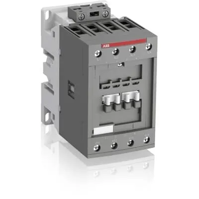
1SBL341201R8400 ABB: The AFC40-40-00-84 is a 4-pole (4 N.O) - 690 V IEC or 600 V UL contactor with Screw terminals, mainly controlling power circuits up to 70 A (IEC AC-1) or 60 A UL general use. Within the AF platform, AFC contactors offer an optimized operating time for AC controlled applications with electromagnetic coil (control voltage : 110 V AC 50 Hz / 110 ... 120 V AC 60 Hz). AFC contactors have a block type design and can be easily extended with add-on auxiliary contact blocks and a wide range of additionnal accessories.
Minimum Order Quantity
1 piece
Customs Tariff Number
85364900
Data Sheet, Technical Information
1SBC100219C0201 AFC contactors for AC control applications_Catalog PDF
Instructions and Manuals
Installation instructions AF(C)40(B)...80(B)-40/22 Contactors, CA4, CAL4, CAT4, CC4, LDC4 Accessories
Instructions and Manuals (Part 2)
Contactors and Overload relays guide
Product Net Width
70 mm
Product Net Depth / Length
119.5 mm
Product Net Height
113.5 mm
Product Net Weight
1.18 kg
Number of Main Contacts NO
4
Number of Main Contacts NC
0
Number of Auxiliary Contacts NO
0
Number of Auxiliary Contacts NC
0
Number of Poles
4P
Standards
IEC/EN 60947-1, IEC/EN 60947-4-1, UL 60947-1, UL 60947-4-1, CSA C22.2 No. 60947-1, CSA C22.2 No. 60947-4-1
Rated Operational Voltage
Main Circuit 690 V
Conventional Free-air Thermal Current (Ith)
acc. to IEC 60947-4-1, Open Contactors Θ = 40 °C 105 A
Rated Operational Current AC-1 (Ie)
(690 V) 40 °C 70 A | (690 V) 60 °C 60 A | (690 V) 70 °C 50 A
Rated Operational Current AC-3 (Ie)
(415 V) 60 °C 40 A | (440 V) 60 °C 40 A | (500 V) 60 °C 35 A | (690 V) 60 °C 25 A | (380 / 400 V) 60 °C 40 A | (220 / 230 / 240 V) 60 °C 40 A
Rated Operational Power AC-3 (Pe)
(415 V) 22 kW | (440 V) 22 kW | (500 V) 22 kW | (690 V) 22 kW | (380 / 400 V) 18.5 kW | (220 / 230 / 240 V) 11 kW
Rated Short-time Withstand Current Low Voltage (Icw)
at 40 °C Ambient Temp, in Free Air, from a Cold State 15 min 110 A | at 40 °C Ambient Temp, in Free Air, from a Cold State 1 min 250 A | at 40 °C Ambient Temp, in Free Air, from a Cold State 1 s 1000 A | at 40 °C Ambient Temp, in Free Air, from a Cold State 30 s 350 A
Maximum Breaking Capacity
cos phi=0.45 (cos phi=0.35 for Ie > 100 A) at 440 V 950 A | cos phi=0.45 (cos phi=0.35 for Ie > 100 A) at 690 V 600 A
Rated Insulation Voltage (Ui)
acc. to IEC 60947-4-1 and VDE 0110 (Gr. C) 690 V | acc. to UL/CSA 600 V
Rated Impulse Withstand Voltage (Uimp)
Auxiliary Circuit 6 kV
Maximum Electrical Switching Frequency
(AC-1) 600 cycles per hour | (AC-2 / AC-4) 0 cycles per hour
Maximum Mechanical Switching Frequency
3600 cycles per hour
Rated Control Circuit Voltage (Uc)
50 Hz 110 V | 60 Hz 110 ... 120 V
Coil Consumption
Average Holding Value 50 / 60 Hz 20 V·A | Average Pull-in Value 50 Hz 150 V·A | Average Pull-in Value 60 Hz 151 V·A
Power Loss
at Rated Operating Conditions AC-1 per Pole 3 W | at Rated Operating Conditions AC-3 per Pole 1 W
Operate Time
Between Coil De-energization and NO Contact Opening 4 ... 14 ms | Between Coil Energization and NO Contact Closing 7 ... 21 ms
Mounting on DIN Rail
TH35-15 (35 x 15 mm Mounting Rail) acc. to IEC 60715
Mounting by Screws (not supplied)
2 x M4 or 2 x M6 screws placed diagonally
Connecting Capacity Main Circuit
Flexible with Ferrule 1/2x 4 ... 35 mm² | Flexible with Insulated Ferrule 1/2x 4 ... 35 mm² | Rigid 1/2x 6 ... 3 5 mm²
Connecting Capacity Control Circuit
Flexible with Ferrule 1/2x 0.75 ... 2.5 mm² | Flexible with Insulated Ferrule 1x 0.75 ... 2.5 mm² | Flexible with Insulated Ferrule 2x 0.75 ... 1.5 mm² | Rigid 1/2x 1 ... 2.5 mm²
Wire Stripping Length
Control Circuit 10 mm | Main Circuit 16 mm
Degree of Protection
acc. to IEC 60529, IEC 60947-1, EN 60529 Auxiliary Terminals IP20 | acc. to IEC 60529, IEC 60947-1, EN 60529 Coil Terminals IP20 | acc. to IEC 60529, IEC 60947-1, EN 60529 Main Terminals IP10
Recommended Screw Driver
Main Circuit 6.5 | Main Circuit Slot | Control Circuit 5.5 | Control Circuit Slot
Tightening Torque
Control Circuit 1.2 N·m | Main Circuit 4 N·m
Terminal Type
Screw Terminals
Product Name
Block Contactor
Maximum Operating Voltage UL/CSA
Main Circuit 600 V
General Use Rating UL/CSA
(600 V AC) 60 A
Tightening Torque UL/CSA
Control Circuit 11 in·lb | Main Circuit 35 in·lb
Full Load Amps Motor Use
(120 V AC) Single Phase 3 A | (200 ... 208 V AC) Three Phase 10 A | (220 ... 240 V AC) Three Phase 15 A | (240 V AC) Single Phase 7-1/2 A | (440 ... 480 V AC) Three Phase 30 A | (550 ... 600 V AC) Three Phase 40 A
Ambient Air Temperature
Close to Contactor without Thermal O/L Relay -40 ... 70 °C | Close to Contactor for Storage -60 ... +80 °C | Near Contactor for Operation in Free Air -40 ... 70 °C
Climatic Withstand
Category B according to IEC 60947-1 Annex Q
Maximum Operating Altitude Permissible
Without Derating 3000 m
Pollution Degree
3
REACH Declaration
REACH - Letter of Confirmation for block contactors, contactor relays, installation contactors, mini contactors, mini contactor relays, thermal overload relays, electronic overload relays and related accessories
RoHS Information
RoHS II declaration for block contactors, installation contactors, mini contactors, mini contactor relays, thermal overload relays, electronic overload relays and related accessories
RoHS Status
Following EU Directive 2011/65/EU and Amendment 2015/863 July 22, 2019
Toxic Substances Control Act - TSCA
Toxic Substances Control Act (TSCA) declaration for Contactors
WEEE B2C / B2B
Business To Business
WEEE Category
5. Small Equipment (No External Dimension More Than 50 cm)
BV Certificate
BV_2634H36994B1
CB Certificate
CB Certificate AFC40, AFC52, AFC65 3 or 4-pole contactors
CCC Certificate
CCC Declaration of Conformity, Contactor, AF(C)40, AF52(C), AF65(C),AFC78 Made in China
CQC Certificate
CQC Certificate, Contactor, AF40, AF52, AF65, AFC40, AFC52, AFC65, Made in China
Declaration of Conformity - CE
EU Declaration of Conformity AFC09 ... AFC80 4-pole Contactors
Declaration of Conformity - UKCA
UK Declaration of Conformity AFC09 ... AFC80 4-pole Contactors
DNV Certificate
DNV Certificate AFC09...96 3-pole & AFC09...80 4-pole contactors with screw, push-in terminals
RINA Certificate
Rina Certificate for AFC09...AFC96 3 pole and 4 pole contactors, NFC relays ,screw and spring terminals
UL Certificate
UL-CA Certificate of Compliance AFC40 ... AFC80 4-pole contactors | UL-US Certificate of Compliance AFC40 ... AFC80 4-pole contactors
Package Level 1 Units
box 1 piece
Package Level 1 Width
146.5 mm
Package Level 1 Depth / Length
96.5 mm
Package Level 1 Height
146.5 mm
Package Level 1 Gross Weight
1.3 kg
Package Level 1 EAN
3471523019089
Package Level 3 Units
192 piece
Object Classification Code
Q
ETIM 7
EC000066 - Power contactor, AC switching
ETIM 8
EC000066 - Power contactor, AC switching
ETIM 9
EC000066 - Power contactor, AC switching
eClass
V11.0 : 27371003
UNSPSC
39121529
IDEA Granular Category Code (IGCC)
4755 >> Contactors
The moulded-case construction delivers safe insulation, rugged protection against dust and environmental factors, and long-term reliability, which translates to fewer unscheduled maintenance events and higher line availability in adverse plant conditions. Business impact: reduced downtime and lower maintenance costs, especially for critical machine lines and packaging operations. Application: suitable for distribution panels and motor feeders where compact, install-in-place protection is required. The 250–1600 A current range paired with a 4P configuration enables scalable protection for large drives and multi-motor feeders, supporting efficient panel design and consistent protection strategies across sites. This improves energy management and simplifies spare-part planning in manufacturing environments. Compatibility with the Tmax T family ensures uniform installation practices and streamlined commissioning across projects. Engineering teams also benefit from documented data sheets and clear installation instructions that mitigate commissioning delays and field errors.
Get a Quick Quote for a ABB 1SBL341201R8400
Chat with us on WhatsApp - fast responses guaranteed
Need to speak with someone? We'll call you back within 2 hours during business hours
Interested in ABB 1SBL341201R8400?
Enquire Now
FAQs
Yes. The 1SDA097179R1 is a 4P moulded-case circuit breaker designed for Tmax T installations, with a product width of 140 mm, height of 205 mm, and depth of 103.5 mm. It weighs about 4.9 kg and supports a 250–1600 A range, ensuring straightforward mounting in typical panelboard layouts and busbar configurations.
The device provides reliable motor protection within a 250 A to 1600 A current range and uses a 4-pole configuration to guard multi-motor feeders. It complies with SACE Tmax T generation data sheets and is suitable for installation in low-voltage distribution networks requiring precise overcurrent protection and coordinated tripping for motors and drives.
Compliance is supported by the EC Declaration of Conformity for Tmax T4, CE marking, RoHS information and status, REACH declaration, and CMRT/TSCA disclosures. WEEE categorization is also listed, ensuring alignment with European and global environmental and safety requirements throughout the product lifecycle.
Its rugged moulded-case construction and well-documented installation instructions minimize commissioning errors and field adjustments. The robust design reduces fault incidence in harsh environments, while clear regulatory declarations and spare-parts alignment with the Tmax T family streamline maintenance planning and audits, delivering lower downtime and improved total cost of ownership for industrial users.
Sustainability and transparency are supported by an Environmental Declaration (EPD context) and RoHS/REACH declarations, along with CMRT and TSCA disclosures. WEEE categorization and packaging information are provided, enabling responsible sourcing, lifecycle planning, and compliant reporting for internal audits and supplier reviews.