ABB 1SBL341501R4200 Contactor - 4P, 690V IEC/UL
Part Number: 1SBL341501R4200
Quick Summary
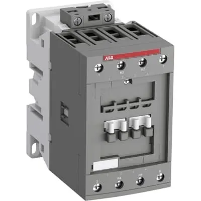
ABB 1SBL341501R4200 Contactor is a four-pole power switch for motor control in industrial automation. This device simplifies control wiring and reduces downtime with screw terminals and a block design that accepts add-on auxiliary blocks. Engineers often struggle with compatibility across control voltages and mounting options; this model supports 230-240 V AC at 50/60 Hz or 277 V at 60 Hz, while the main circuit tolerates up to 690 V. It carries global certifications including CE, UL/CSA, and CB, with IP protection considerations for terminals. The combination of a compact footprint and robust electrical ratings delivers reliable performance in automation panels and machine builds, while enabling scalable control solutions for evolving production lines.
Product Information
Extended Description
1SBL341501R4200 ABB: The AFC40-22-00-42 is a 4-pole (2 N.O + 2 N.C) - 690 V IEC or 600 V UL contactor with Screw terminals, mainly controlling power circuits up to 70 A (IEC AC-1) or 60 A UL general use. Within the AF platform, AFC contactors offer an optimized operating time for AC controlled applications with electromagnetic coil (control voltage : 230 ... 240 V AC 50 Hz / 277 V AC 60 Hz). AFC contactors have a block type design and can be easily extended with add-on auxiliary contact blocks and a wide range of additionnal accessories.
Minimum Order Quantity
1 piece
Customs Tariff Number
85364900
Data Sheet, Technical Information
1SBC100219C0201 AFC contactors for AC control applications_Catalog PDF
Instructions and Manuals
Installation instructions AF(C)40(B)...80(B)-40/22 Contactors, CA4, CAL4, CAT4, CC4, LDC4 Accessories
Instructions and Manuals (Part 2)
Contactors and Overload relays guide
Product Net Width
70 mm
Product Net Depth / Length
119.5 mm
Product Net Height
113.5 mm
Product Net Weight
1.18 kg
Number of Main Contacts NO
2
Number of Main Contacts NC
2
Number of Auxiliary Contacts NO
0
Number of Auxiliary Contacts NC
0
Number of Poles
4P
Standards
IEC/EN 60947-1, IEC/EN 60947-4-1, UL 60947-1, UL 60947-4-1, CSA C22.2 No. 60947-1, CSA C22.2 No. 60947-4-1
Rated Operational Voltage
Main Circuit 690 V
Rated Frequency (f)
Auxiliary Circuit 50 / 60 Hz | Main Circuit 50 / 60 Hz
Conventional Free-air Thermal Current (Ith)
acc. to IEC 60947-4-1, Open Contactors Θ = 40 °C 105 A
Rated Operational Current AC-1 (Ie)
(690 V) 40 °C 70 A | (690 V) 60 °C 60 A | (690 V) 70 °C 50 A
Rated Operational Current AC-3 (Ie)
(415 V) 60 °C 40 A | (440 V) 60 °C 40 A | (500 V) 60 °C 35 A | (690 V) 60 °C 25 A | (380 / 400 V) 60 °C 40 A | (220 / 230 / 240 V) 60 °C 40 A
Rated Operational Power AC-3 (Pe)
(415 V) 22 kW | (440 V) 22 kW | (500 V) 22 kW | (690 V) 22 kW | (380 / 400 V) 18.5 kW | (220 / 230 / 240 V) 11 kW
Rated Short-time Withstand Current Low Voltage (Icw)
at 40 °C Ambient Temp, in Free Air, from a Cold State 15 min 110 A | at 40 °C Ambient Temp, in Free Air, from a Cold State 1 min 250 A | at 40 °C Ambient Temp, in Free Air, from a Cold State 1 s 1000 A | at 40 °C Ambient Temp, in Free Air, from a Cold State 30 s 350 A
Maximum Breaking Capacity
cos phi=0.45 (cos phi=0.35 for Ie > 100 A) at 440 V 950 A | cos phi=0.45 (cos phi=0.35 for Ie > 100 A) at 690 V 600 A
Rated Insulation Voltage (Ui)
acc. to IEC 60947-4-1 and VDE 0110 (Gr. C) 690 V | acc. to UL/CSA 600 V
Rated Impulse Withstand Voltage (Uimp)
Auxiliary Circuit 6 kV
Maximum Electrical Switching Frequency
(AC-1) 600 cycles per hour
Maximum Mechanical Switching Frequency
3600 cycles per hour
Rated Control Circuit Voltage (Uc)
50 Hz 230 ... 240 V | 60 Hz 277 V
Coil Consumption
Average Holding Value 50 / 60 Hz 20 V·A | Average Pull-in Value 50 Hz 150 V·A | Average Pull-in Value 60 Hz 151 V·A
Power Loss
at Rated Operating Conditions AC-1 per Pole 3 W | at Rated Operating Conditions AC-3 per Pole 1 W
Operate Time
Between Coil De-energization and NC Contact Closing 19 ... 105 ms | Between Coil De-energization and NO Contact Opening 4 ... 14 ms | Between Coil Energization and NC Contact Opening 38 ... 95 ms | Between Coil Energization and NO Contact Closing 7 ... 21 ms
Mounting on DIN Rail
TH35-15 (35 x 15 mm Mounting Rail) acc. to IEC 60715 | TH35-7.5 (35 x 7.5 mm Mounting Rail) acc. to IEC 60715
Mounting by Screws (not supplied)
2 x M4 or 2 x M6 screws placed diagonally
Connecting Capacity Main Circuit
Flexible with Ferrule 1/2x 4 ... 35 mm² | Flexible with Insulated Ferrule 1/2x 4 ... 35 mm² | Rigid 1/2x 6 ... 3 5 mm² | Rigid 1/2x 6 ... 35 mm²
Connecting Capacity Control Circuit
Flexible with Ferrule 1/2x 0.75 ... 2.5 mm² | Flexible with Insulated Ferrule 1x 0.75 ... 2.5 mm² | Flexible with Insulated Ferrule 2x 0.75 ... 1.5 mm² | Rigid 1/2x 1 ... 2.5 mm²
Wire Stripping Length
Control Circuit 10 mm | Main Circuit 16 mm
Degree of Protection
acc. to IEC 60529, IEC 60947-1, EN 60529 Auxiliary Terminals IP20 | acc. to IEC 60529, IEC 60947-1, EN 60529 Coil Terminals IP20 | acc. to IEC 60529, IEC 60947-1, EN 60529 Main Terminals IP10
Recommended Screw Driver
Main Circuit 6.5 | Main Circuit Slot | Control Circuit 5.5 | Control Circuit Slot
Tightening Torque
Control Circuit 1.2 N·m | Main Circuit 4 N·m
Terminal Type
Screw Terminals
Product Name
Block Contactor
Maximum Operating Voltage UL/CSA
Main Circuit 600 V
General Use Rating UL/CSA
(600 V AC) 60 A
Tightening Torque UL/CSA
Control Circuit 11 in·lb | Main Circuit 35 in·lb
Ambient Air Temperature
Close to Contactor for Storage -60 ... +80 °C | Near Contactor for Operation in Free Air -40 ... 70 °C | Near Contactor for Operation in Free Air (0.85 ... 1.1 Uc) -40 ... +60 °C | Near Contactor for Operation in Free Air (Uc) -40 ... 70 °C
Climatic Withstand
Category B according to IEC 60947-1 Annex Q
Maximum Operating Altitude Permissible
Without Derating 3000 m
Pollution Degree
3
REACH Declaration
REACH - Letter of Confirmation for block contactors, contactor relays, installation contactors, mini contactors, mini contactor relays, thermal overload relays, electronic overload relays and related accessories
RoHS Information
RoHS II declaration for block contactors, installation contactors, mini contactors, mini contactor relays, thermal overload relays, electronic overload relays and related accessories
RoHS Status
Following EU Directive 2011/65/EU and Amendment 2015/863 July 22, 2019
Toxic Substances Control Act - TSCA
Toxic Substances Control Act (TSCA) declaration for Contactors
WEEE B2C / B2B
Business To Business
WEEE Category
5. Small Equipment (No External Dimension More Than 50 cm)
BV Certificate
BV_2634H36994B1
CB Certificate
CB Certificate AFC40, AFC52, AFC65 3 or 4-pole contactors
CCC Certificate
CCC Declaration of Conformity, Contactor, AF(C)40, AF52(C), AF65(C),AFC78 Made in China
Declaration of Conformity - CE
EU Declaration of Conformity AFC09 ... AFC80 4-pole Contactors
Declaration of Conformity - UKCA
UK Declaration of Conformity AFC09 ... AFC80 4-pole Contactors
DNV Certificate
DNV Certificate AFC09...96 3-pole & AFC09...80 4-pole contactors with screw, push-in terminals
RINA Certificate
Rina Certificate for AFC09...AFC96 3 pole and 4 pole contactors, NFC relays ,screw and spring terminals
UL Certificate
UL-CA Certificate of Compliance AFC40 ... AFC80 4-pole contactors | UL-US Certificate of Compliance AFC40 ... AFC80 4-pole contactors
Package Level 1 Units
box 1 piece
Package Level 1 Width
146.5 mm
Package Level 1 Depth / Length
96.5 mm
Package Level 1 Height
146.5 mm
Package Level 1 Gross Weight
1.3 kg
Package Level 1 EAN
3471523023369
Object Classification Code
Q
ETIM 7
EC000066 - Power contactor, AC switching
ETIM 8
EC000066 - Power contactor, AC switching
ETIM 9
EC000066 - Power contactor, AC switching
eClass
V11.0 : 27371003
UNSPSC
39121529
IDEA Granular Category Code (IGCC)
4755 >> Contactors
Feature: four-pole configuration with two normally open and two normally closed contacts. Business Impact: enables reliable sequencing and safe motor control in complex circuits, reducing cross-wiring and misoperation. Application: drives, conveyors, and pump systems where both start/stop and interlock are required. Feature: coil voltage options of 230-240 V AC 50/60 Hz or 277 V AC 60 Hz. Business Impact: flexible integration across control panels and legacy systems, minimizing interposing relays and wiring. Application: panel builders and OEMs upgrading controls without rewiring. Feature: main circuit rated up to 690 V and Ith of 105 A. Business Impact: supports high-power loads with predictable thermal performance, boosting equipment uptime. Application: motors, pumps, and power distribution in manufacturing lines. Feature: compact DIN-rail and screw-mount compatibility (TH35-15 or TH35-7.5). Business Impact: simplifies installation and reduces cabinet depth, lowering enclosure costs. Application: machine retrofits and new control panels with tight space constraints. Feature: screw terminals and flexible conductor connections for main and control circuits. Business Impact: offers sturdy, vibration-resistant terminations and easy field maintenance. Application: heavy-duty industrial environments with frequent wiring checks. Feature: modularity with add-on auxiliary contact blocks and accessories. Business Impact: protects control logic through wiring options and extendable functionality. Application: automation systems requiring expandability. Feature: energy-efficient coil consumption and defined power loss per pole. Business Impact: lowers operating energy during long-on cycles, reducing heat inside control cabinets. Application: continuous operation in conveyors and material handling. Feature: broad certifications and RoHS/REACH compliance. Business Impact: simplifies global procurement and regulatory compliance. Application: multi-region deployments across CE/UL/CSA markets.
Get a Quick Quote for a ABB 1SBL341501R4200
Chat with us on WhatsApp - fast responses guaranteed
Need to speak with someone? We'll call you back within 2 hours during business hours
Interested in ABB 1SBL341501R4200?
Enquire Now
FAQs
The device supports TH35-15 and TH35-7.5 DIN rails for quick mounting and also allows mounting by screws (2 x M4 or 2 x M6 diagonally). During installation, target a DIN-rail position for compact panels or use screw mounting where rails aren’t feasible. Use the recommended torque values: 4 N·m for the main circuit terminals and 1.2 N·m for the control circuit to ensure reliable connections.
For AC-1 at 690 V, the rated operational current Ie is 70 A at 40 °C, 60 A at 60 °C, and 50 A at 70 °C. For AC-3, ratings include 40 A at 415–440–500–690 V depending on temperature. These values guide motor starting and switching loads and help in selecting appropriate protective devices.
The coil is available as 230-240 V AC at 50/60 Hz with a 277 V option at 60 Hz. Use the 230-240 V coil for standard control circuits in North American or European mains, and the 277 V coil for systems that operate at 277 V control voltage. This flexibility simplifies integration with existing control cabinets.
Auxiliary terminals have IP20 protection, while main terminals are IP10. The device is designed to operate in free-air conditions with a thermal and climatic range suitable for typical industrial environments. When wiring, observe proper enclosure ingress protection and keep terminals clean and dry to maintain performance.
The product carries CE, UL/CSA certifications, and CB documentation for global compliance. It also aligns with IEC/EN 60947-1, IEC/EN 60947-4-1, and related UL standards, with RoHS and REACH declarations. These certifications support cross-region deployments in automated facilities and assist in regulatory audits.