ABB 1SBL347001N1111 Block Contactor - UL 60335-2-40 Certified
Part Number: 1SBL347001N1111
Quick Summary
ABB 1SBL347001N1111 Block Contactor is a three-pole device for motor control in industrial automation and conveyor systems. Engineers face voltage swings and transient spikes that cause nuisance trips, so this model uses AF technology with a wide control voltage range and built-in surge protection to keep operations stable. It carries CE and UL/CSA certifications along with CB and CCC documentation, plus IP20 coil protection and IP10 main terminals for robust safety. Compatible with add-on auxiliary contact blocks and DIN-rail mounting, it delivers compact, energy-efficient control in demanding environments while simplifying panel design and serviceability.
Product Information
Extended Description
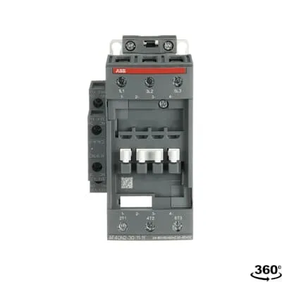
1SBL347001N1111 ABB: The AF40N2-30-11-11 is a 3 pole - 600 V UL, NEMA size N2 contactor with pre-mounted auxiliary contacts and Screw, switching power circuits up to 60 A UL general use. Thanks to the AF technology, the contactor has a wide control voltage range (24-60 V 50/60 Hz and 20-60 V DC), managing large control voltage variations, reducing panel energy consumptions and ensuring distinct operations in unstable networks. Furthermore, surge protection is built-in, offering a compact solution. AF contactors have a block type design, can be easily extended with add-on auxiliary contact blocks and an additional wide range of accessories.
Minimum Order Quantity
1 piece
Instructions and Manuals
Installation instructions AF(C)40(B)...96(B)-30 Contactors, CA4, CAL4, CAT4, CC4, LDC4 Accessories
Instructions and Manuals (Part 2)
Contactors and Overload relays guide
CAD Dimensional Drawing
Information - 2D and 3D files for CAD systems
Product Net Width
67 mm
Product Net Depth / Length
111 mm
Product Net Height
125.5 mm
Product Net Weight
1.01 kg
Number of Main Contacts NO
3
Number of Main Contacts NC
0
Number of Auxiliary Contacts NO
1
Number of Auxiliary Contacts NC
1
Number of Poles
3P
Standards
IEC/EN 60947-1, IEC/EN 60947-4-1, UL 60335-2-40 LZGH2 A2L, UL 60947-1, UL 60947-4-1, CSA C22.2 No. 60335-2-40 LZGH2 A2L, CSA C22.2 No. 60947-1:22, CSA C22.2 No. 60947-4-1:22
Rated Operational Voltage
Auxiliary Circuit 690 V | Main Circuit 690 V
Rated Frequency (f)
Auxiliary Circuit 50 / 60 Hz | Control Circuit 50 / 60 Hz | Main Circuit 50 / 60 Hz
Conventional Free-air Thermal Current (Ith)
acc. to IEC 60947-4-1, Open Contactors Θ = 40 °C 105 A | acc. to IEC 60947-5-1, Θ = 40 °C 16 A
Rated Operational Current AC-1 (Ie)
(690 V) 40 °C 70 A | (690 V) 60 °C 60 A | (690 V) 70 °C 50 A
Rated Operational Current AC-3 (Ie)
(415 V) 60 °C 40 A | (440 V) 60 °C 40 A | (500 V) 60 °C 35 A | (690 V) 60 °C 25 A | (380 / 400 V) 60 °C 40 A | (220 / 230 / 240 V) 60 °C 40 A
Rated Operational Current AC-3e (Ie)
(415 V) 60 °C 40 A | (440 V) 60 °C 40 A | (500 V) 60 °C 35 A | (690 V) 60 °C 25 A | (380 / 400 V) 60 °C 40 A | (220 / 230 / 240 V) 60 °C 40 A
Rated Operational Current AC-15 (Ie)
(500 V) 2 A | (690 V) 2 A | (24 / 127 V) 6 A | (220 / 240 V) 4 A | (400 / 440 V) 3 A
Rated Operational Current DC-13 (Ie)
(24 V) 6 A / 144 W | (48 V) 2.8 A / 134 W | (72 V) 1 A / 72 W | (110 V) 0.55 A / 60 W | (125 V) 0.55 A / 69 W | (220 V) 0.27 A / 60 W | (250 V) 0.27 A / 68 W | (400 V) 0.15 A / 60 W | (500 V) 0.13 A / 65 W | (600 V) 0.1 A / 60 W
Rated Operational Power AC-3 (Pe)
(400 V) 18.5 kW | (415 V) 22 kW | (440 V) 22 kW | (500 V) 22 kW | (690 V) 22 kW | (380 / 400 V) 18.5 kW | (220 / 230 / 240 V) 11 kW
Rated Operational Power AC-3e (Pe)
(415 V) 22 kW | (440 V) 22 kW | (500 V) 22 kW | (690 V) 22 kW | (380 / 400 V) 18.5 kW | (220 / 230 / 240 V) 11 kW
Rated Short-time Withstand Current Low Voltage (Icw)
at 40 °C Ambient Temp, in Free Air, from a Cold State 10 s 600 A | at 40 °C Ambient Temp, in Free Air, from a Cold State 15 min 110 A | at 40 °C Ambient Temp, in Free Air, from a Cold State 1 min 250 A | at 40 °C Ambient Temp, in Free Air, from a Cold State 1 s 1000 A | at 40 °C Ambient Temp, in Free Air, from a Cold State 30 s 350 A | for 0.1 s 140 A | for 1 s 100 A
Maximum Breaking Capacity
cos phi=0.45 (cos phi=0.35 for Ie > 100 A) at 440 V 950 A | cos phi=0.45 (cos phi=0.35 for Ie > 100 A) at 690 V 600 A
Rated Insulation Voltage (Ui)
acc. to IEC 60947-4-1 690 V | acc. to IEC 60947-5-1 690 V | acc. to UL/CSA 600 V
Rated Impulse Withstand Voltage (Uimp)
6 kV
Maximum Electrical Switching Frequency
(AC-1) 600 cycles per hour | (AC-15) 1200 cycles per hour | (AC-2 / AC-4) 150 cycles per hour | (AC-3) 1200 cycles per hour | (DC-13) 900 cycles per hour
Maximum Mechanical Switching Frequency
3600 cycles per hour
Rated Control Circuit Voltage (Uc)
50 Hz 24 ... 60 V | 60 Hz 24 ... 60 V | DC Operation 20 ... 60 V
Power Loss
at 6 A per Pole 0.1 W | at Rated Operating Conditions AC-1 per Pole 3 W | at Rated Operating Conditions AC-3 per Pole 1 W
Operate Time
Between Coil De-energization and NC Contact Closing 19 ... 105 ms | Between Coil De-energization and NO Contact Opening 17 ... 100 ms | Between Coil Energization and NC Contact Opening 38 ... 95 ms | Between Coil Energization and NO Contact Closing 42 ... 100 ms
Mounting on DIN Rail
TH35-15 (35 x 15 mm Mounting Rail) acc. to IEC 60715 | TH35-7.5 (35 x 7.5 mm Mounting Rail) acc. to IEC 60715
Mounting by Screws (not supplied)
2 x M4 or 2 x M6 screws placed diagonally
Connecting Capacity Main Circuit
Flexible with Ferrule 1/2x 4 ... 35 mm² | Flexible with Insulated Ferrule 1/2x 4 ... 35 mm² | Rigid Stranded 1/2x 6 ... 35 mm²
Connecting Capacity Auxiliary Circuit
Flexible with Ferrule 1/2x 0.75 ... 2.5 mm² | Flexible with Insulated Ferrule 2x 0.75 ... 1.5 mm² | Flexible with Insulated Ferrule 1x 0.75 ... 2.5 mm² | Rigid 1/2x 1 ... 2.5 mm²
Connecting Capacity Control Circuit
Flexible with Ferrule 1/2x 0.75 ... 2.5 mm² | Flexible with Insulated Ferrule 1x 0.75 ... 2.5 mm² | Flexible with Insulated Ferrule 2x 0.75 ... 1.5 mm² | Rigid Solid 1/2x 1 ... 2.5 mm² | Rigid Stranded 1/2x 1 ... 2.5 mm²
Wire Stripping Length
Auxiliary Circuit 10 mm | Control Circuit 10 mm | Main Circuit 16 mm
Degree of Protection
acc. to IEC 60529, IEC 60947-1, EN 60529 Auxiliary Terminals IP20 | acc. to IEC 60529, IEC 60947-1, EN 60529 Coil Terminals IP20 | acc. to IEC 60529, IEC 60947-1, EN 60529 Main Terminals IP10
Tightening Torque
Auxiliary Circuit 1.2 N·m | Control Circuit 1.2 N·m | Main Circuit 4 N·m
Terminal Type
Screw Terminals
Product Name
Block Contactor
NEMA Size
2
Continuous Current Rating NEMA
45 A
Horsepower Rating NEMA
(115 V AC) Single Phase 3 Hp | (200 V AC) Three Phase 10 Hp | (230 V AC) Single Phase 7-1/2 Hp | (230 V AC) Three Phase 15 Hp | (460 V AC) Three Phase 25 Hp | (575 V AC) Three Phase 25 Hp
Maximum Operating Voltage UL/CSA
Main Circuit 600 V
General Use Rating UL/CSA
(600 V AC) 60 A
Connecting Capacity Main Circuit UL/CSA
Rigid Stranded 1/2x 10-2 AWG
Connecting Capacity Control Circuit UL/CSA
Rigid Solid 1/2x 18-14 AWG | Rigid Stranded 1/2x 18-14 AWG
Tightening Torque UL/CSA
Auxiliary Circuit 11 in·lb | Control Circuit 11 in·lb | Main Circuit 35 in·lb
Full Load Amps Motor Use
(120 V AC) Single Phase 3 A | (200 ... 208 V AC) Three Phase 10 A | (220 ... 240 V AC) Three Phase 15 A | (240 V AC) Single Phase 7-1/2 A | (440 ... 480 V AC) Three Phase 30 A | (550 ... 600 V AC) Three Phase 40 A
Ambient Air Temperature
Close to Contactor Fitted with Thermal O/L Relay -40 ... 70 °C | Close to Contactor without Thermal O/L Relay -40 ... 70 °C | Close to Contactor for Storage -60 ... +80 °C
Climatic Withstand
Category B according to IEC 60947-1 Annex Q
Maximum Operating Altitude Permissible
Without Derating 3000 m
Resistance to Shock acc. to IEC 60068-2-27
Closed, Shock Direction: A 25 g | Closed, Shock Direction: B1 25 g | Closed, Shock Direction: B2 15 g | Closed, Shock Direction: C1 25 g | Closed, Shock Direction: C2 25 g | Open, Shock Direction: A 25 g | Open, Shock Direction: B1 5 g | Open, Shock Direction: B2 15 g | Open, Shock Direction: C1 25 g | Open, Shock Direction: C2 25 g
Resistance to Vibrations
3g Closed Position & 3g Open Position 5 ... 300 Hz
Pollution Degree
3
Conflict Minerals Reporting Template (CMRT)
CMRT - Conflict Minerals Reporting Template
REACH Declaration
REACH - Letter of Confirmation for block contactors, contactor relays, installation contactors, mini contactors, mini contactor relays, thermal overload relays, electronic overload relays and related accessories
RoHS Information
RoHS II declaration for block contactors, installation contactors, mini contactors, mini contactor relays, thermal overload relays, electronic overload relays and related accessories
RoHS Status
Following EU Directive 2011/65/EU and Amendment 2015/863 July 22, 2019
Toxic Substances Control Act - TSCA
Toxic Substances Control Act (TSCA) declaration for Contactors
WEEE Category
Product Not in WEEE Scope
ABB EcoSolutions
Yes
End Of Life Disassembling Instructions
End of life instruction AF(S)40/52/65/80/96(B)(RT) Contactors
Sustainable Material Content in Packaging (wt. %)
FSC Recycled Paper - 94.6 %
Sustainable Material Content in Product (wt. %)
Recycled Metal - 28.2 %
A2L Certificate – UL
UL-US Certificate of Compliance AF40 ... AF96 3-pole contactors - UL 60335-2-40 Household and Similar Electrical Appliances - Safety - Part 2-40: Particular Requirements for Electrical Heat Pumps, Air-Conditioners and Dehumidifiers | UL-CA Certificate of Compliance AF40 ... AF96 3-pole contactors - CSA C22.2 No. 60335-2-40 Household and Similar Electrical Appliances - Safety - Part 2-40: Particular Requirements for Electrical Heat Pumps, Air-Conditioners and Dehumidifiers
CB Certificate
CB Certificate AF(S)40(B), (S)AF52(B), AF(S)65(B) 3 and 4-pole contactors
CCC Certificate
CQC Certificate, Contactor, AF*40-30-**-**, AF40-40-**-**, AF40-22-**-**, AF*52-30-**-**, AF52-40-**-**,AF*65-30-**-**, Made in France
CQC Certificate
CQC Certificate, Contactor, AF*40-30-**-**, AF40-40-**-**, AF40-22-**-**, AF*52-30-**-**, AF52-40-**-**,AF*65-30-**-**, Made in France | CQC Certificate, Contactor, AF40, AF52, AF65, AFC40, AFC52, AFC65, Made in China
Declaration of Conformity - CCC
CCC Declaration of Conformity, Contactor, AF*40-30-**-**, AF40-40-**-**, AF40-22-**-**, AF*52-30-**-**, AF52-40-**-**,AF*65-30-**-**, Made in France | CCC Declaration of Conformity, Contactor, AF(C)40, AF52(C), AF65(C),AFC78 Made in China
Declaration of Conformity - CE
EU Declaration of Conformity AF09N ... AF80N NEMA contactors
Declaration of Conformity - UKCA
UK Declaration of Conformity AF09N ... AF80N NEMA contactors
UL Certificate
UL-US-L312527-1141-10303102-9 | UL-CA-L312527-4141-10303102-9
UL Listing Card
UL_E312527
Package Level 1 Units
box 1 piece
Package Level 1 Width
150 mm
Package Level 1 Depth / Length
150 mm
Package Level 1 Height
97 mm
Package Level 1 Gross Weight
1.11 kg
Package Level 1 EAN
3471523016637
Package Level 3 Units
240 piece
Object Classification Code
Q
ETIM 7
EC000066 - Power contactor, AC switching
ETIM 8
EC000066 - Power contactor, AC switching
ETIM 9
EC000066 - Power contactor, AC switching
eClass
V11.0 : 27371003
UNSPSC
39121529
Feature → Business Impact → Application: The 3P AF40N2-30-11-11 design delivers reliable power switching with a wide control voltage range of 24–60 V AC/60 Hz and 20–60 V DC, reducing control circuit failures and energy waste in variable networks. This translates to fewer trips in conveyors and pumps and lower energy consumption in the control panel. Application: Motor control for conveyors, pumps, and fans in manufacturing lines. Feature → Business Impact → Application: Built-in surge protection provides enhanced protection against voltage spikes, mitigating equipment damage and extending component life in harsh electrical environments. Application: Industrial automation enclosures and machine control stations. Feature → Business Impact → Application: DIN rail mounting and screw terminal connections simplify installation and future expansion, enabling quick updates to add-on auxiliary blocks as line demands evolve. Application: System integrators and panel builders seeking scalable control solutions. Feature → Business Impact → Application: Compliance with IEC/UL/CSA standards and IP ratings ensures regulatory alignment and safer operation in production floors, reducing audit risk. Application: Global deployments requiring CE, UL/CSA certifications and robust environmental specs. Feature → Business Impact → Application: Comprehensive terminal and wire-size guidance (Main, Auxiliary, and Control circuits) supports reliable field wiring, reducing commissioning time and field faults. Application: New installations and retrofits in electrical protection and circuit control.
Get a Quick Quote for a ABB 1SBL347001N1111
Chat with us on WhatsApp - fast responses guaranteed
Need to speak with someone? We'll call you back within 2 hours during business hours
Interested in ABB 1SBL347001N1111?
Enquire Now
FAQs
Yes. It supports DIN rail mounting using TH35-15 or TH35-7.5 rails and uses screw terminals for main, auxiliary, and control circuits. Main circuit accepts flexible ferrule 1/2x 4-35 mm² or rigid 1/2x 6-35 mm², while auxiliary and control circuits accept 0.75–2.5 mm² ferrules or rigid options, simplifying field wiring.
Main circuit rated for 690 V with AC-1 up to 70 A and AC-3 up to 40 A at 415–690 V depending on temperature. Auxiliary circuit includes one NO and one NC contact with a 690 V rating and a control circuit rated for 24–60 V AC/DC, ensuring versatile control and signaling alongside power switching.
Yes. It offers a high conventional free-air rating and a maximum short-time withstand current (I cw) up to 1000 A for short durations, making it suitable for initiating motors and handling brief inrush surges. Its 3-pole configuration, coil voltage range, and surge protection support reliable operation in pump and conveyor applications.
The device is documented with CE and UK CA declarations, UL/CSA listings, CB and CCC certificates, and RoHS/REACH compliance. It also has UL 60335-2-40 safety alignment for household and similar appliances, with DoC and other conformity documentation for global procurement.
The wide control voltage range reduces coil energy variations and panel energy consumption, lowering overall operating costs. Built-in surge protection reduces downtime from transient events, while modular auxiliary contacts simplify expansion. Mounting on a standard DIN rail and the robust IP ratings ease maintenance and spare-part planning for long-term ROI.