ABB 1SBL367061R1211 Block Contactor - AF Technology
Part Number: 1SBL367061R1211
Quick Summary
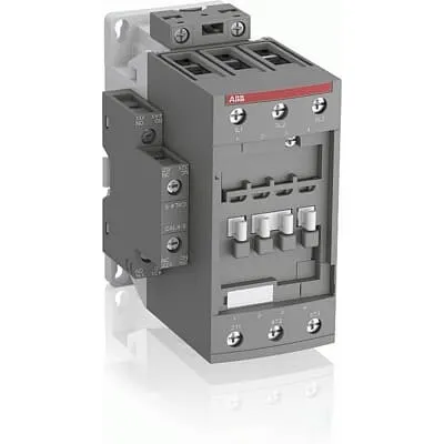
ABB AF Contactor 1SBL367061R1211 is a rugged three-pole motor control device for industrial automation. In networks with voltage swings, its control range of 48–130 V AC/DC minimizes nuisance tripping and reduces panel energy waste. It carries IEC/EN 60947-1 and 60947-4-1 approvals, UL 60335-2-40 and CSA/CE certifications, with UKCA added where required, ensuring global compliance. The compact block design with add-on auxiliary blocks and built-in surge protection simplifies installation and future expansion, delivering lower lifecycle costs and higher uptime. For panel builders and end users, this ABB solution reliably controls motors in conveyors, pumps, fans, and rolling stock applications while aligning with common procurement standards.
Product Information
Extended Description
1SBL367061R1211 ABB: The AF52B-30-11-12 is a 3 pole - 690 V IEC or 600 UL contactor with pre-mounted auxiliary contacts and screw terminals, controlling motors up to 22 kW / 400 V AC (AC-3) or 40 hp / 480 V UL and switching power circuits up to 100 A (AC-1) or 80 A UL general use. Thanks to the AF technology, the contactor has a wide control voltage range (48-130 V 50/60 Hz and DC), managing large control voltage variations, reducing panel energy consumptions and ensuring distinct operations in unstable networks. Furthermore, surge protection is built-in, offering a compact solution. AF contactors have a block type design, can be easily extended with add-on auxiliary contact blocks and an additional wide range of accessories.
Minimum Order Quantity
1 piece
Customs Tariff Number
85364900
Data Sheet, Technical Information
Motor control and protection for Rolling stock application_PDF
Instructions and Manuals
Installation instructions AF(C)40(B)...96(B)-30 Contactors, CA4, CAL4, CAT4, CC4, LDC4 Accessories
Instructions and Manuals (Part 2)
Contactors and Overload relays guide
CAD Dimensional Drawing
Information - 2D and 3D files for CAD systems
Product Net Width
67 mm
Product Net Depth / Length
111 mm
Product Net Height
125.5 mm
Product Net Weight
1.01 kg
Number of Main Contacts NO
3
Number of Main Contacts NC
0
Number of Auxiliary Contacts NO
1
Number of Auxiliary Contacts NC
1
Number of Poles
3P
Standards
IEC/EN 60947-1, IEC/EN 60947-4-1, UL 60335-2-40 LZGH2 A2L, UL 60947-1, UL 60947-4-1, CSA C22.2 No. 60335-2-40 LZGH2 A2L, CSA C22.2 No. 60947-1:22, CSA C22.2 No. 60947-4-1:22, IEC 60077-1 (applicable parts), IEC 60077-2 (applicable parts), EN 50155 (applicable parts), IEC 61373, For compliance confirmation on applicable parts based on your application and combination, please consult your ABB sales representatives.
Rated Operational Voltage
Auxiliary Circuit 690 V | Main Circuit 690 V
Rated Frequency (f)
Auxiliary Circuit 50 / 60 Hz | Control Circuit 50 / 60 Hz | Main Circuit 50 / 60 Hz
Conventional Free-air Thermal Current (Ith)
acc. to IEC 60947-4-1, Open Contactors Θ = 40 °C 105 A | acc. to IEC 60947-5-1, Θ = 40 °C 16 A
Rated Operational Current AC-1 (Ie)
(690 V) 40 °C 100 A | (690 V) 60 °C 80 A | (690 V) 70 °C 70 A
Rated Operational Current AC-3 (Ie)
(415 V) 60 °C 53 A | (440 V) 60 °C 53 A | (500 V) 60 °C 45 A | (690 V) 60 °C 35 A | (380 / 400 V) 60 °C 53 A | (220 / 230 / 240 V) 60 °C 53 A
Rated Operational Current AC-3e (Ie)
(415 V) 60 °C 53 A | (440 V) 60 °C 53 A | (500 V) 60 °C 45 A | (690 V) 60 °C 35 A | (380 / 400 V) 60 °C 53 A | (220 / 230 / 240 V) 60 °C 53 A
Rated Operational Current AC-15 (Ie)
(500 V) 2 A | (690 V) 2 A | (24 / 127 V) 6 A | (220 / 240 V) 4 A | (400 / 440 V) 3 A
Rated Operational Current DC-1 (Ie)
(110 V) 2 Poles in Series, 40 °C 100 A | (110 V) 2 Poles in Series, 60 °C 80 A | (110 V) 2 Poles in Series, 70 °C 70 A | (110 V) 3 Poles in Series, 40 °C 100 A | (110 V) 3 Poles in Series, 60 °C 80 A | (110 V) 3 Poles in Series, 70 °C 70 A | (220 V) 3 Poles in Series, 40 °C 100 A | (220 V) 3 Poles in Series, 60 °C 80 A | (220 V) 3 Poles in Series, 70 °C 70 A | (72 V) 1-Pole, 40 °C 100 A | (72 V) 1-Pole, 60 °C 80 A | (72 V) 1-Pole, 70 °C 70 A | (72 V) 2 Poles in Series, 40 °C 100 A | (72 V) 2 Poles in Series, 60 °C 80 A | (72 V) 2 Poles in Series, 70 °C 70 A | (72 V) 3 Poles in Series, 40 °C 100 A | (72 V) 3 Poles in Series, 60 °C 80 A | (72 V) 3 Poles in Series, 70 °C 70 A
Rated Operational Current DC-3 (Ie)
(110 V) 2 Poles in Series, 40 °C 100 A | (110 V) 2 Poles in Series, 60 °C 80 A | (110 V) 2 Poles in Series, 70 °C 70 A | (110 V) 3 Poles in Series, 40 °C 100 A | (110 V) 3 Poles in Series, 60 °C 80 A | (110 V) 3 Poles in Series, 70 °C 70 A | (220 V) 3 Poles in Series, 40 °C 100 A | (220 V) 3 Poles in Series, 60 °C 80 A | (220 V) 3 Poles in Series, 70 °C 70 A | (72 V) 1-Pole, 40 °C 100 A | (72 V) 1-Pole, 60 °C 80 A | (72 V) 1-Pole, 70 °C 70 A | (72 V) 2 Poles in Series, 40 °C 100 A | (72 V) 2 Poles in Series, 60 °C 80 A | (72 V) 2 Poles in Series, 70 °C 70 A | (72 V) 3 Poles in Series, 40 °C 100 A | (72 V) 3 Poles in Series, 60 °C 80 A | (72 V) 3 Poles in Series, 70 °C 70 A
Rated Operational Current DC-5 (Ie)
(110 V) 2 Poles in Series, 40 °C 100 A | (110 V) 2 Poles in Series, 60 °C 80 A | (110 V) 2 Poles in Series, 70 °C 70 A | (110 V) 3 Poles in Series, 40 °C 100 A | (110 V) 3 Poles in Series, 60 °C 80 A | (110 V) 3 Poles in Series, 70 °C 70 A | (220 V) 3 Poles in Series, 40 °C 100 A | (220 V) 3 Poles in Series, 60 °C 80 A | (220 V) 3 Poles in Series, 70 °C 70 A | (72 V) 1-Pole, 40 °C 100 A | (72 V) 1-Pole, 60 °C 80 A | (72 V) 1-Pole, 70 °C 70 A | (72 V) 2 Poles in Series, 40 °C 100 A | (72 V) 2 Poles in Series, 60 °C 80 A | (72 V) 2 Poles in Series, 70 °C 70 A | (72 V) 3 Poles in Series, 40 °C 100 A | (72 V) 3 Poles in Series, 60 °C 80 A | (72 V) 3 Poles in Series, 70 °C 70 A
Rated Operational Current DC-13 (Ie)
(24 V) 6 A / 144 W | (48 V) 2.8 A / 134 W | (72 V) 1 A / 72 W | (110 V) 0.55 A / 60 W | (125 V) 0.55 A / 69 W | (220 V) 0.27 A / 60 W | (250 V) 0.27 A / 68 W | (400 V) 0.15 A / 60 W | (500 V) 0.13 A / 65 W | (600 V) 0.1 A / 60 W
Rated Operational Power AC-3 (Pe)
(400 V) 22 kW | (415 V) 30 kW | (440 V) 30 kW | (500 V) 30 kW | (690 V) 30 kW | (380 / 400 V) 22 kW | (220 / 230 / 240 V) 15 kW
Rated Operational Power AC-3e (Pe)
(415 V) 30 kW | (440 V) 30 kW | (500 V) 30 kW | (690 V) 30 kW | (380 / 400 V) 22 kW | (220 / 230 / 240 V) 15 kW
Rated Short-time Withstand Current Low Voltage (Icw)
at 40 °C Ambient Temp, in Free Air, from a Cold State 10 s 600 A | at 40 °C Ambient Temp, in Free Air, from a Cold State 15 min 110 A | at 40 °C Ambient Temp, in Free Air, from a Cold State 1 min 250 A | at 40 °C Ambient Temp, in Free Air, from a Cold State 1 s 1000 A | at 40 °C Ambient Temp, in Free Air, from a Cold State 30 s 350 A | for 0.1 s 140 A | for 1 s 100 A
Maximum Breaking Capacity
cos phi=0.45 (cos phi=0.35 for Ie > 100 A) at 440 V 950 A | cos phi=0.45 (cos phi=0.35 for Ie > 100 A) at 690 V 600 A
Rated Insulation Voltage (Ui)
acc. to IEC 60947-4-1 690 V | acc. to IEC 60947-5-1 690 V | acc. to UL/CSA 600 V
Maximum Electrical Switching Frequency
(AC-1) 600 cycles per hour | (AC-15) 1200 cycles per hour | (AC-2 / AC-4) 150 cycles per hour | (AC-3) 1200 cycles per hour | (DC-13) 900 cycles per hour
Maximum Mechanical Switching Frequency
3600 cycles per hour
Rated Control Circuit Voltage (Uc)
50 Hz 48 ... 130 V | 60 Hz 48 ... 130 V | DC Operation 48 ... 130 V
Coil Consumption
Average Holding Value 50 / 60 Hz 4 V·A | Average Holding Value DC 2 W
Power Loss
at Rated Operating Conditions AC-1 per Pole 6.3 W | at Rated Operating Conditions AC-3 per Pole 1.7 W
Operate Time
Between Coil De-energization and NC Contact Closing 19 ... 105 ms | Between Coil De-energization and NO Contact Opening 17 ... 100 ms | Between Coil Energization and NC Contact Opening 38 ... 95 ms | Between Coil Energization and NO Contact Closing 42 ... 100 ms
Mounting on DIN Rail
TH35-15 (35 x 15 mm Mounting Rail) acc. to IEC 60715 | TH35-7.5 (35 x 7.5 mm Mounting Rail) acc. to IEC 60715
Mounting by Screws (not supplied)
2 x M4 or 2 x M6 screws placed diagonally
Connecting Capacity Main Circuit
Flexible with Ferrule 1/2x 4 ... 35 mm² | Flexible with Insulated Ferrule 1/2x 4 ... 35 mm² | Rigid Stranded 1/2x 6 ... 35 mm²
Connecting Capacity Auxiliary Circuit
Flexible with Ferrule 1/2x 0.75 ... 2.5 mm² | Flexible with Insulated Ferrule 1x 0.75 ... 2.5 mm² | Flexible with Insulated Ferrule 2x 0.75 ... 1.5 mm² | Rigid Solid 1/2x 1 ... 2.5 mm² | Rigid Stranded 1/2x 1 ... 2.5 mm²
Connecting Capacity Control Circuit
Flexible with Ferrule 1/2x 0.75 ... 2.5 mm² | Flexible with Insulated Ferrule 1x 0.75 ... 2.5 mm² | Flexible with Insulated Ferrule 2x 0.75 ... 1.5 mm² | Rigid Solid 1/2x 1 ... 2.5 mm² | Rigid Stranded 1/2x 1 ... 2.5 mm²
Wire Stripping Length
Auxiliary Circuit 10 mm | Control Circuit 10 mm | Main Circuit 16 mm
Degree of Protection
acc. to IEC 60529, IEC 60947-1, EN 60529 Auxiliary Terminals IP20 | acc. to IEC 60529, IEC 60947-1, EN 60529 Coil Terminals IP20 | acc. to IEC 60529, IEC 60947-1, EN 60529 Main Terminals IP10
Recommended Screw Driver
Pozidriv PZ
Tightening Torque
Auxiliary Circuit 1.2 N·m | Control Circuit 1.2 N·m | Main Circuit 4 N·m
Terminal Type
Screw Terminals
Product Name
Block Contactor
Continuous Current Rating NEMA
0 A
Maximum Operating Voltage UL/CSA
Main Circuit 600 V
General Use Rating UL/CSA
(600 V AC) 80 A
Horsepower Rating UL/CSA
(120 V AC) Single Phase 3 hp | (200 ... 208 V AC) Three Phase 15 hp | (220 ... 240 V AC) Three Phase 20 hp | (240 V AC) Single Phase 10 hp | (440 ... 480 V AC) Three Phase 40 hp | (550 ... 600 V AC) Three Phase 50 hp
Connecting Capacity Main Circuit UL/CSA
Rigid Stranded 1/2x 10-2 AWG
Connecting Capacity Control Circuit UL/CSA
Rigid Solid 1/2x 18-14 AWG | Rigid Stranded 1/2x 18-14 AWG
Tightening Torque UL/CSA
Auxiliary Circuit 11 in·lb | Control Circuit 11 in·lb | Main Circuit 35 in·lb
Full Load Amps Motor Use
(120 V AC) Single Phase 34 A | (200 ... 208 V AC) Three Phase 48.3 A | (220 ... 240 V AC) Three Phase 54 A | (240 V AC) Single Phase 50 A | (440 ... 480 V AC) Three Phase 52 A | (550 ... 600 V AC) Three Phase 52 A
Ambient Air Temperature
Close to Contactor Fitted with Thermal O/L Relay -40 ... 70 °C | Close to Contactor without Thermal O/L Relay -40 ... 70 °C | Close to Contactor for Storage -60 ... +80 °C
Climatic Withstand
Category B according to IEC 60947-1 Annex Q
Maximum Operating Altitude Permissible
Without Derating 3000 m
Shock and Vibration Withstand acc. to IEC 61373
Category 1, Class B
Pollution Degree
3
REACH Declaration
REACH - Letter of Confirmation for block contactors, contactor relays, installation contactors, mini contactors, mini contactor relays, thermal overload relays, electronic overload relays and related accessories
RoHS Information
RoHS II declaration for block contactors, installation contactors, mini contactors, mini contactor relays, thermal overload relays, electronic overload relays and related accessories
RoHS Status
Following EU Directive 2011/65/EU and Amendment 2015/863 July 22, 2019
Toxic Substances Control Act - TSCA
Toxic Substances Control Act (TSCA) declaration for Contactors
WEEE B2C / B2B
Business To Business
WEEE Category
5. Small Equipment (No External Dimension More Than 50 cm)
ABB EcoSolutions
Yes
End Of Life Disassembling Instructions
End of life instruction AF(S)40/52/65/80/96(B)(RT) Contactors
Environmental Product Declaration - EPD
Environmental Product Declaration AF(S)40(B), AF(S)52(B), AF(S)65(B) (FR)
Sustainable Material Content in Packaging (wt. %)
FSC Recycled Paper - 94.6 %
Sustainable Material Content in Product (wt. %)
Recycled Metal - 28.2 %
A2L Certificate – UL
UL-US Certificate of Compliance AF40 ... AF96 3-pole contactors - UL 60335-2-40 Household and Similar Electrical Appliances - Safety - Part 2-40: Particular Requirements for Electrical Heat Pumps, Air-Conditioners and Dehumidifiers | UL-CA Certificate of Compliance AF40 ... AF96 3-pole contactors - CSA C22.2 No. 60335-2-40 Household and Similar Electrical Appliances - Safety - Part 2-40: Particular Requirements for Electrical Heat Pumps, Air-Conditioners and Dehumidifiers
CB Certificate
CB Certificate AF(S)40(B), (S)AF52(B), AF(S)65(B) 3 and 4-pole contactors
CCC Certificate
CQC Certificate, Contactor, AF*40-30-**-**, AF40-40-**-**, AF40-22-**-**, AF*52-30-**-**, AF52-40-**-**,AF*65-30-**-**, Made in France
Declaration of Conformity - CE
EU Declaration of Conformity AF09 ... AF38(Z)B..(K), AF40B ... AF96B 3 and 4-pole contactors
Declaration of Conformity - UKCA
UK Declaration of Conformity AF09 ... AF38(Z)B..(K), AF40B ... AF96B 3 and 4-pole contactors
UL Certificate
UL-US-L312527-1141-10303102-9 | UL-CA-L312527-4141-10303102-9
Package Level 1 Units
box 1 piece
Package Level 1 Width
150 mm
Package Level 1 Depth / Length
150 mm
Package Level 1 Height
97 mm
Package Level 1 Gross Weight
1.11 kg
Package Level 1 EAN
3471523024991
Package Level 2 Units
box 10 piece
Package Level 2 Width
250 mm
Package Level 2 Depth / Length
300 mm
Package Level 2 Height
300 mm
Package Level 2 Gross Weight
11.1 kg
Object Classification Code
Q
ETIM 7
EC000066 - Power contactor, AC switching
ETIM 8
EC000066 - Power contactor, AC switching
ETIM 9
EC000066 - Power contactor, AC switching
eClass
V11.0 : 27371003
UNSPSC
39121529
Feature AF technology with wide 48–130 V control range → Benefit Reduces nuisance tripping and allows stable operation across fluctuating networks → Application Motor control for pumps, conveyors, and fans in automation lines. Feature Built-in surge protection → Benefit Protects control circuits and power contacts from voltage spikes → Application Improves longevity and reduces maintenance. Feature 3 main NO contacts + 1 NO + 1 NC auxiliary → Benefit Enables flexible control logic and expansion with add-on contact blocks → Application Scalable control for complex motor start/stop sequences. Feature Compact block design and DIN rail mounting (TH35) → Benefit Saves panel space and speeds installation in control cabinets → Application Ideal for retrofits and new installations with limited panel real estate. Feature Coil voltage range 48–130 V AC/DC with AF technology → Benefit Tolerates large control voltage variations and reduces energy consumption → Application Suitable for harsh industrial environments in rolling stock and industrial machinery. Feature Screw terminals and robust wiring capacity Main: 1/2x 4–35 mm²; Auxiliary: 0.75–2.5 mm² → Benefit Quick, reliable wiring and easier maintenance → Application Direct connection to power and control circuits with minimal tooling. Feature Low coil consumption (4 V·A hold; DC 2 W) and measured power loss (AC-1 6.3 W per pole; AC-3 1.7 W) → Benefit Reduces operating heat and energy costs over the lifecycle → Application Supports energy-efficient motor control in continuous operation scenarios. Feature Isolation and protection ratings (IP20 coil terminals, IP10 main terminals) → Benefit Improves safety and reduces risk in cabinet environments → Application Suitable for installation in standard enclosures and industrial racks.
Get a Quick Quote for a ABB 1SBL367061R1211
Chat with us on WhatsApp - fast responses guaranteed
Need to speak with someone? We'll call you back within 2 hours during business hours
Interested in ABB 1SBL367061R1211?
Enquire Now
FAQs
Yes, the 1SBL367061R1211 is designed for DIN rail mounting (TH35-15 and TH35-7.5) and offers screw terminals for both main and auxiliary circuits. Main circuit connections accommodate flexible ferrule 1/2x 4–35 mm², auxiliary circuit supports flexible ferrule 0.75–2.5 mm², and control circuit accepts 48–130 V. For installation, you can mount it on a standard TH35 rail and secure with appropriate screws, ensuring a compact, reliable control cabinet layout with easy future expansions.
For AC-3 operation, the device provides up to 53 A at voltages like 415–690 V and up to 35 A at 690 V in certain configurations (AC-3e). For AC-1, rated operational current is 100 A at 690 V (60 °C) and 80 A at 690 V (60 °C). The unit can handle motor loads up to about 30 kW across 415–690 V depending on the exact configuration, which makes it suitable for high-inertia loads found in pumps and conveyors.
Yes, ABB provides a data sheet referencing motor control and protection for rolling stock applications, and the AF family is designed to meet railway-related standards where applicable. The device is rated for a wide voltage range with robust surge protection, aligning with the fault-tolerance needs of rolling stock environments. Always verify the exact part and applicable parts to confirm compliance with local railway regulations such as EN 50155 as part of the procurement process.
Key standards include IEC 60947-1 and IEC 60947-4-1, UL 60335-2-40, CSA equivalents, and CE/UKCA declarations where applicable. The product also references EN 50155 for applicable parts in rolling stock contexts. Verification should come from the official Declaration of Conformity, UL/CSA certificates, and the supplier’s current certification documents. When in doubt, ask the supplier for the exact certificate numbers and scope for your intended application.
The device combines low coil consumption (4 V·A hold; DC 2 W) with modest per-pole power loss (AC-1 6.3 W; AC-3 1.7 W), reducing heat and energy costs over time. Its modular block design and add-on auxiliary blocks simplify expansion, while built-in surge protection lowers EMI risk and maintenance needs. For ROI, expect longer intervals between replacements, easier service in cabinets, and scalable configurations that align with evolving automation requirements.