ABB 1SBL367061R1300 Block Contactor - AF Technology
Part Number: 1SBL367061R1300
Quick Summary
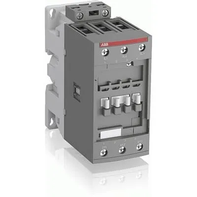
ABB 1SBL367061R1300 Block Contactor is a 3-pole device for controlling 3-phase motors up to 22 kW at 400 V AC. In fluctuating networks, control voltage drift and energy waste can trigger nuisance trips and inefficiency. This AF technology meets IEC/EN 60947-1, 60947-4-1 and UL/CSA safety standards, with CE and UKCA declarations. With a wide control voltage range and a compact block design, wiring is simplified and future expansion is straightforward. Designed for DIN rail mounting, it also supports add-on auxiliary contact blocks and a broad range of accessories, delivering scalable control for conveyors, pumps, and fans. By reducing panel energy consumption and enabling simple maintenance, it supports lower total cost of ownership over the product life cycle.
Product Information
Extended Description
1SBL367061R1300 ABB: The AF52B-30-00-13 is a 3 pole - 690 V IEC or 600 UL contactor with screw terminals, controlling motors up to 22 kW / 400 V AC (AC-3) or 40 hp / 480 V UL and switching power circuits up to 100 A (AC-1) or 80 A UL general use. Thanks to the AF technology, the contactor has a wide control voltage range (100-250 V 50/60 Hz and DC), managing large control voltage variations, reducing panel energy consumptions and ensuring distinct operations in unstable networks. Furthermore, surge protection is built-in, offering a compact solution. AF contactors have a block type design, can be easily extended with add-on auxiliary contact blocks and an additional wide range of accessories.
Minimum Order Quantity
1 piece
Customs Tariff Number
85364900
Data Sheet, Technical Information
Motor control and protection for Rolling stock application_PDF
Instructions and Manuals
Installation instructions AF(C)40(B)...96(B)-30 Contactors, CA4, CAL4, CAT4, CC4, LDC4 Accessories
Instructions and Manuals (Part 2)
Contactors and Overload relays guide
CAD Dimensional Drawing
Information - 2D and 3D files for CAD systems
Product Net Width
55 mm
Product Net Depth / Length
111 mm
Product Net Height
125.5 mm
Product Net Weight
0.95 kg
Number of Main Contacts NO
3
Number of Main Contacts NC
0
Number of Auxiliary Contacts NO
0
Number of Auxiliary Contacts NC
0
Number of Poles
3P
Standards
IEC/EN 60947-1, IEC/EN 60947-4-1, UL 60335-2-40 LZGH2 A2L, UL 60947-1, UL 60947-4-1, CSA C22.2 No. 60335-2-40 LZGH2 A2L, CSA C22.2 No. 60947-1:22, CSA C22.2 No. 60947-4-1:22, IEC 60077-1 (applicable parts), IEC 60077-2 (applicable parts), EN 50155 (applicable parts), IEC 61373, For compliance confirmation on applicable parts based on your application and combination, please consult your ABB sales representatives.
Rated Operational Voltage
Main Circuit 690 V
Rated Frequency (f)
Control Circuit 50 / 60 Hz | Main Circuit 50 / 60 Hz
Conventional Free-air Thermal Current (Ith)
acc. to IEC 60947-4-1, Open Contactors Θ = 40 °C 105 A
Rated Operational Current AC-1 (Ie)
(690 V) 40 °C 100 A | (690 V) 60 °C 80 A | (690 V) 70 °C 70 A
Rated Operational Current AC-3 (Ie)
(415 V) 60 °C 53 A | (440 V) 60 °C 53 A | (500 V) 60 °C 45 A | (690 V) 60 °C 35 A | (380 / 400 V) 60 °C 53 A | (220 / 230 / 240 V) 60 °C 53 A
Rated Operational Current AC-3e (Ie)
(415 V) 60 °C 53 A | (440 V) 60 °C 53 A | (500 V) 60 °C 45 A | (690 V) 60 °C 35 A | (380 / 400 V) 60 °C 53 A | (220 / 230 / 240 V) 60 °C 53 A
Rated Operational Current DC-1 (Ie)
(110 V) 2 Poles in Series, 40 °C 100 A | (110 V) 2 Poles in Series, 60 °C 80 A | (110 V) 2 Poles in Series, 70 °C 70 A | (110 V) 3 Poles in Series, 40 °C 100 A | (110 V) 3 Poles in Series, 60 °C 80 A | (110 V) 3 Poles in Series, 70 °C 70 A | (220 V) 3 Poles in Series, 40 °C 100 A | (220 V) 3 Poles in Series, 60 °C 80 A | (220 V) 3 Poles in Series, 70 °C 70 A | (72 V) 1-Pole, 40 °C 100 A | (72 V) 1-Pole, 60 °C 80 A | (72 V) 1-Pole, 70 °C 70 A | (72 V) 2 Poles in Series, 40 °C 100 A | (72 V) 2 Poles in Series, 60 °C 80 A | (72 V) 2 Poles in Series, 70 °C 70 A | (72 V) 3 Poles in Series, 40 °C 100 A | (72 V) 3 Poles in Series, 60 °C 80 A | (72 V) 3 Poles in Series, 70 °C 70 A
Rated Operational Current DC-3 (Ie)
(110 V) 2 Poles in Series, 40 °C 100 A | (110 V) 2 Poles in Series, 60 °C 80 A | (110 V) 2 Poles in Series, 70 °C 70 A | (110 V) 3 Poles in Series, 40 °C 100 A | (110 V) 3 Poles in Series, 60 °C 80 A | (110 V) 3 Poles in Series, 70 °C 70 A | (220 V) 3 Poles in Series, 40 °C 100 A | (220 V) 3 Poles in Series, 60 °C 80 A | (220 V) 3 Poles in Series, 70 °C 70 A | (72 V) 1-Pole, 40 °C 100 A | (72 V) 1-Pole, 60 °C 80 A | (72 V) 1-Pole, 70 °C 70 A | (72 V) 2 Poles in Series, 40 °C 100 A | (72 V) 2 Poles in Series, 60 °C 80 A | (72 V) 2 Poles in Series, 70 °C 70 A | (72 V) 3 Poles in Series, 40 °C 100 A | (72 V) 3 Poles in Series, 60 °C 80 A | (72 V) 3 Poles in Series, 70 °C 70 A
Rated Operational Current DC-5 (Ie)
(110 V) 2 Poles in Series, 40 °C 100 A | (110 V) 2 Poles in Series, 60 °C 80 A | (110 V) 2 Poles in Series, 70 °C 70 A | (110 V) 3 Poles in Series, 40 °C 100 A | (110 V) 3 Poles in Series, 60 °C 80 A | (110 V) 3 Poles in Series, 70 °C 70 A | (220 V) 3 Poles in Series, 40 °C 100 A | (220 V) 3 Poles in Series, 60 °C 80 A | (220 V) 3 Poles in Series, 70 °C 70 A | (72 V) 1-Pole, 40 °C 100 A | (72 V) 1-Pole, 60 °C 80 A | (72 V) 1-Pole, 70 °C 70 A | (72 V) 2 Poles in Series, 40 °C 100 A | (72 V) 2 Poles in Series, 60 °C 80 A | (72 V) 2 Poles in Series, 70 °C 70 A | (72 V) 3 Poles in Series, 40 °C 100 A | (72 V) 3 Poles in Series, 60 °C 80 A | (72 V) 3 Poles in Series, 70 °C 70 A
Rated Operational Power AC-3 (Pe)
(400 V) 22 kW | (415 V) 30 kW | (440 V) 30 kW | (500 V) 30 kW | (690 V) 30 kW | (380 / 400 V) 22 kW | (220 / 230 / 240 V) 15 kW
Rated Operational Power AC-3e (Pe)
(415 V) 30 kW | (440 V) 30 kW | (500 V) 30 kW | (690 V) 30 kW | (380 / 400 V) 22 kW | (220 / 230 / 240 V) 15 kW
Rated Short-time Withstand Current Low Voltage (Icw)
at 40 °C Ambient Temp, in Free Air, from a Cold State 10 s 600 A | at 40 °C Ambient Temp, in Free Air, from a Cold State 15 min 110 A | at 40 °C Ambient Temp, in Free Air, from a Cold State 1 min 250 A | at 40 °C Ambient Temp, in Free Air, from a Cold State 1 s 1000 A | at 40 °C Ambient Temp, in Free Air, from a Cold State 30 s 350 A
Maximum Breaking Capacity
cos phi=0.45 (cos phi=0.35 for Ie > 100 A) at 440 V 950 A | cos phi=0.45 (cos phi=0.35 for Ie > 100 A) at 690 V 600 A
Rated Insulation Voltage (Ui)
acc. to IEC 60947-4-1 690 V | acc. to UL/CSA 600 V
Maximum Electrical Switching Frequency
(AC-1) 600 cycles per hour | (AC-2 / AC-4) 150 cycles per hour | (AC-3) 1200 cycles per hour
Maximum Mechanical Switching Frequency
3600 cycles per hour
Rated Control Circuit Voltage (Uc)
50 Hz 100 ... 250 V | 60 Hz 100 ... 250 V | DC Operation 100 ... 250 V
Coil Consumption
Average Holding Value 50 / 60 Hz 4 V·A | Average Holding Value DC 2 W
Power Loss
at Rated Operating Conditions AC-1 per Pole 6.3 W | at Rated Operating Conditions AC-3 per Pole 1.7 W
Operate Time
Between Coil De-energization and NC Contact Closing 19 ... 105 ms | Between Coil De-energization and NO Contact Opening 17 ... 100 ms | Between Coil Energization and NC Contact Opening 38 ... 95 ms | Between Coil Energization and NO Contact Closing 42 ... 100 ms
Mounting on DIN Rail
TH35-15 (35 x 15 mm Mounting Rail) acc. to IEC 60715 | TH35-7.5 (35 x 7.5 mm Mounting Rail) acc. to IEC 60715
Mounting by Screws (not supplied)
2 x M4 or 2 x M6 screws placed diagonally
Connecting Capacity Main Circuit
Flexible with Ferrule 1/2x 4 ... 35 mm² | Flexible with Insulated Ferrule 1/2x 4 ... 35 mm² | Rigid Stranded 1/2x 6 ... 35 mm²
Connecting Capacity Control Circuit
Flexible with Ferrule 1/2x 0.75 ... 2.5 mm² | Flexible with Insulated Ferrule 1x 0.75 ... 2.5 mm² | Flexible with Insulated Ferrule 2x 0.75 ... 1.5 mm² | Rigid Solid 1/2x 1 ... 2.5 mm² | Rigid Stranded 1/2x 1 ... 2.5 mm²
Wire Stripping Length
Auxiliary Circuit 0 mm | Control Circuit 10 mm | Main Circuit 16 mm
Degree of Protection
acc. to IEC 60529, IEC 60947-1, EN 60529 Coil Terminals IP20 | acc. to IEC 60529, IEC 60947-1, EN 60529 Main Terminals IP10
Recommended Screw Driver
Pozidriv PZ
Tightening Torque
Control Circuit 1.2 N·m | Main Circuit 4 N·m
Terminal Type
Screw Terminals
Product Name
Block Contactor
Continuous Current Rating NEMA
0 A
Maximum Operating Voltage UL/CSA
Main Circuit 600 V
General Use Rating UL/CSA
(600 V AC) 80 A
Horsepower Rating UL/CSA
(120 V AC) Single Phase 3 hp | (200 ... 208 V AC) Three Phase 15 hp | (220 ... 240 V AC) Three Phase 20 hp | (240 V AC) Single Phase 10 hp | (440 ... 480 V AC) Three Phase 40 hp | (550 ... 600 V AC) Three Phase 50 hp
Connecting Capacity Main Circuit UL/CSA
Rigid Stranded 1/2x 10-2 AWG
Connecting Capacity Control Circuit UL/CSA
Rigid Solid 1/2x 18-14 AWG | Rigid Stranded 1/2x 18-14 AWG
Tightening Torque UL/CSA
Control Circuit 11 in·lb | Main Circuit 35 in·lb
Full Load Amps Motor Use
(120 V AC) Single Phase 34 A | (200 ... 208 V AC) Three Phase 48.3 A | (220 ... 240 V AC) Three Phase 54 A | (240 V AC) Single Phase 50 A | (440 ... 480 V AC) Three Phase 52 A | (550 ... 600 V AC) Three Phase 52 A
Ambient Air Temperature
Close to Contactor Fitted with Thermal O/L Relay -40 ... 70 °C | Close to Contactor without Thermal O/L Relay -40 ... 70 °C | Close to Contactor for Storage -60 ... +80 °C
Climatic Withstand
Category B according to IEC 60947-1 Annex Q
Maximum Operating Altitude Permissible
Without Derating 3000 m
Shock and Vibration Withstand acc. to IEC 61373
Category 1, Class B
Pollution Degree
3
REACH Declaration
REACH - Letter of Confirmation for block contactors, contactor relays, installation contactors, mini contactors, mini contactor relays, thermal overload relays, electronic overload relays and related accessories
RoHS Information
RoHS II declaration for block contactors, installation contactors, mini contactors, mini contactor relays, thermal overload relays, electronic overload relays and related accessories
RoHS Status
Following EU Directive 2011/65/EU and Amendment 2015/863 July 22, 2019
Toxic Substances Control Act - TSCA
Toxic Substances Control Act (TSCA) declaration for Contactors
WEEE B2C / B2B
Business To Business
WEEE Category
5. Small Equipment (No External Dimension More Than 50 cm)
ABB EcoSolutions
Yes
End Of Life Disassembling Instructions
End of life instruction AF(S)40/52/65/80/96(B)(RT) Contactors
Environmental Product Declaration - EPD
Environmental Product Declaration AF(S)40(B), AF(S)52(B), AF(S)65(B) (FR)
Sustainable Material Content in Packaging (wt. %)
FSC Recycled Paper - 94.6 %
Sustainable Material Content in Product (wt. %)
Recycled Metal - 28.2 %
A2L Certificate – UL
UL-US Certificate of Compliance AF40 ... AF96 3-pole contactors - UL 60335-2-40 Household and Similar Electrical Appliances - Safety - Part 2-40: Particular Requirements for Electrical Heat Pumps, Air-Conditioners and Dehumidifiers | UL-CA Certificate of Compliance AF40 ... AF96 3-pole contactors - CSA C22.2 No. 60335-2-40 Household and Similar Electrical Appliances - Safety - Part 2-40: Particular Requirements for Electrical Heat Pumps, Air-Conditioners and Dehumidifiers
CB Certificate
CB Certificate AF(S)40(B), (S)AF52(B), AF(S)65(B) 3 and 4-pole contactors
CCC Certificate
CQC Certificate, Contactor, AF*40-30-**-**, AF40-40-**-**, AF40-22-**-**, AF*52-30-**-**, AF52-40-**-**,AF*65-30-**-**, Made in France
Declaration of Conformity - CE
EU Declaration of Conformity AF09 ... AF38(Z)B..(K), AF40B ... AF96B 3 and 4-pole contactors
Declaration of Conformity - UKCA
UK Declaration of Conformity AF09 ... AF38(Z)B..(K), AF40B ... AF96B 3 and 4-pole contactors
UL Certificate
UL-US-L312527-1141-10303102-9 | UL-CA-L312527-4141-10303102-9
Package Level 1 Units
box 1 piece
Package Level 1 Width
150 mm
Package Level 1 Depth / Length
150 mm
Package Level 1 Height
97 mm
Package Level 1 Gross Weight
1.05 kg
Package Level 1 EAN
3471523025004
Package Level 2 Units
box 10 piece
Package Level 2 Width
250 mm
Package Level 2 Depth / Length
300 mm
Package Level 2 Height
300 mm
Package Level 2 Gross Weight
10.5 kg
Object Classification Code
Q
ETIM 7
EC000066 - Power contactor, AC switching
ETIM 8
EC000066 - Power contactor, AC switching
ETIM 9
EC000066 - Power contactor, AC switching
eClass
V11.0 : 27371003
UNSPSC
39121529
Three-pole main circuit rated for up to 690 V supports motor loads up to 22 kW at 400 V and up to 30 kW at higher voltages (AC-3). This means you can drive common industrial motors directly, simplifying protection schemes and reducing panel footprint. In applications such as conveyors, process pumps, and fans, the ABB AF contactor provides reliable switching under demanding duty cycles while keeping line-side wiring straightforward. Wide control voltage range and surge protection deliver stability in networks with voltage fluctuations. The AF technology can be driven from 100-250 V AC/50/60 Hz or DC, minimizing panel reconfiguration when power quality shifts. This reduces nuisance trips, improves uptime, and lowers maintenance costs in facilities with mixed supply voltages. Block design enables compact panel layouts; add-on auxiliary contact blocks extend NO/NC options without replacing the base unit. With screw terminals and a robust DIN rail mounting option (TH35), installation is faster and more reliable. The device also supports a broad range of accessories for custom control circuits, enhancing scalability in evolving automation projects. Low power loss per pole (6.3 W AC-1, 1.7 W AC-3) and short operate times ensure fast, predictable switching with minimal heat. Rated to withstand frequent switching (up to 1200 cycles per hour under AC-3) and mechanical life up to 3600 cycles per hour, the block contactor is suited for demanding production lines. Mounting on TH35 DIN rails and screw-terminal connections support reliable, service-friendly integration.
Get a Quick Quote for a ABB 1SBL367061R1300
Chat with us on WhatsApp - fast responses guaranteed
Need to speak with someone? We'll call you back within 2 hours during business hours
Interested in ABB 1SBL367061R1300?
Enquire Now
FAQs
The unit is designed for TH35-15 or TH35-7.5 DIN rails and also supports mounting with 2 x M4 or 2 x M6 screws diagonally. For DIN rail installation, snap the device onto the rail and ensure the coil terminals are accessible. When mounting with screws, place them diagonally as indicated and tighten to the specified torque to maintain secure electrical contact and vibration resistance.
The contactor coil accepts 100–250 V for AC, 50/60 Hz and DC operation. Coil current is supported by a holding value of 4 V·A at 50/60 Hz and 2 W in DC operation, enabling stable coil performance across fluctuating control voltages and improving energy efficiency in panel deployments.
Rated Operational Power AC-3 shows 22 kW at 400 V, 30 kW at 415–690 V, and similar values at other high voltages. This means the device can directly switch motors across a range from about 15 kW to 30 kW depending on the exact supply, simplifying motor control in diverse electrical infrastructures.
The device complies with IEC/EN 60947-1 and 60947-4-1, UL 60335-2-40 family standards, CSA equivalents, and CE/UKCA declarations. These certifications support safe integration into global installations and help ensure regulatory compliance across markets.
With wide voltage tolerance and built-in surge protection, this contactor reduces nuisance trips and energy waste, lowering maintenance costs. Its compact block design and add-on accessory capability simplify spare parts planning and expansion, delivering faster installation, easier panel wiring, and a lower total cost of ownership over the product life cycle.