ABB 1SBL381001R5111 Block Contactor - UL 60335-2-40
Part Number: 1SBL381001R5111
Quick Summary
ABB AFC contactor is a 3-pole power switch designed for AC-3 and AC-1 motor control in industrial drives. Engineers often struggle with coil voltage compatibility and wiring complexity; this model offers built-in auxiliary contact and screw terminals for straightforward, scalable control. It carries IEC/EN 60947-1, IEC/EN 60947-4-1, UL 60947-4-1, and UL 60335-2-40 LZGH2 A2L certifications, supporting global compliance and safe operation. With compact DIN rail mounting, a block contactor form factor, and extendable add-on blocks, it delivers space efficiency and easier maintenance in control panels, especially in conveyors, pumps, and fans.
Product Information
Extended Description
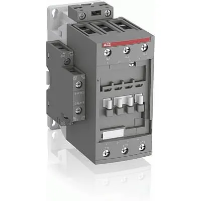
1SBL381001R5111 ABB: The AFC65-30-11-51 is a 3-pole - 690 V IEC or 600 V UL contactor with 1 N.O + 1 N.C built-in auxiliary contact and Screw terminals, mainly controlling power circuits up to 30 kW / 400 V AC (AC-3) or 50 hp / 480 V AC UL and 105 A (AC-1) or 90 A UL general use. Within the AF platform, AFC contactors offer an optimized operating time for AC controlled applications with electromagnetic coil (control voltage : 400 ... 415 V AC 50 Hz / 480 V AC 60 Hz). AFC contactors have a block type design and can be easily extended with add-on auxiliary contact blocks and a wide range of additionnal accessories.
Minimum Order Quantity
1 piece
Customs Tariff Number
85364900
Data Sheet, Technical Information
1SBC100219C0201 AFC contactors for AC control applications_Catalog PDF
Instructions and Manuals
Installation instructions AF(C)40(B)...96(B)-30 Contactors, CA4, CAL4, CAT4, CC4, LDC4 Accessories
Instructions and Manuals (Part 2)
Contactors and Overload relays guide
Product Net Width
67 mm
Product Net Depth / Length
119.5 mm
Product Net Height
111 mm
Product Net Weight
1.02 kg
Number of Main Contacts NO
3
Number of Main Contacts NC
0
Number of Auxiliary Contacts NO
1
Number of Auxiliary Contacts NC
1
Number of Poles
3P
Standards
IEC/EN 60947-1, IEC/EN 60947-4-1, UL 60947-4-1, CSA C22.2 No. 60947-4-1, UL 60335-2-40 LZGH2 A2L
Rated Operational Voltage
Main Circuit 690 V
Rated Frequency (f)
Auxiliary Circuit 50 / 60 Hz | Main Circuit 50 / 60 Hz
Conventional Free-air Thermal Current (Ith)
acc. to IEC 60947-4-1, Open Contactors Θ = 40 °C 105 A | acc. to IEC 60947-5-1, Θ = 40 °C 16 A
Rated Operational Current AC-1 (Ie)
(690 V) 40 °C 105 A | (690 V) 60 °C 90 A | (690 V) 70 °C 80 A
Rated Operational Current AC-3 (Ie)
(415 V) 60 °C 65 A | (440 V) 60 °C 65 A | (500 V) 60 °C 55 A | (690 V) 60 °C 39 A | (380 / 400 V) 60 °C 65 A | (220 / 230 / 240 V) 60 °C 65 A
Rated Operational Current AC-3e (Ie)
(415 V) 60 °C 65 A | (440 V) 60 °C 65 A | (500 V) 60 °C 55 A | (690 V) 60 °C 39 A | (380 / 400 V) 60 °C 65 A | (220 / 230 / 240 V) 60 °C 65 A
Rated Operational Current AC-15 (Ie)
(500 V) NC 2 | (500 V) 2 A | (690 V) 2 A | (24 / 127 V) 6 A | (220 / 240 V) 4 A | (400 / 440 V) 3 A
Rated Operational Current DC-13 (Ie)
(24 V) 6 A / 144 W | (48 V) 2.8 A / 134 W | (72 V) 1 A / 72 W | (110 V) 0.55 A / 60 W | (125 V) 0.55 A / 69 W | (220 V) 0.27 A / 60 W | (250 V) 0.27 A / 68 W | (400 V) 0.15 A / 60 W | (500 V) 0.13 A / 65 W | (600 V) 0.1 A / 60 W
Rated Operational Power AC-3 (Pe)
(415 V) 37 kW | (440 V) 37 kW | (500 V) 37 kW | (690 V) 37 kW | (380 / 400 V) 30 kW | (220 / 230 / 240 V) 18.5 kW
Rated Operational Power AC-3e (Pe)
(415 V) 37 kW | (440 V) 37 kW | (500 V) 37 kW | (690 V) 37 kW | (380 / 400 V) 30 kW | (220 / 230 / 240 V) 18.5 kW
Rated Operational Power AC-6b (Pe)
(400 / 415 V) 40 °C, 50 / 60 Hz 43 kvar | (400 / 415 V) 70 °C, 50 / 60 Hz 39 kvar | (400 / 415 V) 55 °C, 50 / 60 Hz 43 kvar | (500 / 550 V), 40 °C, 50 / 60 Hz 54 kvar | (500 / 550 V) 55 °C, 50 / 60 Hz 54 kvar | (500 / 550 V) 70 °C, 50 / 60 Hz 48.5 kvar | (690 V) 40 °C, 50 / 60 Hz 74 kvar | (690 V) 55 °C, 50 / 60 Hz 74 kvar | (690 V) 70 °C, 50 / 60 Hz 67 kvar
Rated Short-time Withstand Current Low Voltage (Icw)
at 40 °C Ambient Temp, in Free Air, from a Cold State 15 min 110 A | at 40 °C Ambient Temp, in Free Air, from a Cold State 1 min 250 A | at 40 °C Ambient Temp, in Free Air, from a Cold State 1 s 1000 A | at 40 °C Ambient Temp, in Free Air, from a Cold State 30 s 350 A | for 0.1 s 140 A | for 1 s 100 A
Maximum Breaking Capacity
cos phi=0.45 (cos phi=0.35 for Ie > 100 A) at 440 V 950 A | cos phi=0.45 (cos phi=0.35 for Ie > 100 A) at 690 V 600 A
Rated Insulation Voltage (Ui)
acc. to IEC 60947-4-1 and VDE 0110 (Gr. C) 690 V | acc. to UL/CSA 600 V
Rated Impulse Withstand Voltage (Uimp)
Auxiliary Circuit 6 kV
Maximum Electrical Switching Frequency
(AC-1) 600 cycles per hour | (AC-15) 1200 cycles per hour | (AC-2 / AC-4) 150 cycles per hour | (AC-3) 1200 cycles per hour | (DC-13) 900 cycles per hour
Maximum Mechanical Switching Frequency
3600 cycles per hour
Rated Control Circuit Voltage (Uc)
50 Hz 400 ... 415 V | 60 Hz 480 V
Coil Consumption
Average Holding Value 50 / 60 Hz 20 V·A | Average Pull-in Value 50 Hz 150 V·A | Average Pull-in Value 60 Hz 151 V·A
Power Loss
at Rated Operating Conditions AC-1 per Pole 7 W | at Rated Operating Conditions AC-3 per Pole 2.7 W
Operate Time
Between Coil De-energization and NC Contact Closing 6 ... 19 ms | Between Coil De-energization and NO Contact Opening 4 ... 14 ms | Between Coil Energization and NC Contact Opening 3 ... 16 ms | Between Coil Energization and NO Contact Closing 7 ... 21 ms
Mounting on DIN Rail
TH35-15 (35 x 15 mm Mounting Rail) acc. to IEC 60715 | TH35-7.5 (35 x 7.5 mm Mounting Rail) acc. to IEC 60715
Mounting by Screws (not supplied)
2 x M4 or 2 x M6 screws placed diagonally
Connecting Capacity Main Circuit
Flexible with Ferrule 1/2x 4 ... 35 mm² | Flexible with Insulated Ferrule 1/2x 4 ... 35 mm² | Rigid 1/2x 6 ... 3 5 mm² | Rigid 1/2x 6 ... 35 mm²
Connecting Capacity Auxiliary Circuit
Flexible with Ferrule 1/2x 0.75 ... 2.5 mm² | Flexible with Insulated Ferrule 1x 0.75 ... 2.5 mm² | Flexible with Insulated Ferrule 2x 0.75 ... 1.5 mm² | Rigid 1/2x 1 ... 2.5 mm²
Connecting Capacity Control Circuit
Flexible with Ferrule 1/2x 0.75 ... 2.5 mm² | Flexible with Insulated Ferrule 1x 0.75 ... 2.5 mm² | Flexible with Insulated Ferrule 2x 0.75 ... 1.5 mm² | Rigid 1/2x 1 ... 2.5 mm²
Wire Stripping Length
Control Circuit 10 mm | Main Circuit 16 mm
Degree of Protection
acc. to IEC 60529, IEC 60947-1, EN 60529 Auxiliary Terminals IP20 | acc. to IEC 60529, IEC 60947-1, EN 60529 Coil Terminals IP20 | acc. to IEC 60529, IEC 60947-1, EN 60529 Main Terminals IP10
Recommended Screw Driver
Main Circuit 6.5 | Main Circuit Slot | Control Circuit 5.5 | Control Circuit Slot
Tightening Torque
Auxiliary Circuit 1.2 N·m | Control Circuit 1.2 N·m | Main Circuit 4 N·m
Terminal Type
Screw Terminals
Product Name
Block Contactor
Maximum Operating Voltage UL/CSA
Main Circuit 600 V
General Use Rating UL/CSA
(600 V AC) 90 A
Horsepower Rating UL/CSA
(120 V AC) Single Phase 5 hp | (200 ... 208 V AC) Three Phase 20 hp | (220 ... 240 V AC) Three Phase 25 hp | (240 V AC) Single Phase 15 hp | (440 ... 480 V AC) Three Phase 50 hp | (550 ... 600 V AC) Three Phase 60 hp
Tightening Torque UL/CSA
Auxiliary Circuit 11 in·lb | Control Circuit 11 in·lb | Main Circuit 35 in·lb
Full Load Amps Motor Use
(120 V AC) Single Phase 56 A | (200 ... 208 V AC) Three Phase 62.1 A | (220 ... 240 V AC) Three Phase 68 A | (240 V AC) Single Phase 68 A | (440 ... 480 V AC) Three Phase 65 A | (550 ... 600 V AC) Three Phase 62 A
Ambient Air Temperature
Close to Contactor without Thermal O/L Relay -40 ... 70 °C | Close to Contactor for Storage -60 ... +80 °C | Near Contactor for Operation in Free Air (0.85 ... 1.1 Uc) -40 ... +60 °C | Near Contactor for Operation in Free Air (Uc) -40 ... 70 °C
Climatic Withstand
Category B according to IEC 60947-1 Annex Q
Maximum Operating Altitude Permissible
Without Derating 3000 m
Resistance to Shock acc. to IEC 60068-2-27
Closed, Shock Direction: A 25 g | Closed, Shock Direction: B1 25 g | Closed, Shock Direction: B2 15 g | Closed, Shock Direction: C1 25 g | Closed, Shock Direction: C2 25 g | Open, Shock Direction: B1 5 g
Pollution Degree
3
REACH Declaration
REACH - Letter of Confirmation for block contactors, contactor relays, installation contactors, mini contactors, mini contactor relays, thermal overload relays, electronic overload relays and related accessories
RoHS Information
RoHS II declaration for block contactors, installation contactors, mini contactors, mini contactor relays, thermal overload relays, electronic overload relays and related accessories
RoHS Status
Following EU Directive 2011/65/EU and Amendment 2015/863 July 22, 2019
Toxic Substances Control Act - TSCA
Toxic Substances Control Act (TSCA) declaration for Contactors
WEEE B2C / B2B
Business To Business
WEEE Category
5. Small Equipment (No External Dimension More Than 50 cm)
A2L Certificate – UL
UL-US Certificate of Compliance AFC40 ... AFC96 3-pole contactors - UL 60335-2-40 Household and Similar Electrical Appliances - Safety - Part 2-40: Particular Requirements for Electrical Heat Pumps, Air-Conditioners and Dehumidifiers | UL-CA Certificate of Compliance AFC40 ... AFC96 3-pole contactors - CSA C22.2 No. 60335-2-40 Household and Similar Electrical Appliances - Safety - Part 2-40: Particular Requirements for Electrical Heat Pumps, Air-Conditioners and Dehumidifiers
BV Certificate
BV_2634H36994B1
CB Certificate
CB Certificate AFC40, AFC52, AFC65 3 or 4-pole contactors
CCC Certificate
CCC Declaration of Conformity, Contactor, AF(C)40, AF52(C), AF65(C),AFC78 Made in China
Declaration of Conformity - CE
EU Declaration of Conformity AFC09..(K) ... AFC96 3-pole Contactors
Declaration of Conformity - UKCA
UK Declaration of Conformity AFC09..(K) ... AFC96 3-pole Contactors
DNV Certificate
DNV Certificate AFC09...96 3-pole & AFC09...80 4-pole contactors with screw, push-in terminals
RINA Certificate
Rina Certificate for AFC09...AFC96 3 pole and 4 pole contactors, NFC relays ,screw and spring terminals
UL Certificate
UL-CA Certificate of Compliance AFC40 ... AFC78 3-pole contactors | UL-US Certificate of Compliance AFC40 ... AFC78 3-pole contactors
Package Level 1 Units
box 1 piece
Package Level 1 Width
146.5 mm
Package Level 1 Depth / Length
96.5 mm
Package Level 1 Height
146.5 mm
Package Level 1 Gross Weight
1.14 kg
Package Level 1 EAN
3471523024533
Object Classification Code
Q
ETIM 7
EC000066 - Power contactor, AC switching
ETIM 8
EC000066 - Power contactor, AC switching
ETIM 9
EC000066 - Power contactor, AC switching
eClass
V11.0 : 27371003
UNSPSC
39121529
IDEA Granular Category Code (IGCC)
4755 >> Contactors
Feature: 3-pole design with 690 V main circuit and 400-415 V coil voltage enables robust AC-3 and AC-1 motor control. Business Impact: Supports high-load switching with reliable arc suppression and long life, reducing unplanned downtime. Application: Ideal for industrial drives up to 30 kW at 400 V AC and 50 Hz, 105 A AC-1, 65 A AC-3, in fans, pumps, and conveyors. Feature: Built-in auxiliary contact block (1 NO + 1 NC) simplifies logic and feedback. Business Impact: Improves control reliability and reduces wiring complexity for PLC interfaces. Application: Helpful for interlocking schemes and status signaling in machine panels. Feature: Screw terminals and broad conductor range (0.75–35 mm² main/aux wiring). Business Impact: Easier termination, faster installation, and better maintenance access, lowering commissioning time. Application: Suitable for rigid or flexible conductors in industrial enclosures. Feature: DIN rail mounting (TH35-15 or TH35-7.5) and block design allow easy panel integration. Business Impact: Saves panel space and enables modular expansion with add-on contact blocks. Application: Common in compact control cabinets and retrofit projects. Feature: Efficiency and thermal performance (Ith, Ie, Pe) designed for continuous operation. Business Impact: Lower energy use and thermal stress, extending device life. Application: Critical in high-cycle environments like material handling and processing lines.
Get a Quick Quote for a ABB 1SBL381001R5111
Chat with us on WhatsApp - fast responses guaranteed
Need to speak with someone? We'll call you back within 2 hours during business hours
Interested in ABB 1SBL381001R5111?
Enquire Now
FAQs
Install the 3-pole AFC65 on a TH35 rail (TH35-15 or TH35-7.5) as specified. Use 2 x M4 or M6 screws if mounting directly, and connect the main circuit with flexible or rigid conductors in the 1/2 x 4-35 mm² range. Wire the built-in NO/NC auxiliary contact to the control circuit using 0.75–2.5 mm² conductors for reliable feedback in your PLC or sequencing logic.
For AC-1 at 690 V, Ie is rated up to 105 A (40 °C). For AC-3, Ie is 65 A at 415–690 V and 65 A at 380–400 V, with Ie values adjusted to 60 °C and 70 °C as temperatures rise. Pe for AC-3 is around 37 kW at the specified voltages, and the device supports robust short-time withstand and common industrial duty cycles.
Yes. The AFC65-30-11-51 is designed for AC-3 and AC-1 control at 400–415 V (50 Hz) / 480 V (60 Hz) coil inputs and a main circuit up to 690 V. It handles up to 105 A AC-1 and 65 A AC-3, making it well-suited for motor starters in conveyors, pumps, and similar drives, with a compact footprint and add-on accessory compatibility.
The device complies with IEC/EN 60947-1 and 60947-4-1 standards, UL 60947-4-1, CSA C22.2 No. 60947-4-1, and UL 60335-2-40 LZGH2 A2L. CE and UKCA conformance are referenced in the DoC suites. These certifications support safe operation across European and North American markets and facilitate cross-border procurement.
ROI benefits come from reduced wiring complexity, faster commissioning due to built-in auxiliary contacts, and modular add-ons that minimize spare parts. The 3P design with screw terminals and DIN rail mounting improves installation efficiency, while reliable IEC/UL certifications reduce compliance risk. Over time, lower maintenance costs and fewer unscheduled outages translate to a favorable total cost of ownership.