ABB 1SBL381001R8411 Block Contactor - IEC/UL 60947
Part Number: 1SBL381001R8411
Quick Summary
Block Contactor from ABB 1SBL381001R8411 provides reliable AC power switching for motor control. Engineers often grapple with coil wear, slow operate times, and voltage mismatches that disrupt machine uptime. This device is designed to meet IEC/EN 60947-4-1, UL 60947-4-1, and CSA C22.2 certifications, with CE/UKCA declarations for global deployment. Its compact footprint, DIN-rail mounting options, and built-in auxiliary contact block deliver streamlined installation, reduced panel depth, and easier maintenance, supporting higher line efficiency without compromising safety or compliance. In short, it blends robust electrical performance with practical integration advantages for modern automation environments.
Product Information
Extended Description
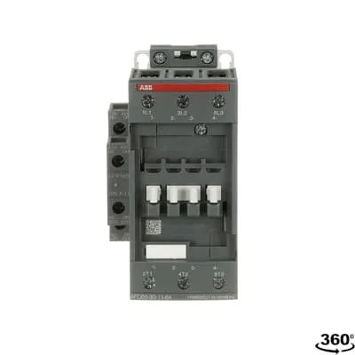
1SBL381001R8411 ABB: The AFC65-30-11-84 is a 3-pole - 690 V IEC or 600 V UL contactor with 1 N.O + 1 N.C built-in auxiliary contact and Screw terminals, mainly controlling power circuits up to 30 kW / 400 V AC (AC-3) or 50 hp / 480 V AC UL and 105 A (AC-1) or 90 A UL general use. Within the AF platform, AFC contactors offer an optimized operating time for AC controlled applications with electromagnetic coil (control voltage : 110 V AC 50 Hz / 110 ... 120 V AC 60 Hz). AFC contactors have a block type design and can be easily extended with add-on auxiliary contact blocks and a wide range of additionnal accessories.
Minimum Order Quantity
1 piece
Customs Tariff Number
85364900
Data Sheet, Technical Information
1SBC100219C0201 AFC contactors for AC control applications_Catalog PDF
Instructions and Manuals
Installation instructions AF(C)40(B)...96(B)-30 Contactors, CA4, CAL4, CAT4, CC4, LDC4 Accessories
Instructions and Manuals (Part 2)
Contactors and Overload relays guide
CAD Dimensional Drawing
Information - 2D and 3D files for CAD systems
Product Net Width
67 mm
Product Net Depth / Length
119.5 mm
Product Net Height
111 mm
Product Net Weight
1.02 kg
Number of Main Contacts NO
3
Number of Main Contacts NC
0
Number of Auxiliary Contacts NO
1
Number of Auxiliary Contacts NC
1
Number of Poles
3P
Standards
IEC/EN 60947-1, IEC/EN 60947-4-1, UL 60947-4-1, CSA C22.2 No. 60947-4-1, UL 60335-2-40 LZGH2 A2L
Rated Operational Voltage
Main Circuit 690 V
Conventional Free-air Thermal Current (Ith)
acc. to IEC 60947-4-1, Open Contactors Θ = 40 °C 105 A | acc. to IEC 60947-5-1, Θ = 40 °C 16 A
Rated Operational Current AC-1 (Ie)
(690 V) 40 °C 105 A | (690 V) 60 °C 90 A | (690 V) 70 °C 80 A
Rated Operational Current AC-3 (Ie)
(415 V) 60 °C 65 A | (440 V) 60 °C 65 A | (500 V) 60 °C 55 A | (690 V) 60 °C 39 A | (380 / 400 V) 60 °C 65 A | (220 / 230 / 240 V) 60 °C 65 A
Rated Operational Current AC-3e (Ie)
(415 V) 60 °C 65 A | (440 V) 60 °C 65 A | (500 V) 60 °C 55 A | (690 V) 60 °C 39 A | (380 / 400 V) 60 °C 65 A | (220 / 230 / 240 V) 60 °C 65 A
Rated Operational Current AC-15 (Ie)
(500 V) NC 2
Rated Operational Current DC-13 (Ie)
(24 V) 6 A / 144 W | (48 V) 2.8 A / 134 W | (72 V) 1 A / 72 W | (110 V) 0.55 A / 60 W | (125 V) 0.55 A / 69 W | (220 V) 0.27 A / 60 W | (250 V) 0.27 A / 68 W | (400 V) 0.15 A / 60 W | (500 V) 0.13 A / 65 W | (600 V) 0.1 A / 60 W
Rated Operational Power AC-3 (Pe)
(415 V) 37 kW | (440 V) 37 kW | (500 V) 37 kW | (690 V) 37 kW | (380 / 400 V) 30 kW | (220 / 230 / 240 V) 18.5 kW
Rated Operational Power AC-3e (Pe)
(415 V) 37 kW | (440 V) 37 kW | (500 V) 37 kW | (690 V) 37 kW | (380 / 400 V) 30 kW | (220 / 230 / 240 V) 18.5 kW
Rated Operational Power AC-6b (Pe)
(400 / 415 V) 40 °C, 50 / 60 Hz 43 kvar | (400 / 415 V) 70 °C, 50 / 60 Hz 39 kvar | (400 / 415 V) 55 °C, 50 / 60 Hz 43 kvar | (500 / 550 V), 40 °C, 50 / 60 Hz 54 kvar | (500 / 550 V) 55 °C, 50 / 60 Hz 54 kvar | (500 / 550 V) 70 °C, 50 / 60 Hz 48.5 kvar | (690 V) 40 °C, 50 / 60 Hz 74 kvar | (690 V) 55 °C, 50 / 60 Hz 74 kvar | (690 V) 70 °C, 50 / 60 Hz 67 kvar
Rated Short-time Withstand Current Low Voltage (Icw)
at 40 °C Ambient Temp, in Free Air, from a Cold State 15 min 110 A | at 40 °C Ambient Temp, in Free Air, from a Cold State 1 min 250 A | at 40 °C Ambient Temp, in Free Air, from a Cold State 1 s 1000 A | at 40 °C Ambient Temp, in Free Air, from a Cold State 30 s 350 A | for 0.1 s 140 A | for 1 s 100 A
Maximum Breaking Capacity
cos phi=0.45 (cos phi=0.35 for Ie > 100 A) at 440 V 950 A | cos phi=0.45 (cos phi=0.35 for Ie > 100 A) at 690 V 600 A
Rated Insulation Voltage (Ui)
acc. to IEC 60947-4-1 and VDE 0110 (Gr. C) 690 V | acc. to UL/CSA 600 V
Rated Impulse Withstand Voltage (Uimp)
Auxiliary Circuit 6 kV
Maximum Electrical Switching Frequency
(AC-1) 600 cycles per hour | (AC-15) 1200 cycles per hour | (AC-2 / AC-4) 150 cycles per hour | (AC-3) 1200 cycles per hour | (DC-13) 900 cycles per hour
Maximum Mechanical Switching Frequency
3600 cycles per hour
Rated Control Circuit Voltage (Uc)
50 Hz 110 V | 60 Hz 110 ... 120 V
Coil Consumption
Average Holding Value 50 / 60 Hz 20 V·A | Average Pull-in Value 50 Hz 150 V·A | Average Pull-in Value 60 Hz 151 V·A
Power Loss
at Rated Operating Conditions AC-1 per Pole 7 W | at Rated Operating Conditions AC-3 per Pole 2.7 W
Operate Time
Between Coil De-energization and NC Contact Closing 6 ... 19 ms | Between Coil De-energization and NO Contact Opening 4 ... 14 ms | Between Coil Energization and NC Contact Opening 3 ... 16 ms | Between Coil Energization and NO Contact Closing 7 ... 21 ms
Mounting on DIN Rail
TH35-15 (35 x 15 mm Mounting Rail) acc. to IEC 60715 | TH35-7.5 (35 x 7.5 mm Mounting Rail) acc. to IEC 60715
Mounting by Screws (not supplied)
2 x M4 or 2 x M6 screws placed diagonally
Connecting Capacity Main Circuit
Flexible with Ferrule 1/2x 4 ... 35 mm² | Flexible with Insulated Ferrule 1/2x 4 ... 35 mm² | Rigid 1/2x 6 ... 3 5 mm²
Connecting Capacity Auxiliary Circuit
Flexible with Ferrule 1/2x 0.75 ... 2.5 mm² | Flexible with Insulated Ferrule 1x 0.75 ... 2.5 mm² | Flexible with Insulated Ferrule 2x 0.75 ... 1.5 mm² | Rigid 1/2x 1 ... 2.5 mm²
Connecting Capacity Control Circuit
Flexible with Ferrule 1/2x 0.75 ... 2.5 mm² | Flexible with Insulated Ferrule 1x 0.75 ... 2.5 mm² | Flexible with Insulated Ferrule 2x 0.75 ... 1.5 mm² | Flexible with Insulated Ferrule 1x 0.75 ... 2.5 mm² | Flexible with Insulated Ferrule 2x 0.75 ... 1.5 mm² | Rigid 1/2x 1 ... 2.5 mm²
Wire Stripping Length
Control Circuit 10 mm | Main Circuit 16 mm
Degree of Protection
acc. to IEC 60529, IEC 60947-1, EN 60529 Auxiliary Terminals IP20 | acc. to IEC 60529, IEC 60947-1, EN 60529 Coil Terminals IP20 | acc. to IEC 60529, IEC 60947-1, EN 60529 Main Terminals IP10
Recommended Screw Driver
Main Circuit 6.5 | Main Circuit Slot | Control Circuit 5.5 | Control Circuit Slot
Tightening Torque
Auxiliary Circuit 1.2 N·m | Control Circuit 1.2 N·m | Main Circuit 4 N·m
Terminal Type
Screw Terminals
Product Name
Block Contactor
Maximum Operating Voltage UL/CSA
Main Circuit 600 V
General Use Rating UL/CSA
(600 V AC) 90 A
Horsepower Rating UL/CSA
(120 V AC) Single Phase 5 hp | (200 ... 208 V AC) Three Phase 20 hp | (220 ... 240 V AC) Three Phase 25 hp | (240 V AC) Single Phase 15 hp | (440 ... 480 V AC) Three Phase 50 hp | (550 ... 600 V AC) Three Phase 60 hp
Tightening Torque UL/CSA
Auxiliary Circuit 11 in·lb | Control Circuit 11 in·lb | Main Circuit 35 in·lb
Full Load Amps Motor Use
(120 V AC) Single Phase 56 A | (200 ... 208 V AC) Three Phase 62.1 A | (220 ... 240 V AC) Three Phase 68 A | (240 V AC) Single Phase 68 A | (440 ... 480 V AC) Three Phase 65 A | (550 ... 600 V AC) Three Phase 62 A
Ambient Air Temperature
Close to Contactor without Thermal O/L Relay -40 ... 70 °C | Close to Contactor for Storage -60 ... +80 °C
Climatic Withstand
Category B according to IEC 60947-1 Annex Q
Maximum Operating Altitude Permissible
Without Derating 3000 m
Resistance to Shock acc. to IEC 60068-2-27
Closed, Shock Direction: A 25 g | Closed, Shock Direction: B1 25 g | Closed, Shock Direction: B2 15 g | Closed, Shock Direction: C1 25 g | Closed, Shock Direction: C2 25 g | Open, Shock Direction: B1 5 g
Pollution Degree
3
Conflict Minerals Reporting Template (CMRT)
CMRT - Conflict Minerals Reporting Template
REACH Declaration
REACH - Letter of Confirmation for block contactors, contactor relays, installation contactors, mini contactors, mini contactor relays, thermal overload relays, electronic overload relays and related accessories
RoHS Information
RoHS II declaration for block contactors, installation contactors, mini contactors, mini contactor relays, thermal overload relays, electronic overload relays and related accessories
RoHS Status
Following EU Directive 2011/65/EU and Amendment 2015/863 July 22, 2019
Toxic Substances Control Act - TSCA
Toxic Substances Control Act (TSCA) declaration for Contactors
WEEE B2C / B2B
Business To Business
WEEE Category
5. Small Equipment (No External Dimension More Than 50 cm)
A2L Certificate – UL
UL-US Certificate of Compliance AFC40 ... AFC96 3-pole contactors - UL 60335-2-40 Household and Similar Electrical Appliances - Safety - Part 2-40: Particular Requirements for Electrical Heat Pumps, Air-Conditioners and Dehumidifiers | UL-CA Certificate of Compliance AFC40 ... AFC96 3-pole contactors - CSA C22.2 No. 60335-2-40 Household and Similar Electrical Appliances - Safety - Part 2-40: Particular Requirements for Electrical Heat Pumps, Air-Conditioners and Dehumidifiers
BV Certificate
BV_2634H36994B1
CB Certificate
CB Certificate AFC40, AFC52, AFC65 3 or 4-pole contactors
CCC Certificate
CCC Declaration of Conformity, Contactor, AF(C)40, AF52(C), AF65(C),AFC78 Made in China
CQC Certificate
CQC Certificate, Contactor, AF40, AF52, AF65, AFC40, AFC52, AFC65, Made in China
Declaration of Conformity - CE
EU Declaration of Conformity AFC09..(K) ... AFC96 3-pole Contactors
Declaration of Conformity - UKCA
UK Declaration of Conformity AFC09..(K) ... AFC96 3-pole Contactors
DNV Certificate
DNV Certificate AFC09...96 3-pole & AFC09...80 4-pole contactors with screw, push-in terminals
RINA Certificate
Rina Certificate for AFC09...AFC96 3 pole and 4 pole contactors, NFC relays ,screw and spring terminals
UL Certificate
UL-CA Certificate of Compliance AFC40 ... AFC78 3-pole contactors | UL-US Certificate of Compliance AFC40 ... AFC78 3-pole contactors
Package Level 1 Units
box 1 piece
Package Level 1 Width
146.5 mm
Package Level 1 Depth / Length
96.5 mm
Package Level 1 Height
146.5 mm
Package Level 1 Gross Weight
1.14 kg
Package Level 1 EAN
3471523018983
Package Level 3 Units
240 piece
Object Classification Code
Q
ETIM 7
EC000066 - Power contactor, AC switching
ETIM 8
EC000066 - Power contactor, AC switching
ETIM 9
EC000066 - Power contactor, AC switching
eClass
V11.0 : 27371003
UNSPSC
39121529
IDEA Granular Category Code (IGCC)
4758 >> Iec Contactors
Feature: 3-pole main contactor with 1 NO auxiliary and 1 NC auxiliary contact; Business Impact: Enables reliable control interlocks and status feedback while minimizing panel wiring complexity; Application: Motor control and starter circuits up to 37 kW at higher voltages. Feature: Coil voltage of 110 V AC at 50 Hz or 110–120 V AC at 60 Hz; Business Impact: Simplifies control system integration across regional power standards and reduces the need for adapters; Application: Direct control from standard 110 V control circuits. Feature: Screw terminals for main and auxiliary circuits; Business Impact: Improves wiring reliability and allows flexible conductor sizing (4–35 mm² main, 0.75–2.5 mm² auxiliary/control); Application: Field wiring in compact control panels. Feature: DIN rail mounting TH35-15 or TH35-7.5; Business Impact: Fast, tool-free installation with reliable retention and easy replacement; Application: Modular panels with standardized mounting rails. Feature: Compact dimensions (67 mm width, 111 mm height, 119.5 mm depth) and 1.02 kg weight; Business Impact: Saves panel space and reduces total installed cost; Application: Space-constrained automation cabinets. Feature: IP20/IP10 protection on terminals and IP20 for coil/aux circuits; Business Impact: Enhanced ingress protection suitable for standard control environments; Application: Standard factory automation spaces. Feature: Rated operational currents and switching performance (Ie AC-1 up to 105 A, Ie AC-3 up to 65 A at 415 V/690 V variants); Business Impact: Clear, predictable motor starting and reduced risk during startup; Application: AC-1 and AC-3 control of motors and conveyors. Feature: Low power loss and fast operate times (coil pull-in ~150 V·A, hold ~20 V·A; operate times 4–21 ms); Business Impact: Lower energy consumption and faster switching improves process control and reduces wear; Application: High-speed switching in automated lines.
Get a Quick Quote for a ABB 1SBL381001R8411
Chat with us on WhatsApp - fast responses guaranteed
Need to speak with someone? We'll call you back within 2 hours during business hours
Interested in ABB 1SBL381001R8411?
Enquire Now
FAQs
This ABB contactor is designed for DIN rail mounting on TH35-15 or TH35-7.5 rails. Install on the rail, then secure using the included mounting provisions. Conductor connections use screw terminals for main and auxiliary circuits, and ensure torque values are observed (Main 4 N·m, Auxiliary 1.2 N·m, Control 1.2 N·m) to maintain reliable contacts and long service life.
Main contacts: 3 NO. Auxiliary: 1 NO + 1 NC. For AC-3 at 690 V, Ie is 39 A and P_e is 37 kW; for AC-1 at 690 V, Ie is up to 105 A depending on temperature. This combination supports standard motor starting and control circuits with integrated feedback for interlocks and sequencing.
Yes. The coil is rated at 110 V AC for 50 Hz or 110–120 V AC for 60 Hz, aligning with widely used control systems in North America and parts of Europe. This minimizes the need for voltage converters and reduces coil mismatch risks during start-up sequences.
The device complies with IEC/EN 60947-4-1 and UL 60947-4-1, with CSA reference and CE/UKCA declarations. Additional certifications in the data sheet include various UL/CSA, BV, CB, CCC, CQC and DNV references, supporting global deployment across automotive, food and general manufacturing sectors.
For AC-3 operation at 690 V, the unit delivers up to 37 kW with Ie around 39 A. It excels in motor control applications such as pumps, conveyors and fans where reliable switching, fast operate times, and compact installation are critical, while maintaining robust thermal performance and safe operation