ABB 1SBL381001R8611 Block Contactor - UL/CSA Certified
Part Number: 1SBL381001R8611
Quick Summary
ABB 1SBL381001R8611 Block Contactor provides reliable AC control for motor starters in industrial automation. Engineers often face downtime from undersized starters and complex wiring; this device simplifies installation and improves line reliability. Certified to IEC/EN 60947-4-1, UL 60335-2-40, CSA C22.2 No. 60947-4-1, and CE, it also features IP20 auxiliary and IP10 main terminal protection for harsh environments. Designed to streamline panel design, it offers DIN rail mounting and screw-terminal connections, enabling fast installation and reliable long-term operation.
Product Information
Extended Description
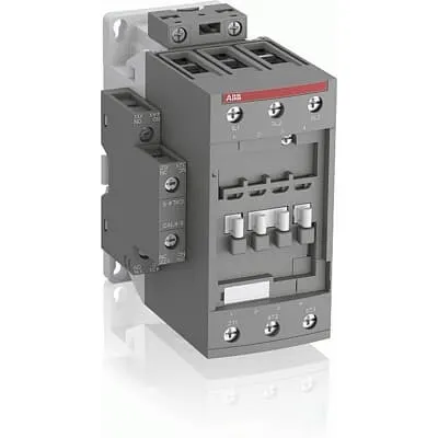
1SBL381001R8611 ABB: The AFC65-30-11-86 is a 3-pole - 690 V IEC or 600 V UL contactor with 1 N.O + 1 N.C built-in auxiliary contact and Screw terminals, mainly controlling power circuits up to 30 kW / 400 V AC (AC-3) or 50 hp / 480 V AC UL and 105 A (AC-1) or 90 A UL general use. Within the AF platform, AFC contactors offer an optimized operating time for AC controlled applications with electromagnetic coil (control voltage : 400 ... 415 V AC 50 Hz / 415 ... 440 V AC 60 Hz). AFC contactors have a block type design and can be easily extended with add-on auxiliary contact blocks and a wide range of additionnal accessories.
Minimum Order Quantity
1 piece
Customs Tariff Number
85364900
Data Sheet, Technical Information
1SBC100219C0201 AFC contactors for AC control applications_Catalog PDF
Instructions and Manuals
Installation instructions AF(C)40(B)...96(B)-30 Contactors, CA4, CAL4, CAT4, CC4, LDC4 Accessories
Instructions and Manuals (Part 2)
Contactors and Overload relays guide
Product Net Width
67 mm
Product Net Depth / Length
119.5 mm
Product Net Height
111 mm
Product Net Weight
1.02 kg
Number of Main Contacts NO
3
Number of Main Contacts NC
0
Number of Auxiliary Contacts NO
1
Number of Auxiliary Contacts NC
1
Number of Poles
3P
Standards
IEC/EN 60947-1, IEC/EN 60947-4-1, UL 60947-4-1, CSA C22.2 No. 60947-4-1, UL 60335-2-40 LZGH2 A2L
Rated Operational Voltage
Main Circuit 690 V
Rated Frequency (f)
Auxiliary Circuit 50 / 60 Hz | Main Circuit 50 / 60 Hz
Conventional Free-air Thermal Current (Ith)
acc. to IEC 60947-4-1, Open Contactors Θ = 40 °C 105 A | acc. to IEC 60947-5-1, Θ = 40 °C 16 A
Rated Operational Current AC-1 (Ie)
(690 V) 40 °C 105 A | (690 V) 60 °C 90 A | (690 V) 70 °C 80 A
Rated Operational Current AC-3 (Ie)
(415 V) 60 °C 65 A | (440 V) 60 °C 65 A | (500 V) 60 °C 55 A | (690 V) 60 °C 39 A | (380 / 400 V) 60 °C 65 A | (220 / 230 / 240 V) 60 °C 65 A
Rated Operational Current AC-3e (Ie)
(415 V) 60 °C 65 A | (440 V) 60 °C 65 A | (500 V) 60 °C 55 A | (690 V) 60 °C 39 A | (380 / 400 V) 60 °C 65 A | (220 / 230 / 240 V) 60 °C 65 A
Rated Operational Current AC-15 (Ie)
(500 V) NC 2 | (500 V) 2 A | (690 V) 2 A | (24 / 127 V) 6 A | (220 / 240 V) 4 A | (400 / 440 V) 3 A
Rated Operational Current DC-13 (Ie)
(24 V) 6 A / 144 W | (48 V) 2.8 A / 134 W | (72 V) 1 A / 72 W | (110 V) 0.55 A / 60 W | (125 V) 0.55 A / 69 W | (220 V) 0.27 A / 60 W | (250 V) 0.27 A / 68 W | (400 V) 0.15 A / 60 W | (500 V) 0.13 A / 65 W | (600 V) 0.1 A / 60 W
Rated Operational Power AC-3 (Pe)
(415 V) 37 kW | (440 V) 37 kW | (500 V) 37 kW | (690 V) 37 kW | (380 / 400 V) 30 kW | (220 / 230 / 240 V) 18.5 kW
Rated Operational Power AC-3e (Pe)
(415 V) 37 kW | (440 V) 37 kW | (500 V) 37 kW | (690 V) 37 kW | (380 / 400 V) 30 kW | (220 / 230 / 240 V) 18.5 kW
Rated Operational Power AC-6b (Pe)
(400 / 415 V) 40 °C, 50 / 60 Hz 43 kvar | (400 / 415 V) 70 °C, 50 / 60 Hz 39 kvar | (400 / 415 V) 55 °C, 50 / 60 Hz 43 kvar | (500 / 550 V), 40 °C, 50 / 60 Hz 54 kvar | (500 / 550 V) 55 °C, 50 / 60 Hz 54 kvar | (500 / 550 V) 70 °C, 50 / 60 Hz 48.5 kvar | (690 V) 40 °C, 50 / 60 Hz 74 kvar | (690 V) 55 °C, 50 / 60 Hz 74 kvar | (690 V) 70 °C, 50 / 60 Hz 67 kvar
Rated Short-time Withstand Current Low Voltage (Icw)
at 40 °C Ambient Temp, in Free Air, from a Cold State 15 min 110 A | at 40 °C Ambient Temp, in Free Air, from a Cold State 1 min 250 A | at 40 °C Ambient Temp, in Free Air, from a Cold State 1 s 1000 A | at 40 °C Ambient Temp, in Free Air, from a Cold State 30 s 350 A | for 0.1 s 140 A | for 1 s 100 A
Maximum Breaking Capacity
cos phi=0.45 (cos phi=0.35 for Ie > 100 A) at 440 V 950 A | cos phi=0.45 (cos phi=0.35 for Ie > 100 A) at 690 V 600 A
Rated Insulation Voltage (Ui)
acc. to IEC 60947-4-1 and VDE 0110 (Gr. C) 690 V | acc. to UL/CSA 600 V
Rated Impulse Withstand Voltage (Uimp)
Auxiliary Circuit 6 kV
Maximum Electrical Switching Frequency
(AC-1) 600 cycles per hour | (AC-15) 1200 cycles per hour | (AC-2 / AC-4) 150 cycles per hour | (AC-3) 1200 cycles per hour | (DC-13) 900 cycles per hour
Maximum Mechanical Switching Frequency
3600 cycles per hour
Rated Control Circuit Voltage (Uc)
50 Hz 400 ... 415 V | 60 Hz 415 ... 440 V
Coil Consumption
Average Holding Value 50 / 60 Hz 20 V·A | Average Pull-in Value 50 Hz 150 V·A | Average Pull-in Value 60 Hz 151 V·A
Power Loss
at Rated Operating Conditions AC-1 per Pole 7 W | at Rated Operating Conditions AC-3 per Pole 2.7 W
Operate Time
Between Coil De-energization and NC Contact Closing 6 ... 19 ms | Between Coil De-energization and NO Contact Opening 4 ... 14 ms | Between Coil Energization and NC Contact Opening 3 ... 16 ms | Between Coil Energization and NO Contact Closing 7 ... 21 ms
Mounting on DIN Rail
TH35-15 (35 x 15 mm Mounting Rail) acc. to IEC 60715 | TH35-7.5 (35 x 7.5 mm Mounting Rail) acc. to IEC 60715
Mounting by Screws (not supplied)
2 x M4 or 2 x M6 screws placed diagonally
Connecting Capacity Main Circuit
Flexible with Ferrule 1/2x 4 ... 35 mm² | Flexible with Insulated Ferrule 1/2x 4 ... 35 mm² | Rigid 1/2x 6 ... 3 5 mm² | Rigid 1/2x 6 ... 35 mm²
Connecting Capacity Auxiliary Circuit
Flexible with Ferrule 1/2x 0.75 ... 2.5 mm² | Flexible with Insulated Ferrule 1x 0.75 ... 2.5 mm² | Flexible with Insulated Ferrule 2x 0.75 ... 1.5 mm² | Rigid 1/2x 1 ... 2.5 mm²
Connecting Capacity Control Circuit
Flexible with Ferrule 1/2x 0.75 ... 2.5 mm² | Flexible with Insulated Ferrule 1x 0.75 ... 2.5 mm² | Flexible with Insulated Ferrule 2x 0.75 ... 1.5 mm² | Rigid 1/2x 1 ... 2.5 mm²
Wire Stripping Length
Control Circuit 10 mm | Main Circuit 16 mm
Degree of Protection
acc. to IEC 60529, IEC 60947-1, EN 60529 Auxiliary Terminals IP20 | acc. to IEC 60529, IEC 60947-1, EN 60529 Coil Terminals IP20 | acc. to IEC 60529, IEC 60947-1, EN 60529 Main Terminals IP10
Recommended Screw Driver
Main Circuit 6.5 | Main Circuit Slot | Control Circuit 5.5 | Control Circuit Slot
Tightening Torque
Auxiliary Circuit 1.2 N·m | Control Circuit 1.2 N·m | Main Circuit 4 N·m
Terminal Type
Screw Terminals
Product Name
Block Contactor
Maximum Operating Voltage UL/CSA
Main Circuit 600 V
General Use Rating UL/CSA
(600 V AC) 90 A
Horsepower Rating UL/CSA
(120 V AC) Single Phase 5 hp | (200 ... 208 V AC) Three Phase 20 hp | (220 ... 240 V AC) Three Phase 25 hp | (240 V AC) Single Phase 15 hp | (440 ... 480 V AC) Three Phase 50 hp | (550 ... 600 V AC) Three Phase 60 hp
Tightening Torque UL/CSA
Auxiliary Circuit 11 in·lb | Control Circuit 11 in·lb | Main Circuit 35 in·lb
Full Load Amps Motor Use
(120 V AC) Single Phase 56 A | (200 ... 208 V AC) Three Phase 62.1 A | (220 ... 240 V AC) Three Phase 68 A | (240 V AC) Single Phase 68 A | (440 ... 480 V AC) Three Phase 65 A | (550 ... 600 V AC) Three Phase 62 A
Ambient Air Temperature
Close to Contactor without Thermal O/L Relay -40 ... 70 °C | Close to Contactor for Storage -60 ... +80 °C | Near Contactor for Operation in Free Air (0.85 ... 1.1 Uc) -40 ... +60 °C | Near Contactor for Operation in Free Air (Uc) -40 ... 70 °C
Climatic Withstand
Category B according to IEC 60947-1 Annex Q
Maximum Operating Altitude Permissible
Without Derating 3000 m
Resistance to Shock acc. to IEC 60068-2-27
Closed, Shock Direction: A 25 g | Closed, Shock Direction: B1 25 g | Closed, Shock Direction: B2 15 g | Closed, Shock Direction: C1 25 g | Closed, Shock Direction: C2 25 g | Open, Shock Direction: B1 5 g
Pollution Degree
3
REACH Declaration
REACH - Letter of Confirmation for block contactors, contactor relays, installation contactors, mini contactors, mini contactor relays, thermal overload relays, electronic overload relays and related accessories
RoHS Information
RoHS II declaration for block contactors, installation contactors, mini contactors, mini contactor relays, thermal overload relays, electronic overload relays and related accessories
RoHS Status
Following EU Directive 2011/65/EU and Amendment 2015/863 July 22, 2019
Toxic Substances Control Act - TSCA
Toxic Substances Control Act (TSCA) declaration for Contactors
WEEE B2C / B2B
Business To Business
WEEE Category
5. Small Equipment (No External Dimension More Than 50 cm)
A2L Certificate – UL
UL-US Certificate of Compliance AFC40 ... AFC96 3-pole contactors - UL 60335-2-40 Household and Similar Electrical Appliances - Safety - Part 2-40: Particular Requirements for Electrical Heat Pumps, Air-Conditioners and Dehumidifiers | UL-CA Certificate of Compliance AFC40 ... AFC96 3-pole contactors - CSA C22.2 No. 60335-2-40 Household and Similar Electrical Appliances - Safety - Part 2-40: Particular Requirements for Electrical Heat Pumps, Air-Conditioners and Dehumidifiers
BV Certificate
BV_2634H36994B1
CB Certificate
CB Certificate AFC40, AFC52, AFC65 3 or 4-pole contactors
CCC Certificate
CCC Declaration of Conformity, Contactor, AF(C)40, AF52(C), AF65(C),AFC78 Made in China
Declaration of Conformity - CE
EU Declaration of Conformity AFC09..(K) ... AFC96 3-pole Contactors
Declaration of Conformity - UKCA
UK Declaration of Conformity AFC09..(K) ... AFC96 3-pole Contactors
DNV Certificate
DNV Certificate AFC09...96 3-pole & AFC09...80 4-pole contactors with screw, push-in terminals
RINA Certificate
Rina Certificate for AFC09...AFC96 3 pole and 4 pole contactors, NFC relays ,screw and spring terminals
UL Certificate
UL-CA Certificate of Compliance AFC40 ... AFC78 3-pole contactors | UL-US Certificate of Compliance AFC40 ... AFC78 3-pole contactors
Package Level 1 Units
box 1 piece
Package Level 1 Width
146.5 mm
Package Level 1 Depth / Length
96.5 mm
Package Level 1 Height
146.5 mm
Package Level 1 Gross Weight
1.14 kg
Package Level 1 EAN
3471523023475
Object Classification Code
Q
ETIM 7
EC000066 - Power contactor, AC switching
ETIM 8
EC000066 - Power contactor, AC switching
ETIM 9
EC000066 - Power contactor, AC switching
eClass
V11.0 : 27371003
UNSPSC
39121529
IDEA Granular Category Code (IGCC)
4755 >> Contactors
Three-pole block design with a built-in 1 NO + 1 NC auxiliary contact simplifies control circuits, reducing wiring complexity and panel depth while offering straightforward expansion with add-on auxiliary blocks. This translates to faster panel assembly and easier maintenance in motor-control cabinets for pumps and conveyors. Coil voltage compatibility covers 50 Hz 400–415 V and 60 Hz 415–440 V, enabling global installations without separate coil variants. Coil consumption values of approximately 150 VA pull-in and 151 VA hold at 60 Hz support predictable control power budgeting and safer, steadier operation. Ie AC-3 is 65 A at 415/440 V and 39 A at 690 V, with Pe rated around 37 kW across typical line voltages, enabling reliable motor starts up to several tens of kilowatts. The device supports rapid switching with a maximum mechanical rate of 3600 cycles per hour and up to 1200 cycles per hour for AC-3 electrical switching, giving you resilient performance in demanding cycles. Durable, compact design mounts on standard DIN rails (TH35-15 or TH35-7.5) and accepts both ferrule and rigid conductors via screw terminals. With precise torque specs—main circuit 4 N·m, auxiliary/control circuits 1.2 N·m, and compatible conductor sizes up to 35 mm² for main conductors—installation is reliable and repeatable. Compliance and protection features include RoHS/REACH, WEEE B2B categorization, and multiple safety certifications (IEC/EN, UL/CSA, CE). IP ratings provide protection for auxiliary and coil terminals (IP20) and main terminals (IP10), helping equipment survive harsh industrial environments.
Get a Quick Quote for a ABB 1SBL381001R8611
Chat with us on WhatsApp - fast responses guaranteed
Need to speak with someone? We'll call you back within 2 hours during business hours
Interested in ABB 1SBL381001R8611?
Enquire Now
FAQs
The device is designed for DIN rail mounting on TH35 rails, with additional screw mounting suitability. It supports TH35-15 and TH35-7.5 rails and can be fastened using 2 x M4 or 2 x M6 screws placed diagonally for secure fixed installation, ensuring reliable operation in crowded control panels.
Coil control voltage is 50 Hz 400–415 V or 60 Hz 415–440 V, enabling operation across regional power standards. Coil consumption includes an average holding value around 20 VA and pull-in values near 150–151 VA, which supports predictable control power budgeting and stable coil operation.
Rated Operational Current AC-3 (Ie) is 65 A at 415/440 V, 60 °C rated, and 39 A at 690 V. This makes the contactor suitable for motors with substantial starting currents while maintaining safe thermal performance in typical industrial installations.
The product complies with IEC/EN 60947-1 and IEC/EN 60947-4-1, UL 60947-4-1, CSA C22.2 No. 60947-4-1, and UL 60335-2-40. CE declarations and RoHS/REACH compliance are also provided, supporting global deployment in regulated industrial environments.
Ideal for motor control in pumps, fans, conveyors, and small to mid-size drives, this 3P contactor delivers reliable AC-3 switching up to 37 kW, with a compact footprint and easy expansion via auxiliary blocks. Businesses can expect reduced downtime, faster panel assembly, and lower maintenance costs due to robust DIN-rail mounting and durable screw-terminal connections.