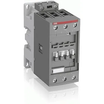
ABB AF65-30-00-11 Contactor - 690V UL/CSA
Part Number: 1SBL387001R1100
Quick Summary
ABB AF65-30-00-11 Contactor enables three-pole motor control in demanding industrial applications such as pumps and conveyors. Fluctuating control voltages and unstable networks often cause nuisance trips and energy waste, which AF technology helps prevent with a wide voltage range (24–60 VAC/VDC) and built-in surge protection. It carries IEC/EN 60947-1, IEC/EN 60947-4-1, UL 60335-2-40 and CSA certifications, with CE and UKCA marks for global deployments. The compact 55 mm wide block design supports easy DIN rail mounting and straightforward expansion using add-on auxiliary contact blocks, reducing panel space and inventory. Overall, this contactor delivers reliable motor control, improved panel density, and lower lifecycle costs in harsh industrial environments.
Product Information
Extended Description
1SBL387001R1100 ABB: The AF65-30-00-11 is a 3 pole - 690 V IEC or 600 UL contactor with screw terminals, controlling motors up to 30 kW / 400 V AC (AC-3) or 50 hp / 480 V UL and switching power circuits up to 105 A (AC-1) or 90 A UL general use. Thanks to the AF technology, the contactor has a wide control voltage range (24-60 V 50/60 Hz and 20-60 V DC), managing large control voltage variations, reducing panel energy consumptions and ensuring distinct operations in unstable networks. Furthermore, surge protection is built-in, offering a compact solution. AF contactors have a block type design, can be easily extended with add-on auxiliary contact blocks and an additional wide range of accessories.
Minimum Order Quantity
1 piece
Data Sheet, Technical Information
1SBC100214C0202 - Main catalog Motor protection and control Manual motor starters, contactors and overload relays (PDF) - Edition 2024
Instructions and Manuals
Installation instructions AF(C)40(B)...96(B)-30 Contactors, CA4, CAL4, CAT4, CC4, LDC4 Accessories
Instructions and Manuals (Part 2)
Contactors and Overload relays guide
CAD Dimensional Drawing
Information - 2D and 3D files for CAD systems
Product Net Width
55 mm
Product Net Depth / Length
111 mm
Product Net Height
125.5 mm
Product Net Weight
0.97 kg
Number of Main Contacts NO
3
Number of Main Contacts NC
0
Number of Auxiliary Contacts NO
0
Number of Auxiliary Contacts NC
0
Number of Poles
3P
Standards
IEC/EN 60947-1, IEC/EN 60947-4-1, UL 60335-2-40 LZGH2 A2L, UL 60947-1, UL 60947-4-1, CSA C22.2 No. 60335-2-40 LZGH2 A2L, CSA C22.2 No. 60947-1:22, CSA C22.2 No. 60947-4-1:22
Rated Operational Voltage
Main Circuit 690 V
Rated Frequency (f)
Control Circuit 50 / 60 Hz | Main Circuit 50 / 60 Hz
Conventional Free-air Thermal Current (Ith)
acc. to IEC 60947-4-1, Open Contactors Θ = 40 °C 105 A
Rated Operational Current AC-1 (Ie)
(690 V) 40 °C 105 A | (690 V) 60 °C 90 A | (690 V) 70 °C 80 A
Rated Operational Current AC-3 (Ie)
(415 V) 60 °C 65 A | (440 V) 60 °C 65 A | (500 V) 60 °C 55 A | (690 V) 60 °C 39 A | (380 / 400 V) 60 °C 65 A | (220 / 230 / 240 V) 60 °C 65 A
Rated Operational Current AC-3e (Ie)
(415 V) 60 °C 65 A | (440 V) 60 °C 65 A | (500 V) 60 °C 55 A | (690 V) 60 °C 39 A | (380 / 400 V) 60 °C 65 A | (220 / 230 / 240 V) 60 °C 65 A
Rated Operational Current DC-1 (Ie)
(110 V) 2 Poles in Series, 40 °C 105 A | (110 V) 2 Poles in Series, 60 °C 90 A | (110 V) 2 Poles in Series, 70 °C 80 A | (110 V) 3 Poles in Series, 40 °C 105 A | (110 V) 3 Poles in Series, 60 °C 90 A | (110 V) 3 Poles in Series, 70 °C 80 A | (220 V) 3 Poles in Series, 40 °C 105 A | (220 V) 3 Poles in Series, 60 °C 90 A | (220 V) 3 Poles in Series, 70 °C 80 A | (72 V) 1-Pole, 40 °C 105 A | (72 V) 1-Pole, 60 °C 90 A | (72 V) 1-Pole, 70 °C 80 A | (72 V) 2 Poles in Series, 40 °C 105 A | (72 V) 2 Poles in Series, 60 °C 90 A | (72 V) 2 Poles in Series, 70 °C 80 A | (72 V) 3 Poles in Series, 40 °C 105 A | (72 V) 3 Poles in Series, 60 °C 90 A | (72 V) 3 Poles in Series, 70 °C 80 A
Rated Operational Current DC-3 (Ie)
(110 V) 2 Poles in Series, 40 °C 105 A | (110 V) 2 Poles in Series, 60 °C 90 A | (110 V) 2 Poles in Series, 70 °C 80 A | (110 V) 3 Poles in Series, 40 °C 105 A | (110 V) 3 Poles in Series, 60 °C 90 A | (110 V) 3 Poles in Series, 70 °C 80 A | (220 V) 3 Poles in Series, 40 °C 105 A | (220 V) 3 Poles in Series, 60 °C 90 A | (220 V) 3 Poles in Series, 70 °C 80 A | (72 V) 1-Pole, 40 °C 105 A | (72 V) 1-Pole, 60 °C 90 A | (72 V) 1-Pole, 70 °C 80 A | (72 V) 2 Poles in Series, 40 °C 105 A | (72 V) 2 Poles in Series, 60 °C 90 A | (72 V) 2 Poles in Series, 70 °C 80 A | (72 V) 3 Poles in Series, 40 °C 105 A | (72 V) 3 Poles in Series, 60 °C 90 A | (72 V) 3 Poles in Series, 70 °C 80 A
Rated Operational Current DC-5 (Ie)
(110 V) 2 Poles in Series, 40 °C 105 A | (110 V) 2 Poles in Series, 60 °C 90 A | (110 V) 2 Poles in Series, 70 °C 80 A | (110 V) 3 Poles in Series, 40 °C 105 A | (110 V) 3 Poles in Series, 60 °C 90 A | (110 V) 3 Poles in Series, 70 °C 80 A | (220 V) 3 Poles in Series, 40 °C 105 A | (220 V) 3 Poles in Series, 60 °C 90 A | (220 V) 3 Poles in Series, 70 °C 80 A | (72 V) 1-Pole, 40 °C 105 A | (72 V) 1-Pole, 60 °C 90 A | (72 V) 1-Pole, 70 °C 80 A | (72 V) 2 Poles in Series, 40 °C 105 A | (72 V) 2 Poles in Series, 60 °C 90 A | (72 V) 2 Poles in Series, 70 °C 80 A | (72 V) 3 Poles in Series, 40 °C 105 A | (72 V) 3 Poles in Series, 60 °C 90 A | (72 V) 3 Poles in Series, 70 °C 80 A
Rated Operational Power AC-3 (Pe)
(400 V) 30 kW | (415 V) 37 kW | (440 V) 37 kW | (500 V) 37 kW | (690 V) 37 kW | (380 / 400 V) 30 kW | (220 / 230 / 240 V) 18.5 kW
Rated Operational Power AC-3e (Pe)
(415 V) 37 kW | (440 V) 37 kW | (500 V) 37 kW | (690 V) 37 kW | (380 / 400 V) 30 kW | (220 / 230 / 240 V) 18.5 kW
Rated Short-time Withstand Current Low Voltage (Icw)
at 40 °C Ambient Temp, in Free Air, from a Cold State 10 s 600 A | at 40 °C Ambient Temp, in Free Air, from a Cold State 15 min 110 A | at 40 °C Ambient Temp, in Free Air, from a Cold State 1 min 250 A | at 40 °C Ambient Temp, in Free Air, from a Cold State 1 s 1000 A | at 40 °C Ambient Temp, in Free Air, from a Cold State 30 s 350 A
Maximum Breaking Capacity
cos phi=0.45 (cos phi=0.35 for Ie > 100 A) at 440 V 950 A | cos phi=0.45 (cos phi=0.35 for Ie > 100 A) at 690 V 600 A
Rated Insulation Voltage (Ui)
acc. to IEC 60947-4-1 690 V | acc. to UL/CSA 600 V
Rated Impulse Withstand Voltage (Uimp)
6 kV
Maximum Electrical Switching Frequency
(AC-1) 600 cycles per hour | (AC-2 / AC-4) 150 cycles per hour | (AC-3) 1200 cycles per hour
Maximum Mechanical Switching Frequency
3600 cycles per hour
Rated Control Circuit Voltage (Uc)
50 Hz 24 ... 60 V | 60 Hz 24 ... 60 V | DC Operation 20 ... 60 V
Coil Consumption
Average Holding Value 50 / 60 Hz 4 V·A | Average Holding Value 50 Hz 4 V·A | Average Holding Value 60 Hz 4 V·A | Average Holding Value DC 2 W | Average Holding Value, from Warm State 2 W
Power Loss
at Rated Operating Conditions AC-1 per Pole 7 W | at Rated Operating Conditions AC-3 per Pole 2.7 W
Operate Time
Between Coil De-energization and NC Contact Closing 19 ... 105 ms | Between Coil De-energization and NO Contact Opening 17 ... 100 ms | Between Coil Energization and NC Contact Opening 38 ... 95 ms | Between Coil Energization and NO Contact Closing 42 ... 100 ms
Mounting on DIN Rail
TH35-15 (35 x 15 mm Mounting Rail) acc. to IEC 60715 | TH35-7.5 (35 x 7.5 mm Mounting Rail) acc. to IEC 60715
Mounting by Screws (not supplied)
2 x M4 or 2 x M6 screws placed diagonally
Connecting Capacity Main Circuit
Flexible with Ferrule 1/2x 4 ... 35 mm² | Flexible with Insulated Ferrule 1/2x 4 ... 35 mm² | Rigid Stranded 1/2x 6 ... 35 mm²
Connecting Capacity Control Circuit
Flexible with Ferrule 1/2x 0.75 ... 2.5 mm² | Flexible with Insulated Ferrule 1x 0.75 ... 2.5 mm² | Flexible with Insulated Ferrule 2x 0.75 ... 1.5 mm² | Rigid Solid 1/2x 1 ... 2.5 mm² | Rigid Stranded 1/2x 1 ... 2.5 mm²
Wire Stripping Length
Control Circuit 10 mm | Main Circuit 16 mm
Degree of Protection
acc. to IEC 60529, IEC 60947-1, EN 60529 Coil Terminals IP20 | acc. to IEC 60529, IEC 60947-1, EN 60529 Main Terminals IP10
Recommended Screw Driver
Pozidriv PZ
Tightening Torque
Control Circuit 1.2 N·m | Main Circuit 4 N·m
Terminal Type
Screw Terminals
Product Name
Block Contactor
Maximum Operating Voltage UL/CSA
Main Circuit 600 V
General Use Rating UL/CSA
(600 V AC) 90 A
Horsepower Rating UL/CSA
(120 V AC) Single Phase 5 hp | (200 ... 208 V AC) Three Phase 20 hp | (220 ... 240 V AC) Three Phase 25 hp | (240 V AC) Single Phase 15 hp | (440 ... 480 V AC) Three Phase 50 hp | (550 ... 600 V AC) Three Phase 60 hp
Connecting Capacity Main Circuit UL/CSA
Rigid Stranded 1/2x 10-2 AWG
Connecting Capacity Control Circuit UL/CSA
Rigid Solid 1/2x 18-14 AWG | Rigid Stranded 1/2x 18-14 AWG
Tightening Torque UL/CSA
Control Circuit 11 in·lb | Main Circuit 35 in·lb
Full Load Amps Motor Use
(120 V AC) Single Phase 56 A | (200 ... 208 V AC) Three Phase 62.1 A | (220 ... 240 V AC) Three Phase 68 A | (240 V AC) Single Phase 68 A | (440 ... 480 V AC) Three Phase 65 A | (550 ... 600 V AC) Three Phase 62 A
Ambient Air Temperature
Close to Contactor Fitted with Thermal O/L Relay -40 ... 70 °C | Close to Contactor without Thermal O/L Relay -40 ... 70 °C | Close to Contactor for Storage -60 ... +80 °C
Climatic Withstand
Category B according to IEC 60947-1 Annex Q
Maximum Operating Altitude Permissible
Without Derating 3000 m
Resistance to Shock acc. to IEC 60068-2-27
Closed, Shock Direction: A 25 g | Closed, Shock Direction: B1 25 g | Closed, Shock Direction: B2 15 g | Closed, Shock Direction: C1 25 g | Closed, Shock Direction: C2 25 g | Open, Shock Direction: B1 5 g
Resistance to Vibrations
3g Closed Position & 3g Open Position 5 ... 300 Hz
Pollution Degree
3
Conflict Minerals Reporting Template (CMRT)
CMRT - Conflict Minerals Reporting Template
REACH Declaration
REACH - Letter of Confirmation for block contactors, contactor relays, installation contactors, mini contactors, mini contactor relays, thermal overload relays, electronic overload relays and related accessories
RoHS Information
RoHS II declaration for block contactors, installation contactors, mini contactors, mini contactor relays, thermal overload relays, electronic overload relays and related accessories
RoHS Status
Following EU Directive 2011/65/EU and Amendment 2015/863 July 22, 2019
SCIP
027369a1-d0c4-4022-9c69-6abbc771eef0 France (FR)
Simplified SCIP
35535b00-3559-41dd-ba43-4f10e10316a4 Czech Republic (CZ) | eab94b80-8a80-493c-9b92-a73ba592b112 Bulgaria (BG) | dcb8ee84-7120-4a48-bd69-16f72ce443f5 Sweden (SE) | cce3ac24-2a61-4686-beaf-6178155141b3 Poland (PL) | d42934c1-6c5f-4ef4-9ee5-58c3d526687e France (FR) | a689c760-751b-4be4-9f82-9176d1b466bb Sweden (SE) | c7c9c97f-5bca-4709-9586-d42c0311f03f Germany (DE) | 278fd4bb-b087-4d60-a153-2d45942126de Germany (DE) | 19e79a30-187e-4fda-8fea-3e3963ed76bf Hungary (HU) | 782a537f-1341-4633-abd5-e826adedf2b8 Germany (DE) | d3d144f1-0adf-4d10-a04e-b2831a583ba1 Finland (FI) | 6dd99915-339b-4386-8a21-21cfda9179e8 Belgium (BE) | c9344780-ca4c-42bc-952d-9ef02731fd68 Germany (DE) | ca62b1a6-c5e6-4254-bbb4-b9377bac6bdc Poland (PL) | d49929ae-44fe-47fe-8264-37dd194ef189 Netherlands (NL) | 6b5ee982-c1a5-4508-88cb-aac7acc86fcd Hungary (HU) | a0f4e357-48ca-4b01-8198-2410812bfbff Estonia (EE) | fcd03632-5a3f-470f-9b24-1d81b191430f Greece (GR) | 31a286b7-17ad-4cbe-9ff8-b9686a9c51df Portugal (PT) | e6e14e05-3bfe-4fac-8dde-d71994626c82 Spain (ES) | 7bdeae90-e0e6-44e4-b876-bafc74500ced Belgium (BE) | 29e8a32f-4c66-4174-b78a-63ba758f264e Poland (PL) | 554d77c8-5237-45c6-8a9e-e6406cd77688 Norway (NO) | 9ebeae57-c6a8-4e04-89a3-103511571c08 Italy (IT) | 5ad226d6-8b3d-417b-919a-610bbad4ed52 Denmark (DK) | fa566f5f-f2e2-4378-8324-6f1e0688d760 Germany (DE) | f7e65b7c-a14e-401f-9592-548b5c76fe12 Croatia (HR)
Toxic Substances Control Act - TSCA
Toxic Substances Control Act (TSCA) declaration for Contactors
WEEE B2C / B2B
Business To Business
WEEE Category
5. Small Equipment (No External Dimension More Than 50 cm)
ABB EcoSolutions
Yes
End Of Life Disassembling Instructions
End of life instruction AF(S)40/52/65/80/96(B)(RT) Contactors
Environmental Product Declaration - EPD
Environmental Product Declaration AF40, AF52, AF65 (CN) | Environmental Product Declaration AF(S)40(B), AF(S)52(B), AF(S)65(B) (FR)
Sustainable Material Content in Packaging (wt. %)
FSC Recycled Paper - 94.6 %
Sustainable Material Content in Product (wt. %)
Recycled Metal - 28.2 %
A2L Certificate – UL
UL-US Certificate of Compliance AF40 ... AF96 3-pole contactors - UL 60335-2-40 Household and Similar Electrical Appliances - Safety - Part 2-40: Particular Requirements for Electrical Heat Pumps, Air-Conditioners and Dehumidifiers | UL-CA Certificate of Compliance AF40 ... AF96 3-pole contactors - CSA C22.2 No. 60335-2-40 Household and Similar Electrical Appliances - Safety - Part 2-40: Particular Requirements for Electrical Heat Pumps, Air-Conditioners and Dehumidifiers
ABS Certificate
ABS Certificate, AF(S)09 to AF(S)96 contactors, NF contactor relays and CA4, CC4, CAL4, CAT4 auxiliary contact blocks, TEF4 electronic timers
BV Certificate
BV_2634H36994B1
CB Certificate
CB Certificate AF(S)40(B), (S)AF52(B), AF(S)65(B) 3 and 4-pole contactors
CCC Certificate
CQC Certificate, Contactor, AF*40-30-**-**, AF40-40-**-**, AF40-22-**-**, AF*52-30-**-**, AF52-40-**-**,AF*65-30-**-**, Made in France
CQC Certificate
CQC Certificate, Contactor, AF*40-30-**-**, AF40-40-**-**, AF40-22-**-**, AF*52-30-**-**, AF52-40-**-**,AF*65-30-**-**, Made in France | CQC Certificate, Contactor, AF40, AF52, AF65, AFC40, AFC52, AFC65, Made in China
Declaration of Conformity - CCC
CCC Declaration of Conformity, Contactor, AF*40-30-**-**, AF40-40-**-**, AF40-22-**-**, AF*52-30-**-**, AF52-40-**-**,AF*65-30-**-**, Made in France | CCC Declaration of Conformity, Contactor, AF(C)40, AF52(C), AF65(C),AFC78 Made in China
Declaration of Conformity - CE
EU Declaration of Conformity AF09... AF96-30-.., AF09...38(Z)-30..K 3-pole Contactors
Declaration of Conformity - UKCA
UK Declaration of Conformity AF09... AF96-30-.., AF09...38(Z)-30..K 3-pole Contactors
DNV Certificate
DNV Certificate AF(S)09...96 3-pole & AF09...80 4-pole contactors with screw, spring, push-in terminals
KC Certificate
KC Certificate AF65 3-pole Contactors
LR Certificate
LRS Certificate AF(S)09..(K) ... AF96 3 and 4-pole contactors and CA(L)4..(K), CAT4, CC4 auxiliary contact blocks
RINA Certificate
Rina Certificate for AF09...AF96 contactors, NF contactor relays and accessories, screw and spring terminals
RMRS Certificate
RMRS Certificate AF(S)09(S)...AF(S)38 3-pole and 4-pole, AF(S)40..96 3-pole contactors with screw, push-in and spring terminals
UL Certificate
UL-US-L312527-1141-10303102-9 | UL-CA-L312527-4141-10303102-9
UL Listing Card
UL_E312527
Package Level 1 Units
box 1 piece
Package Level 1 Width
150 mm
Package Level 1 Depth / Length
150 mm
Package Level 1 Height
97 mm
Package Level 1 Gross Weight
1.07 kg
Package Level 1 EAN
3471523132610
Package Level 2 Units
box 10 piece
Package Level 2 Width
250 mm
Package Level 2 Depth / Length
300 mm
Package Level 2 Height
300 mm
Package Level 2 Gross Weight
10.7 kg
Package Level 3 Units
240 piece
Object Classification Code
Q
ETIM 7
EC000066 - Power contactor, AC switching
ETIM 8
EC000066 - Power contactor, AC switching
ETIM 9
EC000066 - Power contactor, AC switching
eClass
V11.0 : 27371003
UNSPSC
39121529
IDEA Granular Category Code (IGCC)
4758 >> Iec Contactors
E-Number (Finland)
3707046
E-Number (Sweden)
3210042
Feature AF65-30-00-11 leverages AF technology to tolerate wide control voltage variations, delivering a stable motor start and reducing energy waste. Business Impact: fewer nuisance trips and lower panel energy consumption, especially in networks with fluctuating voltages. Application: 3P motors up to 30 kW / 400 V AC (AC-3) and 50 hp/480 UL, ideal for fans, pumps and conveyors. Feature Built-in surge protection and compact block design. Business Impact: enhanced protection with fewer external components and a smaller footprint, enabling higher panel density. Application: motor protection circuits in limited-space MCCs and control panels. Feature 3P, 690 V main circuit with high I_e ratings. Business Impact: supports heavy-duty switching with reliable endurance; reduces total system parts by covering both AC-1 and AC-3 duties in one device. Application: industrial drive applications requiring robust, code-compliant contactors. Feature Coil voltage range 24–60 V AC/DC and coil power management. Business Impact: versatile control compatibility with varied control networks and lower standby energy; Application: integration with PLCs, relays and fieldbus interfaces. Feature Screw terminals and flexible conductor connections (1/2x 4–35 mm² main; 0.75–2.5 mm² control). Business Impact: faster wiring, easier maintenance, and reliable, repeatable torque performance. Application: field installation in automation cabinets and control housings. Feature Mounting on TH35 DIN rails or with screws. Business Impact: quick installation and modular expansion in existing control panels; Application: new MCCs and retrofits in industrial environments. Feature Compliance and certifications (IEC/EN 60947-1, 60947-4-1; UL/CSA; CE/UKCA). Business Impact: simplifies regulatory approvals and global deployments; Application: international machinery and equipment projects.
Get a Quick Quote for a ABB 1SBL387001R1100
Chat with us on WhatsApp - fast responses guaranteed
Need to speak with someone? We'll call you back within 2 hours during business hours
Interested in ABB 1SBL387001R1100?
Enquire Now
FAQs
The AF65-30-00-11 supports DIN rail mounting with TH35-15 or TH35-7.5 profiles and can be mounted using two screws (M4 or M6) placed diagonally. Use screw terminals for the main circuit and ensure proper wire sizes: main circuit 1/2x 4–35 mm², control circuit 0.75–2.5 mm². Tighten main terminals to 4 N·m and control terminals to 1.2 N·m. This ensures reliable performance in compact MCCs.
At 690V, the Rated Operational Current for AC-1 is 105 A at 40°C, 90 A at 60°C, and 80 A at 70°C. For AC-3 at 690V, the rating is 39 A at 60°C. These values indicate robust switching capability for motor loads (AC-3) and general use (AC-1) in high-temperature environments typical of industrial settings.
Yes. The coil accepts a wide DC control voltage range of 20–60 V, complementing 24–60 V AC operation. This enables direct interfacing with DC control circuits or PLC outputs, while keeping coil power consumption low (2 W DC holding, 4 V·A typical). The device maintains reliable operation across mixed control networks commonly found in automated lines.
The AF65-30-00-11 complies with IEC 60947-1 and 60947-4-1, and carries UL 60335-2-40 and CSA listings. It also features CE and UKCA marks, addressing global regulatory requirements. Additional certifications include UL/CSA electrical safety and multiple third-party attestations to support compliance in diverse markets.
Add-on auxiliary contact blocks allow you to tailor the control circuit to exact needs without replacing the base unit, reducing spare parts and maintenance complexity. This modularity speeds commissioning, simplifies diagnostics, and lowers long-term ownership costs by enabling scalable control logic for evolving automation requirements.