ABB 1SBL387001R1122 Block Contactor - IEC 60947-4-1 690V
Part Number: 1SBL387001R1122
Quick Summary
Block Contactor is a robust motor control device used to start and stop large motors in industrial automation and machine-building. In practice, engineers face voltage variability and nuisance trips when supply conditions swing, requiring a device with wide control voltage tolerance. This ABB AF65-based model carries IEC/EN 60947-1 and IEC/EN 60947-4-1 approvals, plus UL/CSA documentation and CE/UKCA declarations for global compliance. Its compact block design is easy to integrate into existing panels, while the pre-mounted auxiliary contacts streamline wiring. By combining surge protection with a versatile control voltage range, it helps reduce energy waste, simplify maintenance, and improve overall panel reliability in demanding environments.
Product Information
Extended Description
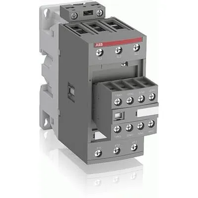
1SBL387001R1122 ABB: The AF65-30-22-11 is a 3 pole - 690 V IEC or 600 UL contactor with pre-mounted auxiliary contacts and screw terminals, controlling motors up to 30 kW / 400 V AC (AC-3) or 50 hp / 480 V UL and switching power circuits up to 105 A (AC-1) or 90 A UL general use. Thanks to the AF technology, the contactor has a wide control voltage range (24-60 V 50/60 Hz and 20-60 V DC), managing large control voltage variations, reducing panel energy consumptions and ensuring distinct operations in unstable networks. Furthermore, surge protection is built-in, offering a compact solution. AF contactors have a block type design, can be easily extended with add-on auxiliary contact blocks and an additional wide range of accessories.
Minimum Order Quantity
1 piece
Data Sheet, Technical Information
1SBC100214C0202 - Main catalog Motor protection and control Manual motor starters, contactors and overload relays (PDF) - Edition 2024
Instructions and Manuals
Installation instructions AF(C)40(B)...96(B)-30 Contactors, CA4, CAL4, CAT4, CC4, LDC4 Accessories
Instructions and Manuals (Part 2)
Contactors and Overload relays guide
CAD Dimensional Drawing
Information - 2D and 3D files for CAD systems
Product Net Width
55 mm
Product Net Depth / Length
144 mm
Product Net Height
125.5 mm
Product Net Weight
1.02 kg
Number of Main Contacts NO
3
Number of Main Contacts NC
0
Number of Auxiliary Contacts NO
2
Number of Auxiliary Contacts NC
2
Number of Poles
3P
Standards
IEC/EN 60947-1, IEC/EN 60947-4-1, UL 60335-2-40 LZGH2 A2L, UL 60947-1, UL 60947-4-1, CSA C22.2 No. 60335-2-40 LZGH2 A2L, CSA C22.2 No. 60947-1:22, CSA C22.2 No. 60947-4-1:22
Rated Operational Voltage
Auxiliary Circuit 690 V | Main Circuit 690 V
Rated Frequency (f)
Auxiliary Circuit 50 / 60 Hz | Control Circuit 50 / 60 Hz | Main Circuit 50 / 60 Hz
Conventional Free-air Thermal Current (Ith)
acc. to IEC 60947-4-1, Open Contactors Θ = 40 °C 105 A | acc. to IEC 60947-5-1, Θ = 40 °C 16 A
Rated Operational Current AC-1 (Ie)
(690 V) 40 °C 105 A | (690 V) 60 °C 90 A | (690 V) 70 °C 80 A
Rated Operational Current AC-3 (Ie)
(415 V) 60 °C 65 A | (440 V) 60 °C 65 A | (500 V) 60 °C 55 A | (690 V) 60 °C 39 A | (380 / 400 V) 60 °C 65 A | (220 / 230 / 240 V) 60 °C 65 A
Rated Operational Current AC-3e (Ie)
(415 V) 60 °C 65 A | (440 V) 60 °C 65 A | (500 V) 60 °C 55 A | (690 V) 60 °C 39 A | (380 / 400 V) 60 °C 65 A | (220 / 230 / 240 V) 60 °C 65 A
Rated Operational Current AC-15 (Ie)
(500 V) 2 A | (690 V) 2 A | (24 / 127 V) 6 A | (220 / 240 V) 4 A | (400 / 440 V) 3 A
Rated Operational Current DC-1 (Ie)
(110 V) 2 Poles in Series, 40 °C 105 A | (110 V) 2 Poles in Series, 60 °C 90 A | (110 V) 2 Poles in Series, 70 °C 80 A | (110 V) 3 Poles in Series, 40 °C 105 A | (110 V) 3 Poles in Series, 60 °C 90 A | (110 V) 3 Poles in Series, 70 °C 80 A | (220 V) 3 Poles in Series, 40 °C 105 A | (220 V) 3 Poles in Series, 60 °C 90 A | (220 V) 3 Poles in Series, 70 °C 80 A | (72 V) 1-Pole, 40 °C 105 A | (72 V) 1-Pole, 60 °C 90 A | (72 V) 1-Pole, 70 °C 80 A | (72 V) 2 Poles in Series, 40 °C 105 A | (72 V) 2 Poles in Series, 60 °C 90 A | (72 V) 2 Poles in Series, 70 °C 80 A | (72 V) 3 Poles in Series, 40 °C 105 A | (72 V) 3 Poles in Series, 60 °C 90 A | (72 V) 3 Poles in Series, 70 °C 80 A
Rated Operational Current DC-3 (Ie)
(110 V) 2 Poles in Series, 40 °C 105 A | (110 V) 2 Poles in Series, 60 °C 90 A | (110 V) 2 Poles in Series, 70 °C 80 A | (110 V) 3 Poles in Series, 40 °C 105 A | (110 V) 3 Poles in Series, 60 °C 90 A | (110 V) 3 Poles in Series, 70 °C 80 A | (220 V) 3 Poles in Series, 40 °C 105 A | (220 V) 3 Poles in Series, 60 °C 90 A | (220 V) 3 Poles in Series, 70 °C 80 A | (72 V) 1-Pole, 40 °C 105 A | (72 V) 1-Pole, 60 °C 90 A | (72 V) 1-Pole, 70 °C 80 A | (72 V) 2 Poles in Series, 40 °C 105 A | (72 V) 2 Poles in Series, 60 °C 90 A | (72 V) 2 Poles in Series, 70 °C 80 A | (72 V) 3 Poles in Series, 40 °C 105 A | (72 V) 3 Poles in Series, 60 °C 90 A | (72 V) 3 Poles in Series, 70 °C 80 A
Rated Operational Current DC-5 (Ie)
(110 V) 2 Poles in Series, 40 °C 105 A | (110 V) 2 Poles in Series, 60 °C 90 A | (110 V) 2 Poles in Series, 70 °C 80 A | (110 V) 3 Poles in Series, 40 °C 105 A | (110 V) 3 Poles in Series, 60 °C 90 A | (110 V) 3 Poles in Series, 70 °C 80 A | (220 V) 3 Poles in Series, 40 °C 105 A | (220 V) 3 Poles in Series, 60 °C 90 A | (220 V) 3 Poles in Series, 70 °C 80 A | (72 V) 1-Pole, 40 °C 105 A | (72 V) 1-Pole, 60 °C 90 A | (72 V) 1-Pole, 70 °C 80 A | (72 V) 2 Poles in Series, 40 °C 105 A | (72 V) 2 Poles in Series, 60 °C 90 A | (72 V) 2 Poles in Series, 70 °C 80 A | (72 V) 3 Poles in Series, 40 °C 105 A | (72 V) 3 Poles in Series, 60 °C 90 A | (72 V) 3 Poles in Series, 70 °C 80 A
Rated Operational Current DC-13 (Ie)
(24 V) 6 A / 144 W | (48 V) 2.8 A / 134 W | (72 V) 1 A / 72 W | (110 V) 0.55 A / 60 W | (125 V) 0.55 A / 69 W | (220 V) 0.27 A / 60 W | (250 V) 0.27 A / 68 W | (400 V) 0.15 A / 60 W | (500 V) 0.13 A / 65 W | (600 V) 0.1 A / 60 W
Rated Operational Power AC-3 (Pe)
(400 V) 30 kW | (415 V) 37 kW | (440 V) 37 kW | (500 V) 37 kW | (690 V) 37 kW | (380 / 400 V) 30 kW | (220 / 230 / 240 V) 18.5 kW
Rated Operational Power AC-3e (Pe)
(415 V) 37 kW | (440 V) 37 kW | (500 V) 37 kW | (690 V) 37 kW | (380 / 400 V) 30 kW | (220 / 230 / 240 V) 18.5 kW
Rated Short-time Withstand Current Low Voltage (Icw)
at 40 °C Ambient Temp, in Free Air, from a Cold State 10 s 600 A | at 40 °C Ambient Temp, in Free Air, from a Cold State 15 min 110 A | at 40 °C Ambient Temp, in Free Air, from a Cold State 1 min 250 A | at 40 °C Ambient Temp, in Free Air, from a Cold State 1 s 1000 A | at 40 °C Ambient Temp, in Free Air, from a Cold State 30 s 350 A | for 0.1 s 140 A | for 1 s 100 A
Maximum Breaking Capacity
cos phi=0.45 (cos phi=0.35 for Ie > 100 A) at 440 V 950 A | cos phi=0.45 (cos phi=0.35 for Ie > 100 A) at 690 V 600 A
Rated Insulation Voltage (Ui)
acc. to IEC 60947-4-1 690 V | acc. to IEC 60947-5-1 690 V | acc. to UL/CSA 600 V
Rated Impulse Withstand Voltage (Uimp)
6 kV
Maximum Electrical Switching Frequency
(AC-1) 600 cycles per hour | (AC-15) 1200 cycles per hour | (AC-2 / AC-4) 150 cycles per hour | (AC-3) 1200 cycles per hour | (DC-13) 900 cycles per hour
Maximum Mechanical Switching Frequency
3600 cycles per hour
Rated Control Circuit Voltage (Uc)
50 Hz 24 ... 60 V | 60 Hz 24 ... 60 V | DC Operation 20 ... 60 V
Power Loss
at 6 A per Pole 0.1 W | at Rated Operating Conditions AC-1 per Pole 7 W | at Rated Operating Conditions AC-3 per Pole 2.7 W
Operate Time
Between Coil De-energization and NC Contact Closing 19 ... 105 ms | Between Coil De-energization and NO Contact Opening 17 ... 100 ms | Between Coil Energization and NC Contact Opening 38 ... 95 ms | Between Coil Energization and NO Contact Closing 42 ... 100 ms
Mounting on DIN Rail
TH35-15 (35 x 15 mm Mounting Rail) acc. to IEC 60715 | TH35-7.5 (35 x 7.5 mm Mounting Rail) acc. to IEC 60715
Mounting by Screws (not supplied)
2 x M4 or 2 x M6 screws placed diagonally
Connecting Capacity Main Circuit
Flexible with Ferrule 1/2x 4 ... 35 mm² | Flexible with Insulated Ferrule 1/2x 4 ... 35 mm² | Rigid Stranded 1/2x 6 ... 35 mm²
Connecting Capacity Auxiliary Circuit
Flexible with Ferrule 1/2x 0.75 ... 2.5 mm² | Flexible with Insulated Ferrule 2x 0.75 ... 1.5 mm² | Flexible with Insulated Ferrule 1x 0.75 ... 2.5 mm² | Rigid 1/2x 1 ... 2.5 mm²
Connecting Capacity Control Circuit
Flexible with Ferrule 1/2x 0.75 ... 2.5 mm² | Flexible with Insulated Ferrule 1x 0.75 ... 2.5 mm² | Flexible with Insulated Ferrule 2x 0.75 ... 1.5 mm² | Rigid Solid 1/2x 1 ... 2.5 mm² | Rigid Stranded 1/2x 1 ... 2.5 mm²
Wire Stripping Length
Auxiliary Circuit 10 mm | Control Circuit 10 mm | Main Circuit 16 mm
Degree of Protection
acc. to IEC 60529, IEC 60947-1, EN 60529 Auxiliary Terminals IP20 | acc. to IEC 60529, IEC 60947-1, EN 60529 Coil Terminals IP20 | acc. to IEC 60529, IEC 60947-1, EN 60529 Main Terminals IP10
Tightening Torque
Auxiliary Circuit 1.2 N·m | Control Circuit 1.2 N·m | Main Circuit 4 N·m
Terminal Type
Screw Terminals
Product Name
Block Contactor
Maximum Operating Voltage UL/CSA
Main Circuit 600 V
General Use Rating UL/CSA
(600 V AC) 90 A
Horsepower Rating UL/CSA
(120 V AC) Single Phase 5 hp | (200 ... 208 V AC) Three Phase 20 hp | (220 ... 240 V AC) Three Phase 25 hp | (240 V AC) Single Phase 15 hp | (440 ... 480 V AC) Three Phase 50 hp | (550 ... 600 V AC) Three Phase 60 hp
Connecting Capacity Main Circuit UL/CSA
Rigid Stranded 1/2x 10-2 AWG
Connecting Capacity Control Circuit UL/CSA
Rigid Solid 1/2x 18-14 AWG | Rigid Stranded 1/2x 18-14 AWG
Tightening Torque UL/CSA
Auxiliary Circuit 11 in·lb | Control Circuit 11 in·lb | Main Circuit 35 in·lb
Full Load Amps Motor Use
(120 V AC) Single Phase 56 A | (200 ... 208 V AC) Three Phase 62.1 A | (220 ... 240 V AC) Three Phase 68 A | (240 V AC) Single Phase 68 A | (440 ... 480 V AC) Three Phase 65 A | (550 ... 600 V AC) Three Phase 62 A
Ambient Air Temperature
Close to Contactor Fitted with Thermal O/L Relay -40 ... 70 °C | Close to Contactor without Thermal O/L Relay -40 ... 70 °C | Close to Contactor for Storage -60 ... +80 °C
Climatic Withstand
Category B according to IEC 60947-1 Annex Q
Maximum Operating Altitude Permissible
Without Derating 3000 m
Resistance to Shock acc. to IEC 60068-2-27
Closed, Shock Direction: A 25 g | Closed, Shock Direction: B1 25 g | Closed, Shock Direction: B2 15 g | Closed, Shock Direction: C1 25 g | Closed, Shock Direction: C2 25 g | Open, Shock Direction: B1 5 g
Resistance to Vibrations
3g Closed Position & 3g Open Position 5 ... 300 Hz
Pollution Degree
3
Conflict Minerals Reporting Template (CMRT)
CMRT - Conflict Minerals Reporting Template
REACH Declaration
REACH - Letter of Confirmation for block contactors, contactor relays, installation contactors, mini contactors, mini contactor relays, thermal overload relays, electronic overload relays and related accessories
RoHS Information
RoHS II declaration for block contactors, installation contactors, mini contactors, mini contactor relays, thermal overload relays, electronic overload relays and related accessories
RoHS Status
Following EU Directive 2011/65/EU and Amendment 2015/863 July 22, 2019
Toxic Substances Control Act - TSCA
Toxic Substances Control Act (TSCA) declaration for Contactors
WEEE B2C / B2B
Business To Business
WEEE Category
5. Small Equipment (No External Dimension More Than 50 cm)
ABB EcoSolutions
Yes
End Of Life Disassembling Instructions
End of life instruction AF(S)40/52/65/80/96(B)(RT) Contactors
Environmental Product Declaration - EPD
Environmental Product Declaration AF40, AF52, AF65 (CN) | Environmental Product Declaration AF(S)40(B), AF(S)52(B), AF(S)65(B) (FR)
Sustainable Material Content in Packaging (wt. %)
FSC Recycled Paper - 94.6 %
Sustainable Material Content in Product (wt. %)
Recycled Metal - 28.2 %
A2L Certificate – UL
UL-US Certificate of Compliance AF40 ... AF96 3-pole contactors - UL 60335-2-40 Household and Similar Electrical Appliances - Safety - Part 2-40: Particular Requirements for Electrical Heat Pumps, Air-Conditioners and Dehumidifiers | UL-CA Certificate of Compliance AF40 ... AF96 3-pole contactors - CSA C22.2 No. 60335-2-40 Household and Similar Electrical Appliances - Safety - Part 2-40: Particular Requirements for Electrical Heat Pumps, Air-Conditioners and Dehumidifiers
ABS Certificate
ABS Certificate, AF(S)09 to AF(S)96 contactors, NF contactor relays and CA4, CC4, CAL4, CAT4 auxiliary contact blocks, TEF4 electronic timers
BV Certificate
BV_2634H36994B1
CB Certificate
CB Certificate AF(S)40(B), (S)AF52(B), AF(S)65(B) 3 and 4-pole contactors
CCC Certificate
CQC Certificate, Contactor, AF*40-30-**-**, AF40-40-**-**, AF40-22-**-**, AF*52-30-**-**, AF52-40-**-**,AF*65-30-**-**, Made in France
CQC Certificate
CQC Certificate, Contactor, AF*40-30-**-**, AF40-40-**-**, AF40-22-**-**, AF*52-30-**-**, AF52-40-**-**,AF*65-30-**-**, Made in France | CQC Certificate, Contactor, AF40, AF52, AF65, AFC40, AFC52, AFC65, Made in China
Declaration of Conformity - CCC
CCC Declaration of Conformity, Contactor, AF*40-30-**-**, AF40-40-**-**, AF40-22-**-**, AF*52-30-**-**, AF52-40-**-**,AF*65-30-**-**, Made in France | CCC Declaration of Conformity, Contactor, AF(C)40, AF52(C), AF65(C),AFC78 Made in China
Declaration of Conformity - CE
EU Declaration of Conformity AF09... AF96-30-.., AF09...38(Z)-30..K 3-pole Contactors
Declaration of Conformity - UKCA
UK Declaration of Conformity AF09... AF96-30-.., AF09...38(Z)-30..K 3-pole Contactors
DNV Certificate
DNV Certificate AF(S)09...96 3-pole & AF09...80 4-pole contactors with screw, spring, push-in terminals
KC Certificate
KC Certificate AF65 3-pole Contactors
LR Certificate
LRS Certificate AF(S)09..(K) ... AF96 3 and 4-pole contactors and CA(L)4..(K), CAT4, CC4 auxiliary contact blocks
RINA Certificate
Rina Certificate for AF09...AF96 contactors, NF contactor relays and accessories, screw and spring terminals
RMRS Certificate
RMRS Certificate AF(S)09(S)...AF(S)38 3-pole and 4-pole, AF(S)40..96 3-pole contactors with screw, push-in and spring terminals
UL Certificate
UL-US-L312527-1141-10303102-9 | UL-CA-L312527-4141-10303102-9
UL Listing Card
UL_E312527
Package Level 1 Units
box 1 piece
Package Level 1 Width
180 mm
Package Level 1 Depth / Length
150 mm
Package Level 1 Height
102 mm
Package Level 1 Gross Weight
1.16 kg
Package Level 1 EAN
3471523132818
Package Level 2 Units
box 6 piece
Package Level 2 Width
250 mm
Package Level 2 Depth / Length
300 mm
Package Level 2 Height
300 mm
Package Level 2 Gross Weight
6.96 kg
Package Level 3 Units
144 piece
Object Classification Code
Q
ETIM 7
EC000066 - Power contactor, AC switching
ETIM 8
EC000066 - Power contactor, AC switching
ETIM 9
EC000066 - Power contactor, AC switching
eClass
V11.0 : 27371003
UNSPSC
39121529
IDEA Granular Category Code (IGCC)
4758 >> Iec Contactors
E-Number (Finland)
3707115
Feature AF technology delivers a wide control voltage range of 24-60 VAC, 50/60 Hz, and 20-60 VDC, enabling operation across fluctuating networks. Business Impact This reduces panel energy consumption and minimizes control circuit nuisance trips, improving machine up-time. Application Suitable for automation panels where control voltage stability varies, such as VFD-fed lines and legacy installations. Feature Built-in surge protection and a compact block-type design lower external protection requirements and save panel space. Business Impact Fewer external devices means faster installation, lower capex, and easier field service. Application Ideal for space-constrained linings in conveyors and packaging lines. Feature Main circuit rated at 690 V with 3 main poles and 105 A AC-1 / 39 A AC-3, plus peak switching capacity. Business Impact Enables motors up to 30 kW at 400 V AC (AC-3) and supports 105 A AC-1, delivering reliable, high-demand switching. Application Common in heavy machinery, pumps, and material handling where robust control is essential. Feature 2 NO and 2 NC auxiliary contacts support signaling, interlocking, and feedback circuits. Business Impact Expands control logic options without extra blocks, reducing wiring and fault points. Application Used for status indication and safety interlocks in control cabinets. Feature Extendable with add-on auxiliary contact blocks for scalable control needs. Business Impact Enables rapid provisioning for multi-branch control schemes, avoiding full redesigns. Application Suitable for expanding machine lines or future-proofing panels. Feature Mounting flexibility on TH35-15 or TH35-7.5 DIN rails, or screw mounting. Business Impact Simplifies panel layout and reduces installation time, with proven DIN-rail compatibility. Application Ideal for modular automation cabinets and retrofit projects. Feature Compliance and sustainability support with RoHS/REACH declarations and a broad approval portfolio. Business Impact Lowers regulatory risk and simplifies supplier audits, while supporting green manufacturing goals. Application Beneficial for global deployments across multiple regions.
Get a Quick Quote for a ABB 1SBL387001R1122
Chat with us on WhatsApp - fast responses guaranteed
Need to speak with someone? We'll call you back within 2 hours during business hours
Interested in ABB 1SBL387001R1122?
Enquire Now
FAQs
The 1SBL387001R1122 supports DIN-rail mounting on TH35-15 or TH35-7.5 rails, or traditional screw mounting with two M4 or M6 screws. Ensure correct terminal sizing for main and auxiliary circuits, tighten to the specified torque, and place coil wiring to avoid heat buildup. Use the included dimensions to verify fit within crowded panels and plan adequate clearance for cooling.
Main circuit is rated up to 690 V with Ie AC-1 of 105 A (40 °C), 90 A (60 °C), and 80 A (70 °C), and Ie AC-3 of up to 39 A at 690 V. Coil voltage ranges from 24-60 V AC (50/60 Hz) or 20-60 V DC. Use these figures to determine motor starting current, switchgear size, and fuse coordination, ensuring a safe margin.
Yes. The device ships with 2 NO and 2 NC auxiliary contacts and is designed to accept add-on auxiliary contact blocks. This enables expanded control logic, additional interlocks, and feedback signals without replacing the main contactor, reducing wiring complexity and panel redesign costs.
It complies with IEC/EN 60947-1 and 60947-4-1, and carries UL/CSA listings, plus CE and UKCA declarations. RoHS and REACH conformance are documented, and EPD/CMRT information is available for sustainability reporting. These certifications support global deployments and regulatory compliance in diverse markets.
Built-in surge protection reduces external components and potential fault events, while wide control voltage tolerance lowers panel wiring and inventory needs. The compact design saves panel space and simplifies maintenance, contributing to lower preventive maintenance costs and faster commissioning in new builds or retrofits.