ABB 1SBL391001R8111 Block Contactor - IEC 60947-4-1
Part Number: 1SBL391001R8111
Quick Summary
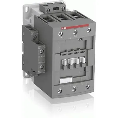
ABB 1SBL391001R8111 is a block contactor designed for reliable switching of 3‑phase power circuits in industrial automation environments. It delivers compact, robust control for motors, conveyors, and pumps while minimizing wiring complexity. Engineers often struggle with coil efficiency, space constraints, and integrating auxiliary feedback in control panels; this device addresses those challenges with a built‑in NO/NC auxiliary contact and a block‑type design that accepts add‑on blocks. The product adheres to IEC/EN 60947‑1 and IEC/EN 60947‑4‑1 and UL/CSA standards, with CE and UKCA declarations, providing regulatory confidence across global projects. By supporting 24 V control, DIN rail mounting, and screw‑terminal wiring, ABB 1SBL391001R8111 offers reliable performance and installation flexibility that reduces commissioning time and total cost of ownership.
Product Information
Extended Description
1SBL391001R8111 ABB: The AFC80-30-11-81 is a 3-pole - 1000 V IEC or 600 V UL contactor with 1 N.O + 1 N.C built-in auxiliary contact and Screw terminals, mainly controlling power circuits up to 125 A (IEC AC-1) or 105 A UL general use. Within the AF platform, AFC contactors offer an optimized operating time for AC controlled applications with electromagnetic coil (control voltage : 24 V AC 50 Hz / 24 V AC 60 Hz). AFC contactors have a block type design and can be easily extended with add-on auxiliary contact blocks and a wide range of additionnal accessories.
Minimum Order Quantity
1 piece
Customs Tariff Number
85364900
Data Sheet, Technical Information
1SBC100219C0201 AFC contactors for AC control applications_Catalog PDF
Instructions and Manuals
Installation instructions AF(C)40(B)...96(B)-30 Contactors, CA4, CAL4, CAT4, CC4, LDC4 Accessories
Instructions and Manuals (Part 2)
Contactors and Overload relays guide
Product Net Width
87 mm
Product Net Depth / Length
119.5 mm
Product Net Height
116 mm
Product Net Weight
1.25 kg
Number of Main Contacts NO
3
Number of Main Contacts NC
0
Number of Auxiliary Contacts NO
1
Number of Auxiliary Contacts NC
1
Number of Poles
3P
Standards
IEC/EN 60947-1, IEC/EN 60947-4-1, UL 60947-4-1, CSA C22.2 No. 60947-4-1, UL 60335-2-40 LZGH2 A2L
Rated Operational Voltage
Main Circuit 1000 V
Conventional Free-air Thermal Current (Ith)
acc. to IEC 60947-4-1, Open Contactors Θ = 40 °C 130 A | acc. to IEC 60947-5-1, Θ = 40 °C 16 A
Rated Operational Current AC-1 (Ie)
(690 V) 40 °C 125 A | (690 V) 60 °C 100 A | (690 V) 70 °C 85 A
Rated Operational Current AC-3 (Ie)
(415 V) 60 °C 80 A | (440 V) 60 °C 80 A | (500 V) 60 °C 65 A | (690 V) 60 °C 49 A | (1000 V) 60 °C 25 A | (380 / 400 V) 60 °C 80 A | (220 / 230 / 240 V) 60 °C 80 A
Rated Operational Current AC-3e (Ie)
(415 V) 60 °C 80 A | (440 V) 60 °C 80 A | (500 V) 60 °C 65 A | (690 V) 60 °C 49 A | (380 / 400 V) 60 °C 80 A | (220 / 230 / 240 V) 60 °C 80 A
Rated Operational Current AC-15 (Ie)
(500 V) NC 2
Rated Operational Current DC-13 (Ie)
(24 V) 6 A / 144 W | (48 V) 2.8 A / 134 W | (72 V) 1 A / 72 W | (110 V) 1.1 A / 121 W | (125 V) 0.55 A / 69 W | (220 V) 0.27 A / 60 W | (250 V) 0.27 A / 68 W | (400 V) 0.15 A / 60 W | (500 V) 0.13 A / 65 W | (600 V) 0.1 A / 60 W
Rated Operational Power AC-3 (Pe)
(415 V) 45 kW | (440 V) 45 kW | (500 V) 45 kW | (690 V) 45 kW | (1000 V) 35 kW | (380 / 400 V) 37 kW | (220 / 230 / 240 V) 22 kW
Rated Operational Power AC-3e (Pe)
(415 V) 45 kW | (440 V) 45 kW | (500 V) 45 kW | (690 V) 45 kW | (380 / 400 V) 37 kW | (220 / 230 / 240 V) 22 kW
Rated Operational Power AC-6b (Pe)
(400 / 415 V) 40 °C, 50 / 60 Hz 48 kvar | (400 / 415 V) 70 °C, 50 / 60 Hz 41 kvar | (400 / 415 V) 55 °C, 50 / 60 Hz 48 kvar | (500 / 550 V), 40 °C, 50 / 60 Hz 60 kvar | (500 / 550 V) 55 °C, 50 / 60 Hz 60 kvar | (500 / 550 V) 70 °C, 50 / 60 Hz 51 kvar | (690 V) 40 °C, 50 / 60 Hz 80 kvar | (690 V) 55 °C, 50 / 60 Hz 80 kvar | (690 V) 70 °C, 50 / 60 Hz 70 kvar
Rated Short-time Withstand Current Low Voltage (Icw)
at 40 °C Ambient Temp, in Free Air, from a Cold State 15 min 140 A | at 40 °C Ambient Temp, in Free Air, from a Cold State 1 min 300 A | at 40 °C Ambient Temp, in Free Air, from a Cold State 1 s 1200 A | at 40 °C Ambient Temp, in Free Air, from a Cold State 30 s 450 A | for 0.1 s 140 A | for 1 s 100 A
Maximum Breaking Capacity
cos phi=0.45 (cos phi=0.35 for Ie > 100 A) at 440 V 1150 A | cos phi=0.45 (cos phi=0.35 for Ie > 100 A) at 690 V 750 A
Rated Insulation Voltage (Ui)
acc. to IEC 60947-4-1 and VDE 0110 (Gr. C) 1000 V | acc. to UL/CSA 600 V
Rated Impulse Withstand Voltage (Uimp)
Auxiliary Circuit 8 kV
Maximum Electrical Switching Frequency
(AC-1) 600 cycles per hour | (AC-15) 1200 cycles per hour | (AC-2 / AC-4) 150 cycles per hour | (AC-3) 1200 cycles per hour | (DC-13) 900 cycles per hour
Maximum Mechanical Switching Frequency
3600 cycles per hour
Rated Control Circuit Voltage (Uc)
50 Hz 24 V | 60 Hz 24 V
Coil Consumption
Average Holding Value 50 / 60 Hz 20 V·A | Average Pull-in Value 50 Hz 236 V·A | Average Pull-in Value 60 Hz 260 V·A
Power Loss
at Rated Operating Conditions AC-1 per Pole 7.6 W | at Rated Operating Conditions AC-3 per Pole 3 W
Operate Time
Between Coil De-energization and NC Contact Closing 7 ... 21 ms | Between Coil De-energization and NO Contact Opening 5 ... 16 ms | Between Coil Energization and NC Contact Opening 3 ... 17 ms | Between Coil Energization and NO Contact Closing 7 ... 22 ms
Mounting on DIN Rail
TH35-15 (35 x 15 mm Mounting Rail) acc. to IEC 60715
Mounting by Screws (not supplied)
2 x M4 or 2 x M6 screws placed diagonally
Connecting Capacity Main Circuit
Flexible with Ferrule 1/2x 6 ... 50 mm² | Flexible with Insulated Ferrule 1/2x 6 ... 50 mm² | Rigid 1x 6 ... 70 mm² | Rigid 2x 6 ... 50 mm² | Rigid 1x 6 ... 70 mm² | Rigid 2x 6 ... 50 mm²
Connecting Capacity Auxiliary Circuit
Flexible with Ferrule 1/2x 0.75 ... 2.5 mm² | Flexible with Insulated Ferrule 1x 0.75 ... 2.5 mm² | Flexible with Insulated Ferrule 2x 0.75 ... 1.5 mm² | Rigid 1/2x 1 ... 2.5 mm²
Connecting Capacity Control Circuit
Flexible with Ferrule 1/2x 0.75 ... 2.5 mm² | Flexible with Insulated Ferrule 1x 0.75 ... 2.5 mm² | Flexible with Insulated Ferrule 2x 0.75 ... 1.5 mm² | Flexible with Insulated Ferrule 1x 0.75 ... 2.5 mm² | Flexible with Insulated Ferrule 2x 0.75 ... 1.5 mm² | Rigid 1/2x 1 ... 2.5 mm²
Wire Stripping Length
Control Circuit 10 mm | Main Circuit 17 mm
Degree of Protection
acc. to IEC 60529, IEC 60947-1, EN 60529 Auxiliary Terminals IP20 | acc. to IEC 60529, IEC 60947-1, EN 60529 Coil Terminals IP20 | acc. to IEC 60529, IEC 60947-1, EN 60529 Main Terminals IP10
Recommended Screw Driver
Main Circuit 4 | Main Circuit Hexagon | Control Circuit 5.5 | Control Circuit Slot
Tightening Torque
Auxiliary Circuit 1.2 N·m | Control Circuit 1.2 N·m | Main Circuit 6 N·m
Terminal Type
Screw Terminals
Product Name
Block Contactor
NEMA Size
3
Continuous Current Rating NEMA
90 A
Horsepower Rating NEMA
(200 V AC) Three Phase 25 Hp | (230 V AC) Three Phase 30 Hp | (460 V AC) Three Phase 50 Hp | (575 V AC) Three Phase 50 Hp
Maximum Operating Voltage UL/CSA
Main Circuit 600 V
General Use Rating UL/CSA
(600 V AC) 105 A
Horsepower Rating UL/CSA
(120 V AC) Single Phase 7-1/2 hp | (200 ... 208 V AC) Three Phase 25 hp | (220 ... 240 V AC) Three Phase 30 hp | (240 V AC) Single Phase 15 hp | (440 ... 480 V AC) Three Phase 60 hp | (550 ... 600 V AC) Three Phase 75 hp
Tightening Torque UL/CSA
Auxiliary Circuit 11 in·lb | Control Circuit 11 in·lb | Main Circuit 53 in·lb
Full Load Amps Motor Use
(120 V AC) Single Phase 80 A | (200 ... 208 V AC) Three Phase 78.2 A | (220 ... 240 V AC) Three Phase 80 A | (240 V AC) Single Phase 68 A | (440 ... 480 V AC) Three Phase 77 A | (550 ... 600 V AC) Three Phase 77 A
Ambient Air Temperature
Close to Contactor without Thermal O/L Relay -40 ... 70 °C | Close to Contactor for Storage -60 ... +80 °C
Climatic Withstand
Category B according to IEC 60947-1 Annex Q
Maximum Operating Altitude Permissible
Without Derating 3000 m
Resistance to Shock acc. to IEC 60068-2-27
Closed, Shock Direction: A 25 g | Closed, Shock Direction: B1 25 g | Closed, Shock Direction: B2 15 g | Closed, Shock Direction: C1 25 g | Closed, Shock Direction: C2 25 g | Open, Shock Direction: B1 5 g
Pollution Degree
3
REACH Declaration
REACH - Letter of Confirmation for block contactors, contactor relays, installation contactors, mini contactors, mini contactor relays, thermal overload relays, electronic overload relays and related accessories
RoHS Information
RoHS II declaration for block contactors, installation contactors, mini contactors, mini contactor relays, thermal overload relays, electronic overload relays and related accessories
RoHS Status
Following EU Directive 2011/65/EU and Amendment 2015/863 July 22, 2019
Toxic Substances Control Act - TSCA
Toxic Substances Control Act (TSCA) declaration for Contactors
WEEE B2C / B2B
Business To Business
WEEE Category
5. Small Equipment (No External Dimension More Than 50 cm)
A2L Certificate – UL
UL-US Certificate of Compliance AFC40 ... AFC96 3-pole contactors - UL 60335-2-40 Household and Similar Electrical Appliances - Safety - Part 2-40: Particular Requirements for Electrical Heat Pumps, Air-Conditioners and Dehumidifiers | UL-CA Certificate of Compliance AFC40 ... AFC96 3-pole contactors - CSA C22.2 No. 60335-2-40 Household and Similar Electrical Appliances - Safety - Part 2-40: Particular Requirements for Electrical Heat Pumps, Air-Conditioners and Dehumidifiers
BV Certificate
BV_2634H36994B1
CB Certificate
CB Certificate AFC80 and AFC96 3-and 4-pole contactors
cULus Certificate
UL-US-L312527-1141-10303102-2
Declaration of Conformity - CE
EU Declaration of Conformity AFC09..(K) ... AFC96 3-pole Contactors
Declaration of Conformity - UKCA
UK Declaration of Conformity AFC09..(K) ... AFC96 3-pole Contactors
DNV Certificate
DNV Certificate AFC09...96 3-pole & AFC09...80 4-pole contactors with screw, push-in terminals
RINA Certificate
Rina Certificate for AFC09...AFC96 3 pole and 4 pole contactors, NFC relays ,screw and spring terminals
UL Certificate
UL-US-2206508-0 | UL-CA-2206439-0
Package Level 1 Units
box 1 piece
Package Level 1 Width
146.5 mm
Package Level 1 Depth / Length
96.5 mm
Package Level 1 Height
146.5 mm
Package Level 1 Gross Weight
1.37 kg
Package Level 1 EAN
3471523019409
Package Level 3 Units
192 piece
Object Classification Code
Q
ETIM 7
EC000066 - Power contactor, AC switching
ETIM 8
EC000066 - Power contactor, AC switching
ETIM 9
EC000066 - Power contactor, AC switching
eClass
V11.0 : 27371003
UNSPSC
39121529
IDEA Granular Category Code (IGCC)
4755 >> Contactors
Feature: Three‑pole block design with a built‑in NO/NC auxiliary contact. Business impact: reduces wiring complexity and enables immediate feedback for interlock and status monitoring. Application: ideal for motor controls, conveyors, and pumps in automation panels. Feature: 24 V AC control coil with defined pull‑in and hold current. Business impact: predictable coil energy consumption lowers heat generation and extends component life. Application: control circuits in machine tools and packaging lines. Feature: Insulation rating up to 1000 V Ui and compliance with IEC/EN 60947‑1, 60947‑4‑1 plus UL/CSA standards. Business impact: simplifies multi‑voltage installations and speeds regulatory approvals. Application: industrial equipment requiring dependable electrical safety and cross‑border certification. Feature: Rated operational currents up to 125 A AC‑1 and 80 A AC‑3, with robust short‑time withstand and high breaking capacity. Business impact: supports demanding motor loads and reduces the number of contactors needed in a line. Application: fans, pumps, and conveyor drives in mid‑ to high‑power automation. Feature: Compact footprint with DIN rail mounting TH35‑15, screw terminals, and precise wiring guidance. Business impact: faster installation, easier maintenance, and reliable torque with 6 N·m main and 1.2 N·m auxiliary. Application: panel builders and OEMs deploying standardized control cabinets. Feature: Add‑on accessory compatibility within the AF platform. Business impact: scalable solutions for expanding control circuits without replacing the base device. Application: retrofit projects and growing automation lines.
Get a Quick Quote for a ABB 1SBL391001R8111
Chat with us on WhatsApp - fast responses guaranteed
Need to speak with someone? We'll call you back within 2 hours during business hours
Interested in ABB 1SBL391001R8111?
Enquire Now
FAQs
Yes. It is designed for DIN Rail TH35‑15 mounting as per IEC 60715, and uses screw terminals for secure main and control wiring, making panel integration straightforward.
AC‑1 rated current is up to 125 A at 690 V and 40 °C (lower at higher temperatures), while AC‑3 ratings include up to 80 A for 415–690 V conditions. These values support typical motor control and capacitor-start loads.
Yes. The AFC contactors use a block design that is easily extended with add‑on auxiliary contact blocks within the AF platform, simplifying feedback wiring and interlocking without replacing the base device.
The coil is 24 V AC (50/60 Hz). Coil power consumption comprises a hold value of about 20 V·A and pull‑in values around 236–260 V·A, with per‑pole power loss of roughly 7.6 W at AC‑1 operation.
It complies with IEC/EN 60947‑1 and 60947‑4‑1, UL 60947‑4‑1, CSA C22.2, and UL/CSA safety standards, with CE and UKCA declarations, reflecting broad regulatory approval for global deployments.