ABB 1SBL391001R8400 Block Contactor - IEC/UL 60947-4-1
Part Number: 1SBL391001R8400
Quick Summary
ABB 1SBL391001R8400 Block Contactor provides reliable AC switching for 3-phase motors. Engineers face voltage sensitivity and coil mismatch that can degrade panel efficiency and cause downtime. Certified to IEC/EN 60947-1 and IEC/EN 60947-4-1 with UL/CSA recognition and CE declarations, it supports global equipment standards. By combining a compact block design with TH35 DIN rail mounting and modular add-ons, it simplifies wiring, reduces panel footprint, and accelerates commissioning while delivering robust performance in automation applications.
Product Information
Extended Description
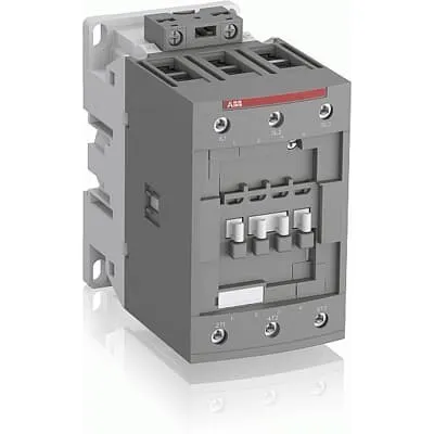
1SBL391001R8400 ABB: The AFC80-30-00-84 is a 3-pole - 1000 V IEC or 600 V UL contactor with Screw terminals, mainly controlling power circuits up to 125 A (IEC AC-1) or 105 A UL general use. Within the AF platform, AFC contactors offer an optimized operating time for AC controlled applications with electromagnetic coil (control voltage : 110 V AC 50 Hz / 110 ... 120 V AC 60 Hz). AFC contactors have a block type design and can be easily extended with add-on auxiliary contact blocks and a wide range of additionnal accessories.
Minimum Order Quantity
1 piece
Customs Tariff Number
85364900
Data Sheet, Technical Information
1SBC100219C0201 AFC contactors for AC control applications_Catalog PDF
Instructions and Manuals
Installation instructions AF(C)40(B)...96(B)-30 Contactors, CA4, CAL4, CAT4, CC4, LDC4 Accessories
Instructions and Manuals (Part 2)
Contactors and Overload relays guide
Product Net Width
70 mm
Product Net Depth / Length
119.5 mm
Product Net Height
116 mm
Product Net Weight
1.21 kg
Number of Main Contacts NO
3
Number of Main Contacts NC
0
Number of Auxiliary Contacts NO
0
Number of Auxiliary Contacts NC
0
Number of Poles
3P
Standards
IEC/EN 60947-1, IEC/EN 60947-4-1, UL 60947-4-1, CSA C22.2 No. 60947-4-1, UL 60335-2-40 LZGH2 A2L
Rated Operational Voltage
Main Circuit 1000 V
Conventional Free-air Thermal Current (Ith)
acc. to IEC 60947-4-1, Open Contactors Θ = 40 °C 130 A
Rated Operational Current AC-1 (Ie)
(690 V) 40 °C 125 A | (690 V) 60 °C 100 A | (690 V) 70 °C 85 A
Rated Operational Current AC-3 (Ie)
(415 V) 60 °C 80 A | (440 V) 60 °C 80 A | (500 V) 60 °C 65 A | (690 V) 60 °C 49 A | (1000 V) 60 °C 25 A | (380 / 400 V) 60 °C 80 A | (220 / 230 / 240 V) 60 °C 80 A
Rated Operational Current AC-3e (Ie)
(415 V) 60 °C 80 A | (440 V) 60 °C 80 A | (500 V) 60 °C 65 A | (690 V) 60 °C 49 A | (380 / 400 V) 60 °C 80 A | (220 / 230 / 240 V) 60 °C 80 A
Rated Operational Power AC-3 (Pe)
(415 V) 45 kW | (440 V) 45 kW | (500 V) 45 kW | (690 V) 45 kW | (1000 V) 35 kW | (380 / 400 V) 37 kW | (220 / 230 / 240 V) 22 kW
Rated Operational Power AC-3e (Pe)
(415 V) 45 kW | (440 V) 45 kW | (500 V) 45 kW | (690 V) 45 kW | (380 / 400 V) 37 kW | (220 / 230 / 240 V) 22 kW
Rated Operational Power AC-6b (Pe)
(400 / 415 V) 40 °C, 50 / 60 Hz 48 kvar | (400 / 415 V) 70 °C, 50 / 60 Hz 41 kvar | (400 / 415 V) 55 °C, 50 / 60 Hz 48 kvar | (500 / 550 V), 40 °C, 50 / 60 Hz 60 kvar | (500 / 550 V) 55 °C, 50 / 60 Hz 60 kvar | (500 / 550 V) 70 °C, 50 / 60 Hz 51 kvar | (690 V) 40 °C, 50 / 60 Hz 80 kvar | (690 V) 55 °C, 50 / 60 Hz 80 kvar | (690 V) 70 °C, 50 / 60 Hz 70 kvar
Rated Short-time Withstand Current Low Voltage (Icw)
at 40 °C Ambient Temp, in Free Air, from a Cold State 15 min 140 A | at 40 °C Ambient Temp, in Free Air, from a Cold State 1 min 300 A | at 40 °C Ambient Temp, in Free Air, from a Cold State 1 s 1200 A | at 40 °C Ambient Temp, in Free Air, from a Cold State 30 s 450 A
Maximum Breaking Capacity
cos phi=0.45 (cos phi=0.35 for Ie > 100 A) at 440 V 1150 A | cos phi=0.45 (cos phi=0.35 for Ie > 100 A) at 690 V 750 A
Rated Insulation Voltage (Ui)
acc. to IEC 60947-4-1 and VDE 0110 (Gr. C) 1000 V | acc. to UL/CSA 600 V
Rated Impulse Withstand Voltage (Uimp)
Auxiliary Circuit 8 kV
Maximum Electrical Switching Frequency
(AC-1) 600 cycles per hour | (AC-2 / AC-4) 150 cycles per hour | (AC-3) 1200 cycles per hour
Maximum Mechanical Switching Frequency
3600 cycles per hour
Rated Control Circuit Voltage (Uc)
50 Hz 110 V | 60 Hz 110 ... 120 V
Coil Consumption
Average Holding Value 50 / 60 Hz 20 V·A | Average Pull-in Value 50 Hz 236 V·A | Average Pull-in Value 60 Hz 260 V·A
Power Loss
at Rated Operating Conditions AC-1 per Pole 7.6 W | at Rated Operating Conditions AC-3 per Pole 3 W
Operate Time
Between Coil De-energization and NC Contact Closing 7 ... 21 ms | Between Coil De-energization and NO Contact Opening 5 ... 16 ms | Between Coil Energization and NC Contact Opening 3 ... 17 ms | Between Coil Energization and NO Contact Closing 7 ... 22 ms
Mounting on DIN Rail
TH35-15 (35 x 15 mm Mounting Rail) acc. to IEC 60715
Mounting by Screws (not supplied)
2 x M4 or 2 x M6 screws placed diagonally
Connecting Capacity Main Circuit
Flexible with Ferrule 1/2x 6 ... 50 mm² | Flexible with Insulated Ferrule 1/2x 6 ... 50 mm² | Rigid 1x 6 ... 70 mm² | Rigid 2x 6 ... 50 mm² | Rigid 1x 6 ... 70 mm² | Rigid 2x 6 ... 50 mm²
Connecting Capacity Control Circuit
Flexible with Ferrule 1/2x 0.75 ... 2.5 mm² | Flexible with Insulated Ferrule 1x 0.75 ... 2.5 mm² | Flexible with Insulated Ferrule 2x 0.75 ... 1.5 mm² | Flexible with Insulated Ferrule 1x 0.75 ... 2.5 mm² | Flexible with Insulated Ferrule 2x 0.75 ... 1.5 mm² | Rigid 1/2x 1 ... 2.5 mm²
Wire Stripping Length
Control Circuit 10 mm | Main Circuit 17 mm
Degree of Protection
acc. to IEC 60529, IEC 60947-1, EN 60529 Auxiliary Terminals IP20 | acc. to IEC 60529, IEC 60947-1, EN 60529 Coil Terminals IP20 | acc. to IEC 60529, IEC 60947-1, EN 60529 Main Terminals IP10
Recommended Screw Driver
Main Circuit 4 | Main Circuit Hexagon | Control Circuit 5.5 | Control Circuit Slot
Tightening Torque
Control Circuit 1.2 N·m | Main Circuit 6 N·m
Terminal Type
Screw Terminals
Product Name
Block Contactor
NEMA Size
3
Continuous Current Rating NEMA
90 A
Horsepower Rating NEMA
(200 V AC) Three Phase 25 Hp | (230 V AC) Three Phase 30 Hp | (460 V AC) Three Phase 50 Hp | (575 V AC) Three Phase 50 Hp
Maximum Operating Voltage UL/CSA
Main Circuit 600 V
General Use Rating UL/CSA
(600 V AC) 105 A
Horsepower Rating UL/CSA
(120 V AC) Single Phase 7-1/2 hp | (200 ... 208 V AC) Three Phase 25 hp | (220 ... 240 V AC) Three Phase 30 hp | (240 V AC) Single Phase 15 hp | (440 ... 480 V AC) Three Phase 60 hp | (550 ... 600 V AC) Three Phase 75 hp
Tightening Torque UL/CSA
Control Circuit 11 in·lb | Main Circuit 53 in·lb
Full Load Amps Motor Use
(120 V AC) Single Phase 80 A | (200 ... 208 V AC) Three Phase 78.2 A | (220 ... 240 V AC) Three Phase 80 A | (240 V AC) Single Phase 68 A | (440 ... 480 V AC) Three Phase 77 A | (550 ... 600 V AC) Three Phase 77 A
Ambient Air Temperature
Close to Contactor without Thermal O/L Relay -40 ... 70 °C | Close to Contactor for Storage -60 ... +80 °C
Climatic Withstand
Category B according to IEC 60947-1 Annex Q
Maximum Operating Altitude Permissible
Without Derating 3000 m
Resistance to Shock acc. to IEC 60068-2-27
Closed, Shock Direction: A 25 g | Closed, Shock Direction: B1 25 g | Closed, Shock Direction: B2 15 g | Closed, Shock Direction: C1 25 g | Closed, Shock Direction: C2 25 g | Open, Shock Direction: B1 5 g
Pollution Degree
3
REACH Declaration
REACH - Letter of Confirmation for block contactors, contactor relays, installation contactors, mini contactors, mini contactor relays, thermal overload relays, electronic overload relays and related accessories
RoHS Information
RoHS II declaration for block contactors, installation contactors, mini contactors, mini contactor relays, thermal overload relays, electronic overload relays and related accessories
RoHS Status
Following EU Directive 2011/65/EU and Amendment 2015/863 July 22, 2019
Toxic Substances Control Act - TSCA
Toxic Substances Control Act (TSCA) declaration for Contactors
WEEE B2C / B2B
Business To Business
WEEE Category
5. Small Equipment (No External Dimension More Than 50 cm)
A2L Certificate – UL
UL-US Certificate of Compliance AFC40 ... AFC96 3-pole contactors - UL 60335-2-40 Household and Similar Electrical Appliances - Safety - Part 2-40: Particular Requirements for Electrical Heat Pumps, Air-Conditioners and Dehumidifiers | UL-CA Certificate of Compliance AFC40 ... AFC96 3-pole contactors - CSA C22.2 No. 60335-2-40 Household and Similar Electrical Appliances - Safety - Part 2-40: Particular Requirements for Electrical Heat Pumps, Air-Conditioners and Dehumidifiers
BV Certificate
BV_2634H36994B1
CB Certificate
CB Certificate AFC80 and AFC96 3-and 4-pole contactors
cULus Certificate
UL-US-L312527-1141-10303102-2
Declaration of Conformity - CE
EU Declaration of Conformity AFC09..(K) ... AFC96 3-pole Contactors
Declaration of Conformity - UKCA
UK Declaration of Conformity AFC09..(K) ... AFC96 3-pole Contactors
DNV Certificate
DNV Certificate AFC09...96 3-pole & AFC09...80 4-pole contactors with screw, push-in terminals
RINA Certificate
Rina Certificate for AFC09...AFC96 3 pole and 4 pole contactors, NFC relays ,screw and spring terminals
UL Certificate
UL-US-2206508-0 | UL-CA-2206439-0
Package Level 1 Units
box 1 piece
Package Level 1 Width
146.5 mm
Package Level 1 Depth / Length
96.5 mm
Package Level 1 Height
146.5 mm
Package Level 1 Gross Weight
1.33 kg
Package Level 1 EAN
3471523019362
Package Level 3 Units
192 piece
Object Classification Code
Q
ETIM 7
EC000066 - Power contactor, AC switching
ETIM 8
EC000066 - Power contactor, AC switching
ETIM 9
EC000066 - Power contactor, AC switching
eClass
V11.0 : 27371003
UNSPSC
39121529
IDEA Granular Category Code (IGCC)
4755 >> Contactors
Coil voltage compatibility ensures consistent control across 50 Hz and 60 Hz networks, reducing coil overheating and improving reliability in mixed-voltage installations. This translates to lower maintenance and fewer unscheduled outages in HVAC, conveyor, and pump control panels. The 3-pole single-block design supports AC-1 and AC-3 operating modes up to 125 A, enabling efficient motor start/stop sequences in demanding industrial environments. AIEC insulation rating of 1000 V and a maximum switching capacity of 1150 A cos(phi 0.45) at 440 V ensures safe panel design and long life under peak loads. The DIN-rail mounting (TH35-15) and screw-terminal connections provide fast installation and secure wiring ready for field servicing. Availability of add-on auxiliary contact blocks and accessories simplifies expansion without rework, improving time-to-production. Compatibility with wide wire ranges (main circuit up to 70 mm², control circuit 0.75–2.5 mm²) supports diverse panel layouts and retrofit projects. The product’s compact footprint (70 mm width, 119.5 mm depth) aids enclosure design while preserving headroom for thermal management. Robust IP20 coil/aux terminals and IP10 main terminals offer reliable operation in standard industrial environments. Industry-specific design considerations, such as ETIM and UNSPSC classification, streamline parts sourcing and procurement across global facilities.
Get a Quick Quote for a ABB 1SBL391001R8400
Chat with us on WhatsApp - fast responses guaranteed
Need to speak with someone? We'll call you back within 2 hours during business hours
Interested in ABB 1SBL391001R8400?
Enquire Now
FAQs
To install on a DIN rail, align the TH35-15 mounting profile with the panel rail and snap the unit into place. For secure mounting, you may use two screws if preferred. Wire the main circuit with flexible or rigid conductors up to 70 mm² and the control circuit with 0.75–2.5 mm². Ensure coil terminals are protected and verify IP ratings during commissioning.
The contactor supports AC-1 up to 125 A at 690 V (60 °C) with a 1000 V insulation voltage. For AC-3/AC-3e, ratings are 80 A across various voltages (415–690 V depending on temperature), with rated main contacts of 3 NO and 0 NC. These figures enable reliable motor starting and switching under typical industrial loads.
Yes. The coil is designed for 110 V AC at 50 Hz or 110–120 V AC at 60 Hz, with measured coil consumption values (holding 20 V·A; pull-in 236–260 V·A depending on frequency). This compatibility supports standard PLC and relay control schemes, reducing the need for adapters or transformers in control cabinets.
The device complies with IEC/EN 60947-1 and 60947-4-1, and carries UL/CSA listings, CE declarations, and relevant safety certificates (UL/CA, CB, DNV, RINA where referenced). It also aligns with RoHS and REACH requirements, supporting safe integration into global machinery and ensuring regulatory compliance for industrial equipment.
Main circuit terminals accept 1/2x 6–50 mm² flexible with ferrule, rigid 1x 6–70 mm², and control circuit accepts 0.75–2.5 mm² sizes. Wire stripping is 17 mm for main, 10 mm for control. Use 2 x M4 or 2 x M6 screws for mounting and ensure IP ratings are maintained. This setup minimizes loose connections and improves vibration resistance in harsh environments.