ABB 1SBL391201R3400 Block Contactor - IEC/EN 60947-4-1, UL 60947-4-1
Part Number: 1SBL391201R3400
Quick Summary
ABB 1SBL391201R3400 block contactor is designed to reliably switch power circuits in industrial automation, motor control, and packaging lines. Engineers often face coil voltage compatibility and space constraints in panel cabinets; this device addresses those pain points with versatile coil options and a compact footprint. It complies with IEC/EN 60947-4-1 and UL 60947-4-1 alongside CE/UKCA declarations, providing safety and regulatory assurance. The combination of robust electrical ratings and easy installation delivers real business value by reducing panel size, installation time, and lifecycle risk while supporting AC-1 and AC-3 control duties in harsh environments.
Product Information
Extended Description
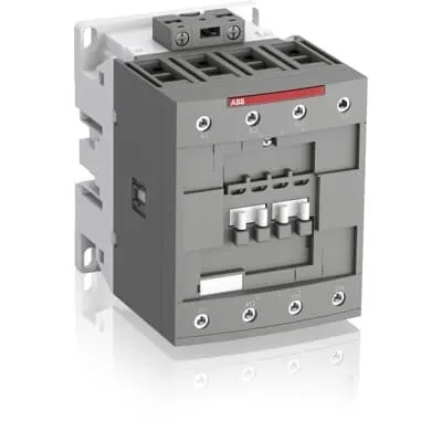
1SBL391201R3400 ABB: The AFC80-40-00-34 is a 4-pole (4 N.O) - 1000 V IEC or 600 V UL contactor with Screw terminals, mainly controlling power circuits up to 125 A (IEC AC-1) or 105 A UL general use. Within the AF platform, AFC contactors offer an optimized operating time for AC controlled applications with electromagnetic coil (control voltage : 175 V AC 50 Hz / 208 V AC 60 Hz). AFC contactors have a block type design and can be easily extended with add-on auxiliary contact blocks and a wide range of additionnal accessories.
Minimum Order Quantity
1 piece
Customs Tariff Number
85364900
Data Sheet, Technical Information
1SBC100219C0201 AFC contactors for AC control applications_Catalog PDF
Instructions and Manuals
Installation instructions AF(C)40(B)...80(B)-40/22 Contactors, CA4, CAL4, CAT4, CC4, LDC4 Accessories
Instructions and Manuals (Part 2)
Contactors and Overload relays guide
Product Net Width
90 mm
Product Net Depth / Length
119.5 mm
Product Net Height
116 mm
Product Net Weight
1.45 kg
Number of Main Contacts NO
4
Number of Main Contacts NC
0
Number of Auxiliary Contacts NO
0
Number of Auxiliary Contacts NC
0
Number of Poles
4P
Standards
IEC/EN 60947-1, IEC/EN 60947-4-1, UL 60947-1, UL 60947-4-1, CSA C22.2 No. 60947-1, CSA C22.2 No. 60947-4-1
Rated Operational Voltage
Main Circuit 1000 V
Rated Frequency (f)
Auxiliary Circuit 50 / 60 Hz | Main Circuit 50 / 60 Hz
Conventional Free-air Thermal Current (Ith)
acc. to IEC 60947-4-1, Open Contactors Θ = 40 °C 125 A
Rated Operational Current AC-1 (Ie)
(690 V) 40 °C 125 A | (690 V) 60 °C 105 A | (690 V) 70 °C 90 A
Rated Operational Current AC-3 (Ie)
(415 V) 60 °C 80 A | (440 V) 60 °C 80 A | (500 V) 60 °C 65 A | (690 V) 60 °C 49 A | (1000 V) 60 °C 25 A | (380 / 400 V) 60 °C 80 A | (220 / 230 / 240 V) 60 °C 80 A
Rated Operational Power AC-3 (Pe)
(415 V) 45 kW | (440 V) 45 kW | (500 V) 45 kW | (690 V) 45 kW | (380 / 400 V) 37 kW | (220 / 230 / 240 V) 22 kW
Rated Short-time Withstand Current Low Voltage (Icw)
at 40 °C Ambient Temp, in Free Air, from a Cold State 15 min 140 A | at 40 °C Ambient Temp, in Free Air, from a Cold State 1 min 300 A | at 40 °C Ambient Temp, in Free Air, from a Cold State 1 s 1200 A | at 40 °C Ambient Temp, in Free Air, from a Cold State 30 s 450 A
Maximum Breaking Capacity
cos phi=0.45 (cos phi=0.35 for Ie > 100 A) at 440 V 1150 A | cos phi=0.45 (cos phi=0.35 for Ie > 100 A) at 690 V 750 A
Rated Insulation Voltage (Ui)
acc. to IEC 60947-4-1 and VDE 0110 (Gr. C) 1000 V | acc. to UL/CSA 600 V
Rated Impulse Withstand Voltage (Uimp)
Auxiliary Circuit 8 kV
Maximum Electrical Switching Frequency
(AC-1) 600 cycles per hour
Maximum Mechanical Switching Frequency
3600 cycles per hour
Rated Control Circuit Voltage (Uc)
50 Hz 175 V | 60 Hz 208 V
Coil Consumption
Average Holding Value 50 / 60 Hz 20 V·A | Average Pull-in Value 50 Hz 236 V·A | Average Pull-in Value 60 Hz 260 V·A
Power Loss
at Rated Operating Conditions AC-1 per Pole 8 W | at Rated Operating Conditions AC-3 per Pole 3.2 W
Operate Time
Between Coil De-energization and NC Contact Closing 10 ... 19 ms | Between Coil De-energization and NO Contact Opening 5 ... 16 ms | Between Coil Energization and NC Contact Opening 6 ... 15 ms | Between Coil Energization and NO Contact Closing 7 ... 22 ms
Mounting on DIN Rail
TH35-15 (35 x 15 mm Mounting Rail) acc. to IEC 60715 | TH35-7.5 (35 x 7.5 mm Mounting Rail) acc. to IEC 60715
Mounting by Screws (not supplied)
2 x M4 or 2 x M6 screws placed diagonally
Connecting Capacity Main Circuit
Flexible with Ferrule 1/2x 6 ... 50 mm² | Flexible with Insulated Ferrule 1/2x 6 ... 50 mm² | Rigid 1x 6 ... 70 mm² | Rigid 2x 6 ... 50 mm²
Connecting Capacity Control Circuit
Flexible with Ferrule 1/2x 0.75 ... 2.5 mm² | Flexible with Insulated Ferrule 1x 0.75 ... 2.5 mm² | Flexible with Insulated Ferrule 2x 0.75 ... 1.5 mm² | Rigid 1/2x 1 ... 2.5 mm²
Wire Stripping Length
Control Circuit 10 mm | Main Circuit 17 mm
Degree of Protection
acc. to IEC 60529, IEC 60947-1, EN 60529 Auxiliary Terminals IP20 | acc. to IEC 60529, IEC 60947-1, EN 60529 Coil Terminals IP20 | acc. to IEC 60529, IEC 60947-1, EN 60529 Main Terminals IP10
Recommended Screw Driver
Main Circuit 4 | Main Circuit Hexagon | Control Circuit 5.5 | Control Circuit Slot
Tightening Torque
Control Circuit 1.2 N·m | Main Circuit 6 N·m
Terminal Type
Screw Terminals
Product Name
Block Contactor
Maximum Operating Voltage UL/CSA
Main Circuit 600 V
General Use Rating UL/CSA
(600 V AC) 105 A
Tightening Torque UL/CSA
Control Circuit 11 in·lb | Main Circuit 53 in·lb
Ambient Air Temperature
Close to Contactor for Storage -60 ... +80 °C | Near Contactor for Operation in Free Air -40 ... 70 °C | Near Contactor for Operation in Free Air (0.85 ... 1.1 Uc) -40 ... +60 °C | Near Contactor for Operation in Free Air (Uc) -40 ... 70 °C
Climatic Withstand
Category B according to IEC 60947-1 Annex Q
Maximum Operating Altitude Permissible
Without Derating 3000 m
Pollution Degree
3
REACH Declaration
REACH - Letter of Confirmation for block contactors, contactor relays, installation contactors, mini contactors, mini contactor relays, thermal overload relays, electronic overload relays and related accessories
RoHS Information
RoHS II declaration for block contactors, installation contactors, mini contactors, mini contactor relays, thermal overload relays, electronic overload relays and related accessories
RoHS Status
Following EU Directive 2011/65/EU and Amendment 2015/863 July 22, 2019
Toxic Substances Control Act - TSCA
Toxic Substances Control Act (TSCA) declaration for Contactors
WEEE B2C / B2B
Business To Business
WEEE Category
5. Small Equipment (No External Dimension More Than 50 cm)
BV Certificate
BV_2634H36994B1
CB Certificate
CB Certificate AFC80 and AFC96 3-and 4-pole contactors
Declaration of Conformity - CE
EU Declaration of Conformity AFC09 ... AFC80 4-pole Contactors
Declaration of Conformity - UKCA
UK Declaration of Conformity AFC09 ... AFC80 4-pole Contactors
DNV Certificate
DNV Certificate AFC09...96 3-pole & AFC09...80 4-pole contactors with screw, push-in terminals
RINA Certificate
Rina Certificate for AFC09...AFC96 3 pole and 4 pole contactors, NFC relays ,screw and spring terminals
UL Certificate
UL-US Certificate of Compliance AFC40 ... AFC80 4-pole contactors | UL-CA Certificate of Compliance AFC40 ... AFC80 4-pole contactors
Package Level 1 Units
box 1 piece
Package Level 1 Width
146.5 mm
Package Level 1 Depth / Length
97.5 mm
Package Level 1 Height
146.5 mm
Package Level 1 Gross Weight
1.77 kg
Package Level 1 EAN
3471523024588
Object Classification Code
Q
ETIM 7
EC000066 - Power contactor, AC switching
ETIM 8
EC000066 - Power contactor, AC switching
ETIM 9
EC000066 - Power contactor, AC switching
eClass
V11.0 : 27371003
UNSPSC
39121529
IDEA Granular Category Code (IGCC)
4755 >> Contactors
Feature: Four-pole, four NO main contacts with 1000 V insulation. Business Impact: Enables handling higher power loads with a compact footprint, reducing panel depth and wiring complexity in control cabinets. Application: Ideal for motor control and conveyor drives where space is at a premium. Feature: Coil voltage options of 175 V AC (50 Hz) and 208 V AC (60 Hz). Business Impact: Simplifies integration with common control systems and reduces inventory by supporting multiple control voltages. Application: Tight control panels requiring versatile control voltage compatibility. Feature: Screw terminals for main and control circuits. Business Impact: Provides secure, vibration-resistant connections with straightforward field wiring, lowering maintenance needs. Application: Heavy-duty installations in manufacturing lines. Feature: DIN rail mounting TH35-15 or TH35-7.5 plus screw mounting capability. Business Impact: Accelerates installation and simplifies retrofits in existing panels, saving commissioning time. Application: OEM panel builds and upgrade projects. Feature: High current capability with IEC/UL ratings and defined ITE/Ie values. Business Impact: Ensures reliable operation under IEC AC-1 up to 125 A and AC-3 up to 80 A at various voltages, improving system availability. Application: Pumping stations, presses, and material handling systems. Feature: Low coil power loss and fast operate times. Business Impact: Reduces energy usage and improves system response, contributing to overall efficiency. Application: High-frequency switching scenarios in automation loops. Feature: Robust environmental and safety certifications. Business Impact: Facilitates compliance across regional markets, reducing time-to-market. Application: Global deployments with CE/UKCA, UL, CSA, and more. The combination of compatibility, installations advantages, and documented performance supports predictable maintenance planning and total cost of ownership reductions across manufacturing facilities.
Get a Quick Quote for a ABB 1SBL391201R3400
Chat with us on WhatsApp - fast responses guaranteed
Need to speak with someone? We'll call you back within 2 hours during business hours
Interested in ABB 1SBL391201R3400?
Enquire Now
FAQs
This contactor is designed for TH35-15 or TH35-7.5 DIN rail mounting. Attach using the compatible rail clip, then secure with 2 x M4 or 2 x M6 screws diagonally if mounting outside the rail. Connect main circuit wires to the 1/2 x 6 … 50 mm² terminals and control circuit wires to 0.75 … 2.5 mm² terminals. Torque main: 6 N·m; control: 1.2 N·m.
For AC-1, Ie is 125 A at 40 °C, 105 A at 60 °C, and 90 A at 70 °C for 690 V systems. For AC-3, Ie ranges from 80 A at 415–440 V to 25 A at 1000 V, with corresponding Pe values up to 45 kW in the 380–690 V range and 22 kW at 220–240 V. These ratings guide motor and load sizing.
Yes. It is rated for main circuit insulation up to 1000 V and supports up to 125 A for AC-1 duty at 690 V and up to 80 A for AC-3 at higher voltages. Its compact form factor and screw-terminal connections streamline installation in 1000 V panels while maintaining regulatory compliance.
The device carries IEC/EN 60947-1 and 60947-4-1 standards, UL 60947-1 and 60947-4-1, CSA equivalents, and CE/UKCA declarations. It also lists BV, CB, DNV, and RINA certifications, expanding global acceptance. This broad certification set supports safe operation, cross-border sales, and regulatory alignment in diverse markets.
Expect 8 W per pole in rated operating conditions for power loss, with operate times between 5 and 22 ms depending on coil energization. The unit supports up to 600 switching cycles per hour (AC-1) and 3600 mechanical cycles per hour, so plan maintenance around wear on main contacts and verify torque on terminations during routine checks.