ABB 1SBL391501R8500 Block Contactor - 1000V IEC/UL
Part Number: 1SBL391501R8500
Quick Summary
ABB 1SBL391501R8500 Block Contactor is a high‑reliability four‑pole power switch designed for industrial automation and motor control. It enables robust AC switching in machines, conveyors, pumps, and drives with a compact footprint. Users often struggle with inconsistent coil response, limited mounting options, and insufficient insulation ratings when integrating contactors into control panels. This model delivers on both reliability and versatility by meeting key standards and offering a clear path to scalable control architectures. With IEC/EN 60947‑4‑1 and UL 60947‑4‑1 compliance, CE declarations, and broad compatibility, it supports efficient maintenance, safer operations, and faster project timelines while reducing total cost of ownership.
Product Information
Extended Description
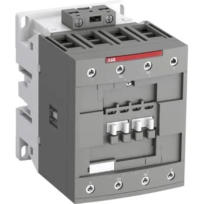
1SBL391501R8500 ABB: The AFC80-22-00-85 is a 4-pole (2 N.O + 2 N.C) - 1000 V IEC or 600 V UL contactor with Screw terminals, mainly controlling power circuits up to 125 A (IEC AC-1) or 105 A UL general use. Within the AF platform, AFC contactors offer an optimized operating time for AC controlled applications with electromagnetic coil (control voltage : 380 ... 400 V AC 50 Hz / 400 ... 415 V AC 60 Hz). AFC contactors have a block type design and can be easily extended with add-on auxiliary contact blocks and a wide range of additionnal accessories.
Minimum Order Quantity
1 piece
Customs Tariff Number
85364900
Data Sheet, Technical Information
1SBC100219C0201 AFC contactors for AC control applications_Catalog PDF
Instructions and Manuals
Installation instructions AF(C)40(B)...80(B)-40/22 Contactors, CA4, CAL4, CAT4, CC4, LDC4 Accessories
Instructions and Manuals (Part 2)
Contactors and Overload relays guide
Product Net Width
90 mm
Product Net Depth / Length
119.5 mm
Product Net Height
116 mm
Product Net Weight
1.45 kg
Number of Main Contacts NO
2
Number of Main Contacts NC
2
Number of Auxiliary Contacts NO
0
Number of Auxiliary Contacts NC
0
Number of Poles
4P
Standards
IEC/EN 60947-1, IEC/EN 60947-4-1, UL 60947-1, UL 60947-4-1, CSA C22.2 No. 60947-1, CSA C22.2 No. 60947-4-1
Rated Operational Voltage
Main Circuit 1000 V
Conventional Free-air Thermal Current (Ith)
acc. to IEC 60947-4-1, Open Contactors Θ = 40 °C 125 A
Rated Operational Current AC-1 (Ie)
(690 V) 40 °C 125 A | (690 V) 60 °C 105 A | (690 V) 70 °C 90 A
Rated Operational Current AC-3 (Ie)
(415 V) 60 °C 80 A | (440 V) 60 °C 80 A | (500 V) 60 °C 65 A | (690 V) 60 °C 49 A | (1000 V) 60 °C 25 A | (380 / 400 V) 60 °C 80 A | (220 / 230 / 240 V) 60 °C 80 A
Rated Operational Power AC-3 (Pe)
(415 V) 45 kW | (440 V) 45 kW | (500 V) 45 kW | (690 V) 45 kW | (1000 V) 35 kW | (380 / 400 V) 37 kW | (220 / 230 / 240 V) 22 kW
Rated Short-time Withstand Current Low Voltage (Icw)
at 40 °C Ambient Temp, in Free Air, from a Cold State 15 min 140 A | at 40 °C Ambient Temp, in Free Air, from a Cold State 1 min 300 A | at 40 °C Ambient Temp, in Free Air, from a Cold State 1 s 1200 A | at 40 °C Ambient Temp, in Free Air, from a Cold State 30 s 450 A
Maximum Breaking Capacity
cos phi=0.45 (cos phi=0.35 for Ie > 100 A) at 440 V 1150 A | cos phi=0.45 (cos phi=0.35 for Ie > 100 A) at 690 V 750 A
Rated Insulation Voltage (Ui)
acc. to IEC 60947-4-1 and VDE 0110 (Gr. C) 1000 V | acc. to UL/CSA 600 V
Rated Impulse Withstand Voltage (Uimp)
Auxiliary Circuit 8 kV
Maximum Electrical Switching Frequency
(AC-1) 600 cycles per hour | (AC-2 / AC-4) 0 cycles per hour
Maximum Mechanical Switching Frequency
3600 cycles per hour
Rated Control Circuit Voltage (Uc)
50 Hz 380 ... 400 V | 60 Hz 400 ... 415 V
Coil Consumption
Average Holding Value 50 / 60 Hz 20 V·A | Average Pull-in Value 50 Hz 236 V·A | Average Pull-in Value 60 Hz 260 V·A
Power Loss
at Rated Operating Conditions AC-1 per Pole 8 W | at Rated Operating Conditions AC-3 per Pole 3.2 W
Operate Time
Between Coil De-energization and NC Contact Closing 10 ... 19 ms | Between Coil De-energization and NO Contact Opening 5 ... 16 ms | Between Coil Energization and NC Contact Opening 6 ... 15 ms | Between Coil Energization and NO Contact Closing 7 ... 22 ms
Mounting on DIN Rail
TH35-15 (35 x 15 mm Mounting Rail) acc. to IEC 60715
Mounting by Screws (not supplied)
2 x M4 or 2 x M6 screws placed diagonally
Connecting Capacity Main Circuit
Flexible with Ferrule 1/2x 6 ... 50 mm² | Flexible with Insulated Ferrule 1/2x 6 ... 50 mm² | Rigid 1x 6 ... 70 mm² | Rigid 2x 6 ... 50 mm² | Rigid 1x 6 ... 70 mm² | Rigid 2x 6 ... 50 mm²
Connecting Capacity Control Circuit
Flexible with Ferrule 1/2x 0.75 ... 2.5 mm² | Flexible with Insulated Ferrule 1x 0.75 ... 2.5 mm² | Flexible with Insulated Ferrule 2x 0.75 ... 1.5 mm² | Rigid 1/2x 1 ... 2.5 mm²
Wire Stripping Length
Control Circuit 10 mm | Main Circuit 17 mm
Degree of Protection
acc. to IEC 60529, IEC 60947-1, EN 60529 Auxiliary Terminals IP20 | acc. to IEC 60529, IEC 60947-1, EN 60529 Coil Terminals IP20 | acc. to IEC 60529, IEC 60947-1, EN 60529 Main Terminals IP10
Recommended Screw Driver
Main Circuit 4 | Main Circuit Hexagon | Control Circuit 5.5 | Control Circuit Slot
Tightening Torque
Control Circuit 1.2 N·m | Main Circuit 6 N·m
Terminal Type
Screw Terminals
Product Name
Block Contactor
Maximum Operating Voltage UL/CSA
Main Circuit 600 V
General Use Rating UL/CSA
(600 V AC) 105 A
Tightening Torque UL/CSA
Control Circuit 11 in·lb | Main Circuit 53 in·lb
Full Load Amps Motor Use
(120 V AC) Single Phase 7-1/2 A | (200 ... 208 V AC) Three Phase 25 A | (220 ... 240 V AC) Three Phase 30 A | (240 V AC) Single Phase 15 A | (440 ... 480 V AC) Three Phase 60 A | (550 ... 600 V AC) Three Phase 75 A
Ambient Air Temperature
Close to Contactor without Thermal O/L Relay -40 ... 70 °C | Close to Contactor for Storage -60 ... +80 °C | Near Contactor for Operation in Free Air -40 ... 70 °C
Climatic Withstand
Category B according to IEC 60947-1 Annex Q
Maximum Operating Altitude Permissible
Without Derating 3000 m
Pollution Degree
3
REACH Declaration
REACH - Letter of Confirmation for block contactors, contactor relays, installation contactors, mini contactors, mini contactor relays, thermal overload relays, electronic overload relays and related accessories
RoHS Information
RoHS II declaration for block contactors, installation contactors, mini contactors, mini contactor relays, thermal overload relays, electronic overload relays and related accessories
RoHS Status
Following EU Directive 2011/65/EU and Amendment 2015/863 July 22, 2019
Toxic Substances Control Act - TSCA
Toxic Substances Control Act (TSCA) declaration for Contactors
WEEE B2C / B2B
Business To Business
WEEE Category
5. Small Equipment (No External Dimension More Than 50 cm)
BV Certificate
BV_2634H36994B1
CB Certificate
CB Certificate AFC80 and AFC96 3-and 4-pole contactors
Declaration of Conformity - CE
EU Declaration of Conformity AFC09 ... AFC80 4-pole Contactors
Declaration of Conformity - UKCA
UK Declaration of Conformity AFC09 ... AFC80 4-pole Contactors
DNV Certificate
DNV Certificate AFC09...96 3-pole & AFC09...80 4-pole contactors with screw, push-in terminals
RINA Certificate
Rina Certificate for AFC09...AFC96 3 pole and 4 pole contactors, NFC relays ,screw and spring terminals
UL Certificate
UL-US Certificate of Compliance AFC40 ... AFC80 4-pole contactors | UL-CA Certificate of Compliance AFC40 ... AFC80 4-pole contactors
Package Level 1 Units
box 1 piece
Package Level 1 Width
146.5 mm
Package Level 1 Depth / Length
97.5 mm
Package Level 1 Height
146.5 mm
Package Level 1 Gross Weight
1.77 kg
Package Level 1 EAN
3471523019485
Package Level 3 Units
192 piece
Object Classification Code
Q
ETIM 7
EC000066 - Power contactor, AC switching
ETIM 8
EC000066 - Power contactor, AC switching
ETIM 9
EC000066 - Power contactor, AC switching
eClass
V11.0 : 27371003
UNSPSC
39121529
IDEA Granular Category Code (IGCC)
4755 >> Contactors
Feature → Business Impact → Application. The 4P block design with 2 normally open and 2 normally closed main contacts provides balanced switching for demanding loads, enabling controlled startup sequences and smoother motor protection in high‑demand line applications. This configuration, combined with a 1000 V rated insulation voltage, improves safety margins and reduces the number of components required in complex control schemes, delivering measurable reductions in wiring complexity and fault potential in rolling stock, packaging lines, and material handling systems. The coil accepts 380–400 V AC at 50 Hz or 400–415 V AC at 60 Hz, ensuring compatibility with common European and North American drive voltages, which simplifies procurement and reduces installation risk in mixed‑voltage environments. DIN rail mounting (TH35‑15) and panel mounting flexibility (screw terminals) support rapid panel integration and serviceability, minimizing downtime during maintenance or expansions. Compliance with IEC/EN 60947‑1, IEC/EN 60947‑4‑1, UL/CSA standards, and CE declarations provides a clear path to regulatory acceptance, boosting supplier confidence and audit readiness. The device’s compact weight (about 1.45 kg) and robust construction support enclosure space optimization while maintaining thermal and electrical performance under duty conditions. Availability of add‑on auxiliary contact blocks and accessories enables scalable control architectures without replacing existing hardware, helping projects grow with demand while preserving existing investments.
Get a Quick Quote for a ABB 1SBL391501R8500
Chat with us on WhatsApp - fast responses guaranteed
Need to speak with someone? We'll call you back within 2 hours during business hours
Interested in ABB 1SBL391501R8500?
Enquire Now
FAQs
Mounting is designed for TH35-15 DIN rails, with additional recommendations for screw mounting using 2× M4 or 2× M6 screws placed diagonally if rail mounting is not feasible. The unit ships with screw terminals for secure, vibration‑resistant connections and supports quick panel integration. Ensure adequate clearance for heat dissipation and verify coil voltage matches the control circuit (380–400 V or 400–415 V depending on your mains frequency). This approach minimizes downtime during maintenance and provides straightforward expansion with add‑on auxiliary contact blocks.
For AC-1 operation at 690 V and 40 °C, the device handles up to 125 A, with 105 A at 690 V and 60 °C, and 90 A at 70 °C. For AC-3 at various voltages, it supports up to 80 A at 60 °C (415–690 V) and scales to 65 A at higher voltages (500–690 V). This makes the contactor suitable for motor starting and other motor control tasks where reduced torque surges are essential, while delivering reliable switching performance in demanding control circuits.
Yes. The product adheres to IEC/EN 60947‑1 and IEC/EN 60947‑4‑1 standards and additionally supports UL 60947‑1 and UL 60947‑4‑1, CSA equivalents, plus CE declarations. This combination covers many global regulatory requirements, simplifying cross‑border procurement and ensuring the device can be incorporated into regulated industrial environments with reduced certification effort and audit risk.
The AFC platform design enables easy extension with add‑on auxiliary contact blocks and a wide range of accessories, allowing control circuits to be expanded without replacing the main device. Compatible options include auxiliary contacts for signaling and protection relays, along with mounting hardware and terminal adapters. This supports scalable control architectures, enhanced diagnostics, and easier integration into automated lines and machines.
Maintenance benefits derive from its screw terminals and robust 4P construction, which offer reliable long‑term operation with minimal loose connections. The coil consumption figures (holding and pull‑in for 50/60 Hz) support predictable energy draw, contributing to lower running costs. Its rated power loss and mechanical/ electrical switching frequencies provide a clear basis for life expectancy estimates, enabling proactive maintenance planning and reduced unexpected downtime in critical production lines.