ABB AF80-30-22-11 Block Contactor - IEC/UL Certifications
Part Number: 1SBL397001R1122
Quick Summary
Block Contactor ABB AF80-30-22-11 enables reliable motor control in automation and packaging lines. The wide control voltage range (24–60 V AC/50/60 Hz and 20–60 V DC) reduces panel energy consumption and minimizes nuisance tripping during voltage fluctuations. Built-in surge protection and a compact block design simplify wiring and panel layout, while AF technology supports easy expansion with add-on auxiliary contact blocks. With three main NO contacts and two NO/ two NC auxiliary contacts, it handles complex control circuits in tight spaces. Certified to IEC/EN 60947-1, IEC/EN 60947-4-1, and UL 60335-2-40, it meets global safety standards. This combination delivers reliable performance, improved uptime, and cost-effective maintenance for industrial applications.
Product Information
Extended Description
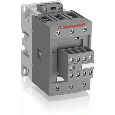
1SBL397001R1122 ABB: The AF80-30-22-11 is a 3 pole - 1000 V IEC or 600 UL contactor with pre-mounted auxiliary contacts and screw terminals, controlling motors up to 37 kW / 400 V AC (AC-3) or 60 hp / 480 V UL and switching power circuits up to 125 A (AC-1) or 105 A UL general use. Thanks to the AF technology, the contactor has a wide control voltage range (24-60 V 50/60 Hz and 20-60 V DC), managing large control voltage variations, reducing panel energy consumptions and ensuring distinct operations in unstable networks. Furthermore, surge protection is built-in, offering a compact solution. AF contactors have a block type design, can be easily extended with add-on auxiliary contact blocks and an additional wide range of accessories.
Minimum Order Quantity
1 piece
Customs Tariff Number
85364900
Data Sheet, Technical Information
1SBC100214C0202 - Main catalog Motor protection and control Manual motor starters, contactors and overload relays (PDF) - Edition 2024
Instructions and Manuals
Installation instructions AF(C)40(B)...96(B)-30 Contactors, CA4, CAL4, CAT4, CC4, LDC4 Accessories
Instructions and Manuals (Part 2)
Contactors and Overload relays guide
CAD Dimensional Drawing
Information - 2D and 3D files for CAD systems
Product Net Width
70 mm
Product Net Depth / Length
149 mm
Product Net Height
125.5 mm
Product Net Weight
1.27 kg
Number of Main Contacts NO
3
Number of Main Contacts NC
0
Number of Auxiliary Contacts NO
2
Number of Auxiliary Contacts NC
2
Number of Poles
3P
Standards
IEC/EN 60947-1, IEC/EN 60947-4-1, UL 60335-2-40 LZGH2 A2L, UL 60947-1, UL 60947-4-1, CSA C22.2 No. 60335-2-40 LZGH2 A2L, CSA C22.2 No. 60947-1:22, CSA C22.2 No. 60947-4-1:22
Rated Operational Voltage
Auxiliary Circuit 690 V | Main Circuit 1000 V
Rated Frequency (f)
Auxiliary Circuit 50 / 60 Hz | Control Circuit 50 / 60 Hz | Main Circuit 50 / 60 Hz
Conventional Free-air Thermal Current (Ith)
acc. to IEC 60947-4-1, Open Contactors Θ = 40 °C 130 A | acc. to IEC 60947-5-1, Θ = 40 °C 16 A
Rated Operational Current AC-1 (Ie)
(690 V) 40 °C 125 A | (690 V) 60 °C 100 A | (690 V) 70 °C 85 A
Rated Operational Current AC-3 (Ie)
(415 V) 60 °C 80 A | (440 V) 60 °C 80 A | (500 V) 60 °C 65 A | (690 V) 60 °C 49 A | (1000 V) 60 °C 25 A | (380 / 400 V) 60 °C 80 A | (220 / 230 / 240 V) 60 °C 80 A
Rated Operational Current AC-3e (Ie)
(415 V) 60 °C 80 A | (440 V) 60 °C 80 A | (500 V) 60 °C 65 A | (690 V) 60 °C 49 A | (380 / 400 V) 60 °C 80 A | (220 / 230 / 240 V) 60 °C 80 A
Rated Operational Current AC-15 (Ie)
(500 V) 2 A | (690 V) 2 A | (24 / 127 V) 6 A | (220 / 240 V) 4 A | (400 / 440 V) 3 A
Rated Operational Current DC-1 (Ie)
(110 V) 2 Poles in Series, 40 °C 125 A | (110 V) 2 Poles in Series, 60 °C 100 A | (110 V) 2 Poles in Series, 70 °C 85 A | (110 V) 3 Poles in Series, 40 °C 125 A | (110 V) 3 Poles in Series, 60 °C 100 A | (110 V) 3 Poles in Series, 70 °C 85 A | (220 V) 3 Poles in Series, 40 °C 125 A | (220 V) 3 Poles in Series, 60 °C 100 A | (220 V) 3 Poles in Series, 70 °C 85 A | (72 V) 1-Pole, 40 °C 125 A | (72 V) 1-Pole, 60 °C 100 A | (72 V) 1-Pole, 70 °C 85 A | (72 V) 2 Poles in Series, 40 °C 125 A | (72 V) 2 Poles in Series, 60 °C 100 A | (72 V) 2 Poles in Series, 70 °C 85 A | (72 V) 3 Poles in Series, 40 °C 125 A | (72 V) 3 Poles in Series, 60 °C 100 A | (72 V) 3 Poles in Series, 70 °C 85 A
Rated Operational Current DC-3 (Ie)
(110 V) 2 Poles in Series, 40 °C 125 A | (110 V) 2 Poles in Series, 60 °C 100 A | (110 V) 2 Poles in Series, 70 °C 85 A | (110 V) 3 Poles in Series, 40 °C 125 A | (110 V) 3 Poles in Series, 60 °C 100 A | (110 V) 3 Poles in Series, 70 °C 85 A | (220 V) 3 Poles in Series, 40 °C 125 A | (220 V) 3 Poles in Series, 60 °C 100 A | (220 V) 3 Poles in Series, 70 °C 85 A | (72 V) 1-Pole, 40 °C 125 A | (72 V) 1-Pole, 60 °C 100 A | (72 V) 1-Pole, 70 °C 85 A | (72 V) 2 Poles in Series, 40 °C 125 A | (72 V) 2 Poles in Series, 60 °C 100 A | (72 V) 2 Poles in Series, 70 °C 85 A | (72 V) 3 Poles in Series, 40 °C 125 A | (72 V) 3 Poles in Series, 60 °C 100 A | (72 V) 3 Poles in Series, 70 °C 85 A
Rated Operational Current DC-5 (Ie)
(110 V) 2 Poles in Series, 40 °C 125 A | (110 V) 2 Poles in Series, 60 °C 100 A | (110 V) 2 Poles in Series, 70 °C 85 A | (110 V) 3 Poles in Series, 40 °C 125 A | (110 V) 3 Poles in Series, 60 °C 100 A | (110 V) 3 Poles in Series, 70 °C 85 A | (220 V) 3 Poles in Series, 40 °C 125 A | (220 V) 3 Poles in Series, 60 °C 100 A | (220 V) 3 Poles in Series, 70 °C 85 A | (72 V) 1-Pole, 40 °C 125 A | (72 V) 1-Pole, 60 °C 100 A | (72 V) 1-Pole, 70 °C 85 A | (72 V) 2 Poles in Series, 40 °C 125 A | (72 V) 2 Poles in Series, 60 °C 100 A | (72 V) 2 Poles in Series, 70 °C 85 A | (72 V) 3 Poles in Series, 40 °C 125 A | (72 V) 3 Poles in Series, 60 °C 100 A | (72 V) 3 Poles in Series, 70 °C 85 A
Rated Operational Current DC-13 (Ie)
(24 V) 6 A / 144 W | (48 V) 2.8 A / 134 W | (72 V) 1 A / 72 W | (110 V) 0.55 A / 60 W | (125 V) 0.55 A / 69 W | (220 V) 0.27 A / 60 W | (250 V) 0.27 A / 68 W | (400 V) 0.15 A / 60 W | (500 V) 0.13 A / 65 W | (600 V) 0.1 A / 60 W
Rated Operational Power AC-3 (Pe)
(400 V) 37 kW | (415 V) 45 kW | (440 V) 45 kW | (500 V) 45 kW | (690 V) 45 kW | (1000 V) 35 kW | (380 / 400 V) 37 kW | (220 / 230 / 240 V) 22 kW
Rated Operational Power AC-3e (Pe)
(415 V) 45 kW | (440 V) 45 kW | (500 V) 45 kW | (690 V) 45 kW | (380 / 400 V) 37 kW | (220 / 230 / 240 V) 22 kW
Rated Short-time Withstand Current Low Voltage (Icw)
at 40 °C Ambient Temp, in Free Air, from a Cold State 10 s 780 A | at 40 °C Ambient Temp, in Free Air, from a Cold State 15 min 140 A | at 40 °C Ambient Temp, in Free Air, from a Cold State 1 min 300 A | at 40 °C Ambient Temp, in Free Air, from a Cold State 1 s 1200 A | at 40 °C Ambient Temp, in Free Air, from a Cold State 30 s 450 A | for 0.1 s 140 A | for 1 s 100 A
Maximum Breaking Capacity
cos phi=0.45 (cos phi=0.35 for Ie > 100 A) at 440 V 1150 A | cos phi=0.45 (cos phi=0.35 for Ie > 100 A) at 690 V 750 A
Rated Insulation Voltage (Ui)
acc. to IEC 60947-4-1 1000 V | acc. to IEC 60947-5-1 690 V | acc. to UL/CSA 600 V
Rated Impulse Withstand Voltage (Uimp)
8 kV
Maximum Electrical Switching Frequency
(AC-1) 600 cycles per hour | (AC-15) 1200 cycles per hour | (AC-2 / AC-4) 150 cycles per hour | (AC-3) 1200 cycles per hour | (DC-13) 900 cycles per hour
Maximum Mechanical Switching Frequency
3600 cycles per hour
Rated Control Circuit Voltage (Uc)
50 Hz 24 ... 60 V | 60 Hz 24 ... 60 V | DC Operation 20 ... 60 V
Power Loss
at 6 A per Pole 0.1 W | at Rated Operating Conditions AC-1 per Pole 7.6 W | at Rated Operating Conditions AC-3 per Pole 3 W
Operate Time
Between Coil De-energization and NC Contact Closing 19 ... 105 ms | Between Coil De-energization and NO Contact Opening 17 ... 100 ms | Between Coil Energization and NC Contact Opening 38 ... 95 ms | Between Coil Energization and NO Contact Closing 42 ... 100 ms
Mounting on DIN Rail
TH35-15 (35 x 15 mm Mounting Rail) acc. to IEC 60715
Mounting by Screws (not supplied)
2 x M4 or 2 x M6 screws placed diagonally
Connecting Capacity Main Circuit
Flexible with Ferrule 1/2x 6 ... 50 mm² | Flexible with Insulated Ferrule 1/2x 6 ... 50 mm² | Rigid Stranded 1x 6 ... 70 mm² | Rigid Stranded 2x 6 ... 50 mm²
Connecting Capacity Auxiliary Circuit
Flexible with Ferrule 1/2x 0.75 ... 2.5 mm² | Flexible with Insulated Ferrule 2x 0.75 ... 1.5 mm² | Flexible with Insulated Ferrule 1x 0.75 ... 2.5 mm² | Rigid 1/2x 1 ... 2.5 mm²
Connecting Capacity Control Circuit
Flexible with Ferrule 1/2x 0.75 ... 2.5 mm² | Flexible with Insulated Ferrule 1x 0.75 ... 2.5 mm² | Flexible with Insulated Ferrule 2x 0.75 ... 1.5 mm² | Rigid 1/2x 1 ... 2.5 mm²
Wire Stripping Length
Auxiliary Circuit 10 mm | Control Circuit 10 mm | Main Circuit 17 mm
Degree of Protection
acc. to IEC 60529, IEC 60947-1, EN 60529 Auxiliary Terminals IP20 | acc. to IEC 60529, IEC 60947-1, EN 60529 Coil Terminals IP20 | acc. to IEC 60529, IEC 60947-1, EN 60529 Main Terminals IP10
Tightening Torque
Auxiliary Circuit 1.2 N·m | Control Circuit 1.2 N·m | Main Circuit 6 N·m
Terminal Type
Screw Terminals
Product Name
Block Contactor
NEMA Size
3
Continuous Current Rating NEMA
90 A
Horsepower Rating NEMA
(200 V AC) Three Phase 25 Hp | (230 V AC) Three Phase 30 Hp | (460 V AC) Three Phase 50 Hp | (575 V AC) Three Phase 50 Hp
Maximum Operating Voltage UL/CSA
Main Circuit 600 V
General Use Rating UL/CSA
(600 V AC) 105 A
Horsepower Rating UL/CSA
(120 V AC) Single Phase 7-1/2 hp | (200 ... 208 V AC) Three Phase 25 hp | (220 ... 240 V AC) Three Phase 30 hp | (240 V AC) Single Phase 15 hp | (440 ... 480 V AC) Three Phase 60 hp | (550 ... 600 V AC) Three Phase 75 hp
Connecting Capacity Main Circuit UL/CSA
Rigid Stranded 1/2x 6-1 AWG
Tightening Torque UL/CSA
Auxiliary Circuit 11 in·lb | Control Circuit 11 in·lb | Main Circuit 53 in·lb
Full Load Amps Motor Use
(120 V AC) Single Phase 80 A | (200 ... 208 V AC) Three Phase 78.2 A | (220 ... 240 V AC) Three Phase 80 A | (240 V AC) Single Phase 68 A | (440 ... 480 V AC) Three Phase 77 A | (550 ... 600 V AC) Three Phase 77 A
Ambient Air Temperature
Close to Contactor Fitted with Thermal O/L Relay -40 ... 70 °C | Close to Contactor without Thermal O/L Relay -40 ... 70 °C | Close to Contactor for Storage -60 ... +80 °C
Climatic Withstand
Category B according to IEC 60947-1 Annex Q
Maximum Operating Altitude Permissible
Without Derating 3000 m
Resistance to Shock acc. to IEC 60068-2-27
Closed, Shock Direction: A 25 g | Closed, Shock Direction: B1 25 g | Closed, Shock Direction: B2 15 g | Closed, Shock Direction: C1 25 g | Closed, Shock Direction: C2 25 g | Open, Shock Direction: B1 5 g
Resistance to Vibrations
3g Closed Position & 3g Open Position 5 ... 300 Hz
Pollution Degree
3
Conflict Minerals Reporting Template (CMRT)
CMRT - Conflict Minerals Reporting Template
REACH Declaration
REACH - Letter of Confirmation for block contactors, contactor relays, installation contactors, mini contactors, mini contactor relays, thermal overload relays, electronic overload relays and related accessories
RoHS Information
RoHS II declaration for block contactors, installation contactors, mini contactors, mini contactor relays, thermal overload relays, electronic overload relays and related accessories
RoHS Status
Following EU Directive 2011/65/EU and Amendment 2015/863 July 22, 2019
Toxic Substances Control Act - TSCA
Toxic Substances Control Act (TSCA) declaration for Contactors
WEEE B2C / B2B
Business To Business
WEEE Category
5. Small Equipment (No External Dimension More Than 50 cm)
ABB EcoSolutions
Yes
End Of Life Disassembling Instructions
End of life instruction AF(S)40/52/65/80/96(B)(RT) Contactors
Environmental Product Declaration - EPD
Environmental Product Declaration AF(S)80(B), AF(S)96(B) (FR)
Sustainable Material Content in Packaging (wt. %)
FSC Recycled Paper - 94.6 %
Sustainable Material Content in Product (wt. %)
Recycled Metal - 28.2 %
A2L Certificate – UL
UL-US Certificate of Compliance AF40 ... AF96 3-pole contactors - UL 60335-2-40 Household and Similar Electrical Appliances - Safety - Part 2-40: Particular Requirements for Electrical Heat Pumps, Air-Conditioners and Dehumidifiers | UL-CA Certificate of Compliance AF40 ... AF96 3-pole contactors - CSA C22.2 No. 60335-2-40 Household and Similar Electrical Appliances - Safety - Part 2-40: Particular Requirements for Electrical Heat Pumps, Air-Conditioners and Dehumidifiers
ABS Certificate
ABS Certificate, AF(S)09 to AF(S)96 contactors, NF contactor relays and CA4, CC4, CAL4, CAT4 auxiliary contact blocks, TEF4 electronic timers
BV Certificate
BV_2634H36994B1
CB Certificate
CB Certificate AF(S)80(B), AF(S)96(B) 3 and 4-pole contactors
CCC Certificate
CQC Certificate, AC Contactor, AF(S)*80-30-**-**, AF80-40-**-**, AF80-22-**-**, AF(S)96-30-**-**, Made in France
Declaration of Conformity - CCC
CCC Declaration of Conformity, AC Contactor, AF*80-30-**-**, AF80-40-**-**, AF80-22-**-**, AF*96-30-**-**, Made in France
Declaration of Conformity - CE
EU Declaration of Conformity AF09... AF96-30-.., AF09...38(Z)-30..K 3-pole Contactors
Declaration of Conformity - UKCA
UK Declaration of Conformity AF09... AF96-30-.., AF09...38(Z)-30..K 3-pole Contactors
DNV Certificate
DNV Certificate AF(S)09...96 3-pole & AF09...80 4-pole contactors with screw, spring, push-in terminals
KC Certificate
KC Certificate AF80, AF96 3-pole Contactors
LR Certificate
LRS Certificate AF(S)09..(K) ... AF96 3 and 4-pole contactors and CA(L)4..(K), CAT4, CC4 auxiliary contact blocks
RINA Certificate
Rina Certificate for AF09...AF96 contactors, NF contactor relays and accessories, screw and spring terminals
RMRS Certificate
RMRS Certificate AF(S)09(S)...AF(S)38 3-pole and 4-pole, AF(S)40..96 3-pole contactors with screw, push-in and spring terminals
UL Certificate
UL-US-L312527-1141-10303102-9 | UL-CA-L312527-4141-10303102-9
UL Listing Card
UL_E312527
Package Level 1 Units
box 1 piece
Package Level 1 Width
180 mm
Package Level 1 Depth / Length
150 mm
Package Level 1 Height
102 mm
Package Level 1 Gross Weight
1.41 kg
Package Level 1 EAN
3471523133112
Package Level 2 Units
box 6 piece
Package Level 2 Width
250 mm
Package Level 2 Depth / Length
300 mm
Package Level 2 Height
300 mm
Package Level 2 Gross Weight
8.46 kg
Package Level 3 Units
144 piece
Object Classification Code
Q
ETIM 7
EC000066 - Power contactor, AC switching
ETIM 8
EC000066 - Power contactor, AC switching
ETIM 9
EC000066 - Power contactor, AC switching
eClass
V11.0 : 27371003
UNSPSC
39121529
IDEA Granular Category Code (IGCC)
4758 >> Iec Contactors
E-Number (Finland)
3707130
AF technology enables a broad coil voltage range, reducing control-panel energy use and enabling stable operation in variable power environments. Business impact: lower energy consumption and fewer nuisance trips in lines with fluctuating supply. Application: conveyors, pumps, and fans in manufacturing environments. The built-in surge protection paired with a compact block design minimizes panel space and wiring complexity, driving installation efficiency and reducing cabinet footprint. Application: compact control panels and OEM equipment where space is at a premium. The device ships with 2 NO and 2 NC auxiliary contacts, allowing sophisticated control logic without adding separate relays. Business impact: simplified sequencing and fault signaling, reducing hardware counts and maintenance costs. Application: motor starters and bypass/ signaling circuits. Rated operational currents support AC-3 and AC-1 motor control up to 37 kW at 400 V, enabling medium-size motor drives with confidence. Business impact: higher throughput and lower downtime by selecting devices with appropriate torque and starting characteristics. Application: fans, pumps, and material-handling motors. DIN rail mounting (TH35-15) and screw-terminal connections enable flexible installation in new or retrofit panels. Business impact: faster commissioning and easier field maintenance. Application: panel builders and machine integrators requiring quick, reliable mounting and secure cabling. Thermal and environmental robustness are reinforced by operation in temperatures from -40 to +70°C and compliance with IEC/EN standards. Business impact: long service life in demanding environments, reducing replacement costs. Application: process automation, packaging, and heavy industry equipment. Compatibility with a wide range of connection methods (flexible/ferrule, rigid conductors up to 70 mm²) supports diverse wiring practices and reduces pre-assembly time. Application: OEM assembly lines and repair workshops seeking installation flexibility.
Get a Quick Quote for a ABB 1SBL397001R1122
Chat with us on WhatsApp - fast responses guaranteed
Need to speak with someone? We'll call you back within 2 hours during business hours
Interested in ABB 1SBL397001R1122?
Enquire Now
FAQs
The AF80-30-22-11 is designed for standard DIN rail mounting (TH35-15) and features screw terminals for main and auxiliary circuits. Its compact block design and pre-mounted auxiliary contacts simplify retrofits and new installations, allowing quick integration with existing control logic. When upgrading, verify you have adequate space in the panel and that your panel's neutral and ground practices align with the device's IP20/ IP10 protection levels for terminals.
Key specs include 3 main contacts (NO), 2 auxiliary NO, 2 auxiliary NC, coil voltage 24–60 VAC/50/60 Hz and 20–60 VDC, main circuit insulation up to 1000 V, and rated operational currents up to 125 A AC-1 and 80 A AC-3 depending on voltage and temperature. It supports motor loads up to 37 kW at 400 V (AC-3) and offers robust short-time withstand, with a maximum breakdown capacity suitable for industrial drives in automation lines.
Yes, it is designed for industrial environments with a wide operating temperature range (-40 to +70°C) and robust protection ratings. It complies with IEC/EN 60947-1 and 60947-4-1, UL 60335-2-40, and other regional certifications such as CSA. These certifications help ensure safety, reliability, and regulatory conformity in global deployments, including machinery, packaging, and process industries.
The coil accepts 24–60 V AC/50/60 Hz and 20–60 V DC, providing tolerance to voltage fluctuations and reducing simultaneous relays switching or misoperation in unstable networks. This broad range minimizes control wiring stress, lowers energy consumption in standby, and improves reliability in environments with variable supply quality, which translates to fewer panel faults and reduced maintenance costs.
With built-in surge protection, a compact DIN-rail footprint, and modular auxiliary blocks, maintenance is simplified and faster. The device supports predictable replacement intervals, reduced wiring checks, and scalable control logic as your system expands. Lifecycle value is realized through higher uptime, lower spare-part inventories, and the ability to upgrade control logic without replacing the entire starter.