ABB 1SBL397001R1300 Block Contactor - UL 60335-2-40
Part Number: 1SBL397001R1300
Quick Summary
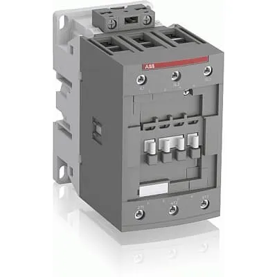
ABB 1SBL397001R1300 block contactor is engineered to safely switch motors in industrial control panels. In challenging networks, its wide coil voltage range and built‑in surge protection reduce nuisance trips and panel energy waste. It adheres to IEC/EN 60947-1 and 60947-4-1, UL 60335-2-40, and CSA standards, with coil protection IP20 and main terminals IP10. The compact AF technology enables a modular, easy‑to‑expand solution. With DIN rail mounting and compatible add‑on auxiliary blocks, it delivers reliable motor control while cutting installation time and total cost.
Product Information
Extended Description
1SBL397001R1300 ABB: The AF80-30-00-13 is a 3 pole - 1000 V IEC or 600 UL contactor with screw terminals, controlling motors up to 37 kW / 400 V AC (AC-3) or 60 hp / 480 V UL and switching power circuits up to 125 A (AC-1) or 105 A UL general use. Thanks to the AF technology, the contactor has a wide control voltage range (100-250 V 50/60 Hz and DC), managing large control voltage variations, reducing panel energy consumptions and ensuring distinct operations in unstable networks. Furthermore, surge protection is built-in, offering a compact solution. AF contactors have a block type design, can be easily extended with add-on auxiliary contact blocks and an additional wide range of accessories.
Minimum Order Quantity
1 piece
Customs Tariff Number
85364900
Data Sheet, Technical Information
1SBC100214C0202 - Main catalog Motor protection and control Manual motor starters, contactors and overload relays (PDF) - Edition 2024
Instructions and Manuals
Installation instructions AF(C)40(B)...96(B)-30 Contactors, CA4, CAL4, CAT4, CC4, LDC4 Accessories
Instructions and Manuals (Part 2)
Contactors and Overload relays guide
CAD Dimensional Drawing
Information - 2D and 3D files for CAD systems
Product Net Width
70 mm
Product Net Depth / Length
116 mm
Product Net Height
125.5 mm
Product Net Weight
1.17 kg
Number of Main Contacts NO
3
Number of Main Contacts NC
0
Number of Auxiliary Contacts NO
0
Number of Auxiliary Contacts NC
0
Number of Poles
3P
Standards
IEC/EN 60947-1, IEC/EN 60947-4-1, UL 60335-2-40 LZGH2 A2L, UL 60947-1, UL 60947-4-1, CSA C22.2 No. 60335-2-40 LZGH2 A2L, CSA C22.2 No. 60947-1:22, CSA C22.2 No. 60947-4-1:22
Rated Operational Voltage
Main Circuit 1000 V
Rated Frequency (f)
Control Circuit 50 / 60 Hz | Main Circuit 50 / 60 Hz
Conventional Free-air Thermal Current (Ith)
acc. to IEC 60947-4-1, Open Contactors Θ = 40 °C 130 A
Rated Operational Current AC-1 (Ie)
(690 V) 40 °C 125 A | (690 V) 60 °C 100 A | (690 V) 70 °C 85 A
Rated Operational Current AC-3 (Ie)
(415 V) 60 °C 80 A | (440 V) 60 °C 80 A | (500 V) 60 °C 65 A | (690 V) 60 °C 49 A | (1000 V) 60 °C 25 A | (380 / 400 V) 60 °C 80 A | (220 / 230 / 240 V) 60 °C 80 A
Rated Operational Current AC-3e (Ie)
(415 V) 60 °C 80 A | (440 V) 60 °C 80 A | (500 V) 60 °C 65 A | (690 V) 60 °C 49 A | (380 / 400 V) 60 °C 80 A | (220 / 230 / 240 V) 60 °C 80 A
Rated Operational Current DC-1 (Ie)
(110 V) 2 Poles in Series, 40 °C 125 A | (110 V) 2 Poles in Series, 60 °C 100 A | (110 V) 2 Poles in Series, 70 °C 85 A | (110 V) 3 Poles in Series, 40 °C 125 A | (110 V) 3 Poles in Series, 60 °C 100 A | (110 V) 3 Poles in Series, 70 °C 85 A | (220 V) 3 Poles in Series, 40 °C 125 A | (220 V) 3 Poles in Series, 60 °C 100 A | (220 V) 3 Poles in Series, 70 °C 85 A | (72 V) 1-Pole, 40 °C 125 A | (72 V) 1-Pole, 60 °C 100 A | (72 V) 1-Pole, 70 °C 85 A | (72 V) 2 Poles in Series, 40 °C 125 A | (72 V) 2 Poles in Series, 60 °C 100 A | (72 V) 2 Poles in Series, 70 °C 85 A | (72 V) 3 Poles in Series, 40 °C 125 A | (72 V) 3 Poles in Series, 60 °C 100 A | (72 V) 3 Poles in Series, 70 °C 85 A
Rated Operational Current DC-3 (Ie)
(110 V) 2 Poles in Series, 40 °C 125 A | (110 V) 2 Poles in Series, 60 °C 100 A | (110 V) 2 Poles in Series, 70 °C 85 A | (110 V) 3 Poles in Series, 40 °C 125 A | (110 V) 3 Poles in Series, 60 °C 100 A | (110 V) 3 Poles in Series, 70 °C 85 A | (220 V) 3 Poles in Series, 40 °C 125 A | (220 V) 3 Poles in Series, 60 °C 100 A | (220 V) 3 Poles in Series, 70 °C 85 A | (72 V) 1-Pole, 40 °C 125 A | (72 V) 1-Pole, 60 °C 100 A | (72 V) 1-Pole, 70 °C 85 A | (72 V) 2 Poles in Series, 40 °C 125 A | (72 V) 2 Poles in Series, 60 °C 100 A | (72 V) 2 Poles in Series, 70 °C 85 A | (72 V) 3 Poles in Series, 40 °C 125 A | (72 V) 3 Poles in Series, 60 °C 100 A | (72 V) 3 Poles in Series, 70 °C 85 A
Rated Operational Current DC-5 (Ie)
(110 V) 2 Poles in Series, 40 °C 125 A | (110 V) 2 Poles in Series, 60 °C 100 A | (110 V) 2 Poles in Series, 70 °C 85 A | (110 V) 3 Poles in Series, 40 °C 125 A | (110 V) 3 Poles in Series, 60 °C 100 A | (110 V) 3 Poles in Series, 70 °C 85 A | (220 V) 3 Poles in Series, 40 °C 125 A | (220 V) 3 Poles in Series, 60 °C 100 A | (220 V) 3 Poles in Series, 70 °C 85 A | (72 V) 1-Pole, 40 °C 125 A | (72 V) 1-Pole, 60 °C 100 A | (72 V) 1-Pole, 70 °C 85 A | (72 V) 2 Poles in Series, 40 °C 125 A | (72 V) 2 Poles in Series, 60 °C 100 A | (72 V) 2 Poles in Series, 70 °C 85 A | (72 V) 3 Poles in Series, 40 °C 125 A | (72 V) 3 Poles in Series, 60 °C 100 A | (72 V) 3 Poles in Series, 70 °C 85 A
Rated Operational Power AC-3 (Pe)
(400 V) 37 kW | (415 V) 45 kW | (440 V) 45 kW | (500 V) 45 kW | (690 V) 45 kW | (1000 V) 35 kW | (380 / 400 V) 37 kW | (220 / 230 / 240 V) 22 kW
Rated Operational Power AC-3e (Pe)
(415 V) 45 kW | (440 V) 45 kW | (500 V) 45 kW | (690 V) 45 kW | (380 / 400 V) 37 kW | (220 / 230 / 240 V) 22 kW
Rated Short-time Withstand Current Low Voltage (Icw)
at 40 °C Ambient Temp, in Free Air, from a Cold State 10 s 780 A | at 40 °C Ambient Temp, in Free Air, from a Cold State 15 min 140 A | at 40 °C Ambient Temp, in Free Air, from a Cold State 1 min 300 A | at 40 °C Ambient Temp, in Free Air, from a Cold State 1 s 1200 A | at 40 °C Ambient Temp, in Free Air, from a Cold State 30 s 450 A
Maximum Breaking Capacity
cos phi=0.45 (cos phi=0.35 for Ie > 100 A) at 440 V 1150 A | cos phi=0.45 (cos phi=0.35 for Ie > 100 A) at 690 V 750 A
Rated Insulation Voltage (Ui)
acc. to IEC 60947-4-1 1000 V | acc. to UL/CSA 600 V
Rated Impulse Withstand Voltage (Uimp)
8 kV
Maximum Electrical Switching Frequency
(AC-1) 600 cycles per hour | (AC-2 / AC-4) 150 cycles per hour | (AC-3) 1200 cycles per hour
Maximum Mechanical Switching Frequency
3600 cycles per hour
Rated Control Circuit Voltage (Uc)
50 Hz 100 ... 250 V | 60 Hz 100 ... 250 V | DC Operation 100 ... 250 V
Coil Consumption
Average Holding Value 50 / 60 Hz 4 V·A | Average Holding Value 50 Hz 4 V·A | Average Holding Value 60 Hz 4 V·A | Average Holding Value DC 2 W | Average Holding Value, from Warm State 2 W
Power Loss
at Rated Operating Conditions AC-1 per Pole 7.6 W | at Rated Operating Conditions AC-3 per Pole 3 W
Operate Time
Between Coil De-energization and NC Contact Closing 19 ... 105 ms | Between Coil De-energization and NO Contact Opening 17 ... 100 ms | Between Coil Energization and NC Contact Opening 38 ... 95 ms | Between Coil Energization and NO Contact Closing 42 ... 100 ms
Mounting on DIN Rail
TH35-15 (35 x 15 mm Mounting Rail) acc. to IEC 60715
Mounting by Screws (not supplied)
2 x M4 or 2 x M6 screws placed diagonally
Connecting Capacity Main Circuit
Flexible with Ferrule 1/2x 6 ... 50 mm² | Flexible with Insulated Ferrule 1/2x 6 ... 50 mm² | Rigid Stranded 1x 6 ... 70 mm² | Rigid Stranded 2x 6 ... 50 mm²
Connecting Capacity Control Circuit
Flexible with Ferrule 1/2x 0.75 ... 2.5 mm² | Flexible with Insulated Ferrule 1x 0.75 ... 2.5 mm² | Flexible with Insulated Ferrule 2x 0.75 ... 1.5 mm² | Rigid Solid 1/2x 1 ... 2.5 mm² | Rigid Stranded 1/2x 1 ... 2.5 mm²
Wire Stripping Length
Control Circuit 10 mm | Main Circuit 17 mm
Degree of Protection
acc. to IEC 60529, IEC 60947-1, EN 60529 Coil Terminals IP20 | acc. to IEC 60529, IEC 60947-1, EN 60529 Main Terminals IP10
Recommended Screw Driver
Pozidriv PZ
Tightening Torque
Control Circuit 1.2 N·m | Main Circuit 6 N·m
Terminal Type
Screw Terminals
Product Name
Block Contactor
NEMA Size
3
Continuous Current Rating NEMA
90 A
Horsepower Rating NEMA
(200 V AC) Three Phase 25 Hp | (230 V AC) Three Phase 30 Hp | (460 V AC) Three Phase 50 Hp | (575 V AC) Three Phase 50 Hp
Maximum Operating Voltage UL/CSA
Main Circuit 600 V
General Use Rating UL/CSA
(600 V AC) 105 A
Horsepower Rating UL/CSA
(120 V AC) Single Phase 7-1/2 hp | (200 ... 208 V AC) Three Phase 25 hp | (220 ... 240 V AC) Three Phase 30 hp | (240 V AC) Single Phase 15 hp | (440 ... 480 V AC) Three Phase 60 hp | (550 ... 600 V AC) Three Phase 75 hp
Connecting Capacity Main Circuit UL/CSA
Rigid Stranded 1/2x 6-1 AWG
Connecting Capacity Control Circuit UL/CSA
Rigid Solid 1/2x 18-14 AWG | Rigid Stranded 1/2x 18-14 AWG
Tightening Torque UL/CSA
Control Circuit 11 in·lb | Main Circuit 53 in·lb
Full Load Amps Motor Use
(120 V AC) Single Phase 80 A | (200 ... 208 V AC) Three Phase 78.2 A | (220 ... 240 V AC) Three Phase 80 A | (240 V AC) Single Phase 68 A | (440 ... 480 V AC) Three Phase 77 A | (550 ... 600 V AC) Three Phase 77 A
Ambient Air Temperature
Close to Contactor Fitted with Thermal O/L Relay -40 ... 70 °C | Close to Contactor without Thermal O/L Relay -40 ... 70 °C | Close to Contactor for Storage -60 ... +80 °C
Climatic Withstand
Category B according to IEC 60947-1 Annex Q
Maximum Operating Altitude Permissible
Without Derating 3000 m
Resistance to Shock acc. to IEC 60068-2-27
Closed, Shock Direction: A 25 g | Closed, Shock Direction: B1 25 g | Closed, Shock Direction: B2 15 g | Closed, Shock Direction: C1 25 g | Closed, Shock Direction: C2 25 g | Open, Shock Direction: B1 5 g
Resistance to Vibrations
3g Closed Position & 3g Open Position 5 ... 300 Hz
Pollution Degree
3
Conflict Minerals Reporting Template (CMRT)
CMRT - Conflict Minerals Reporting Template
REACH Declaration
REACH - Letter of Confirmation for block contactors, contactor relays, installation contactors, mini contactors, mini contactor relays, thermal overload relays, electronic overload relays and related accessories
RoHS Information
RoHS II declaration for block contactors, installation contactors, mini contactors, mini contactor relays, thermal overload relays, electronic overload relays and related accessories
RoHS Status
Following EU Directive 2011/65/EU and Amendment 2015/863 July 22, 2019
SCIP
2d5965a6-5b05-4e83-9459-9b5d78318aa2 France (FR)
Simplified SCIP
57ec6da0-6b74-4d41-942c-28c569726642 Poland (PL) | 5d3a40e2-0dd2-48f8-ae60-df6cfd6688b6 Belgium (BE) | 84e38467-b47e-41a7-a633-0e291c7314f6 Hungary (HU) | dacab1dc-889c-43ea-957a-0278e2eb9308 Bulgaria (BG) | 9bd00c9e-233b-4130-8db2-5b4e46325892 Hungary (HU) | 05d34ee2-b106-4e9e-8aaf-bb3c0696dab1 Belgium (BE) | b8f41cb2-309c-4bca-b0f8-31c8411b3c2d Italy (IT) | 73f32aa1-94bb-4e00-9ed0-49dd4c1836be Germany (DE) | f43cd794-f0d3-407d-a0c2-2e1624bd39f8 Netherlands (NL) | f6d0f85a-81dc-4d65-a3b8-a6c580818d49 Greece (GR) | b5f1e100-759a-4cac-9740-c5ad3386a78c Finland (FI) | 0bc3bb53-fcd8-496e-bf2c-4988d9b5f9e5 Sweden (SE) | 98c08dc1-2723-4141-a883-43d88a9c1f8e Poland (PL) | 4186d146-0fba-45da-a4c2-c87d50cbf7f1 Germany (DE) | 3115cc1f-b1ba-44a5-a504-88ff86c3be36 Spain (ES) | cbacee52-8d3e-4f4d-b9c8-53847a4f9923 Sweden (SE) | e2e8ca03-6811-4164-a875-294c3d170711 Norway (NO) | 64bf0ced-9457-40a7-8fb3-ad748bb21388 Croatia (HR) | f12fcaa6-7e48-48c3-8dae-bce6dc6370f1 Portugal (PT) | ba370118-f149-4c18-a5b4-98ddd3a0e2ee Germany (DE) | 72f40100-060e-4ff9-b571-06ff58ce4bfe Denmark (DK) | 32d40bf1-bae3-4434-bfe4-6d33f50f23d0 Germany (DE) | 4d8bf81b-1918-4230-bc72-81d884b83cc7 Czech Republic (CZ) | 5061ae4c-ad66-4a1a-8bea-d068495ba286 Poland (PL) | c60693b3-55d4-45d9-a28b-032cb87a11b0 Estonia (EE) | 0b815038-d3f8-47af-b03c-1494f6049fce Germany (DE) | 87ca08be-a7de-4803-890e-63cdc6854bbf France (FR)
Toxic Substances Control Act - TSCA
Toxic Substances Control Act (TSCA) declaration for Contactors
WEEE B2C / B2B
Business To Business
WEEE Category
5. Small Equipment (No External Dimension More Than 50 cm)
ABB EcoSolutions
Yes
End Of Life Disassembling Instructions
End of life instruction AF(S)40/52/65/80/96(B)(RT) Contactors
Environmental Product Declaration - EPD
Environmental Product Declaration AF80, AF96 (CN) Contactors | Environmental Product Declaration AF(S)80(B), AF(S)96(B) (FR)
Sustainable Material Content in Packaging (wt. %)
FSC Recycled Paper - 94.6 %
Sustainable Material Content in Product (wt. %)
Recycled Metal - 28.2 %
A2L Certificate – UL
UL-US Certificate of Compliance AF40 ... AF96 3-pole contactors - UL 60335-2-40 Household and Similar Electrical Appliances - Safety - Part 2-40: Particular Requirements for Electrical Heat Pumps, Air-Conditioners and Dehumidifiers | UL-CA Certificate of Compliance AF40 ... AF96 3-pole contactors - CSA C22.2 No. 60335-2-40 Household and Similar Electrical Appliances - Safety - Part 2-40: Particular Requirements for Electrical Heat Pumps, Air-Conditioners and Dehumidifiers
ABS Certificate
ABS Certificate, AF(S)09 to AF(S)96 contactors, NF contactor relays and CA4, CC4, CAL4, CAT4 auxiliary contact blocks, TEF4 electronic timers
BV Certificate
BV_2634H36994B1
CB Certificate
CB Certificate AF(S)80(B), AF(S)96(B) 3 and 4-pole contactors
CCC Certificate
CQC Certificate, AC Contactor, AF(S)*80-30-**-**, AF80-40-**-**, AF80-22-**-**, AF(S)96-30-**-**, Made in France
Declaration of Conformity - CCC
CCC Declaration of Conformity, AC Contactor, AF*80-30-**-**, AF80-40-**-**, AF80-22-**-**, AF*96-30-**-**, Made in France
Declaration of Conformity - CE
EU Declaration of Conformity AF09... AF96-30-.., AF09...38(Z)-30..K 3-pole Contactors
Declaration of Conformity - UKCA
UK Declaration of Conformity AF09... AF96-30-.., AF09...38(Z)-30..K 3-pole Contactors
DNV Certificate
DNV Certificate AF(S)09...96 3-pole & AF09...80 4-pole contactors with screw, spring, push-in terminals
KC Certificate
KC Certificate AF80, AF96 3-pole Contactors
LR Certificate
LRS Certificate AF(S)09..(K) ... AF96 3 and 4-pole contactors and CA(L)4..(K), CAT4, CC4 auxiliary contact blocks
RINA Certificate
Rina Certificate for AF09...AF96 contactors, NF contactor relays and accessories, screw and spring terminals
RMRS Certificate
RMRS Certificate AF(S)09(S)...AF(S)38 3-pole and 4-pole, AF(S)40..96 3-pole contactors with screw, push-in and spring terminals
UL Certificate
UL-US-L312527-1141-10303102-9 | UL-CA-L312527-4141-10303102-9
UL Listing Card
UL_E312527
Package Level 1 Units
box 1 piece
Package Level 1 Width
150 mm
Package Level 1 Depth / Length
150 mm
Package Level 1 Height
103 mm
Package Level 1 Gross Weight
1.29 kg
Package Level 1 EAN
3471523132931
Package Level 2 Units
box 8 piece
Package Level 2 Width
250 mm
Package Level 2 Depth / Length
300 mm
Package Level 2 Height
300 mm
Package Level 2 Gross Weight
10.32 kg
Package Level 3 Units
192 piece
Object Classification Code
Q
ETIM 7
EC000066 - Power contactor, AC switching
ETIM 8
EC000066 - Power contactor, AC switching
ETIM 9
EC000066 - Power contactor, AC switching
eClass
V11.0 : 27371003
UNSPSC
39121529
IDEA Granular Category Code (IGCC)
4758 >> Iec Contactors
E-Number (Finland)
3707122
E-Number (Sweden)
3210053
Feature AF technology with a wide control voltage range of 100–250 V AC/60 Hz and DC core voltage. Business Impact This tolerance minimizes control voltage fluctuations, enabling stable operation and reduced energy waste in power‑dense panels. Application Motor control circuits in automation lines that experience voltage swings. Feature 3‑pole design with 1000 V rated main circuit and current ratings up to 125 A AC‑1 and 80 A AC‑3. Business Impact Enables reliable motor starting and switching for standard industrial motors up to around 37 kW at higher voltages, improving line uptime. Application Control panels for pumps, fans, and conveyors. Feature Built‑in surge protection. Business Impact Protects downstream electronics and minimizes nuisance faults, extending panel life and reducing maintenance costs. Application Starter cabinets and machine controls in harsh electrical environments. Feature Coil consumption and power loss data (4 V·A holding, 7.6 W AC‑1 per pole, 3 W AC‑3 per pole). Business Impact Lower running energy and reduced heat in enclosures, contributing to energy efficiency and cooler panel environments. Application High‑duty cycle machines in continuous operation. Feature Compact footprint (70 mm width, 116 mm depth, 125.5 mm height) with IP20 coil and IP10 main terminals. Business Impact Space savings in modular panels, easier wiring, and simplified maintenance. Application New installations and upgrades in compact control cabinets. Feature DIN rail mounting TH35‑15 and compatibility with add‑on auxiliary contact blocks. Business Impact Rapid installation, scalable control architectures, and simplified expansion without rework. Application Panel builders upgrading to modular control blocks. Feature Flexible connection capacities: Main Circuit 1/2x 6–50 mm²; Control Circuit 0.75–2.5 mm²; long wire stripping length 10–17 mm. Business Impact Flexible wiring and faster commissioning, reducing installation time and labor costs. Application Heavy motor feeds and control circuits in machine controls.
Get a Quick Quote for a ABB 1SBL397001R1300
Chat with us on WhatsApp - fast responses guaranteed
Need to speak with someone? We'll call you back within 2 hours during business hours
Interested in ABB 1SBL397001R1300?
Enquire Now
FAQs
The unit supports DIN rail mounting on TH35-15 rails per IEC 60715, plus a panel-m mounting option using two M4 or M6 screws diagonally. This dual approach lets you optimize space in compact control cabinets while ensuring secure operation in vibration-prone environments.
The coil accepts 100–250 V across 50/60 Hz AC and DC operation, with coil holding values around 4 V·A. Control circuit wiring supports ferrules from 0.75 to 2.5 mm², while main circuit terminals accommodate 6–50 mm² flexible or rigid conductors, enabling flexible, code-compliant panel wiring.
Yes. It provides AC-3 ratings up to 80 A at 690 V and 65 A at 500 V, with 37 kW achievable on the 400–415 V side depending on configuration. This makes it appropriate for controlling medium to large motors in typical industrial drives and conveyors.
It complies with IEC/EN 60947‑1 and 60947‑4‑1, UL 60335‑2‑40, and CSA equivalents, plus related CE/UKCA declarations. The device also features an 8 kV impulse withstand and IP20 coil protection with IP10 main terminals, supporting safe operation in commercial and industrial environments.
AF technology delivers a wide coil voltage range that tolerates supply variations, reducing misoperation and energy waste. Built‑in surge protection lowers fault rates, while the modular design and DIN‑rail compatibility simplify installation and future expansion, reducing downtime and spare parts cost over the product lifecycle.