ABB AF80-30-11-14 Contactor - 1000V AF surge protection
Part Number: 1SBL397001R1411
Quick Summary
ABB AF80-30-11-14 Contactor enables robust motor control for industrial applications. In networks with voltage variation, standard contactors trip or chatter; AF technology tolerates 250–500 V and DC controls, reducing nuisance trips and improving reliability. It aligns with IEC/EN 60947-1 and 60947-4-1, UL 60335-2-40, and CE/UKCA declarations, supporting cross-border deployments across sites. The compact, DIN-rail friendly design integrates easily with add-on auxiliary contact blocks and a broad accessories portfolio, simplifying panel layouts, reducing wiring complexity, and speeding installation. All told, this translates to lower total cost of ownership and higher uptime on production lines and process facilities.
Product Information
Extended Description
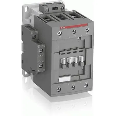
1SBL397001R1411 ABB: The AF80-30-11-14 is a 3 pole - 1000 V IEC or 600 UL contactor with pre-mounted auxiliary contacts and screw terminals, controlling motors up to 37 kW / 400 V AC (AC-3) or 60 hp / 480 V UL and switching power circuits up to 125 A (AC-1) or 105 A UL general use. Thanks to the AF technology, the contactor has a wide control voltage range (250-500 V 50/60 Hz and DC), managing large control voltage variations, reducing panel energy consumptions and ensuring distinct operations in unstable networks. Furthermore, surge protection is built-in, offering a compact solution. AF contactors have a block type design, can be easily extended with add-on auxiliary contact blocks and an additional wide range of accessories.
Minimum Order Quantity
1 piece
Customs Tariff Number
85364900
Data Sheet, Technical Information
1SBC100214C0202 - Main catalog Motor protection and control Manual motor starters, contactors and overload relays (PDF) - Edition 2024
Instructions and Manuals
Installation instructions AF(C)40(B)...96(B)-30 Contactors, CA4, CAL4, CAT4, CC4, LDC4 Accessories
Instructions and Manuals (Part 2)
Contactors and Overload relays guide
CAD Dimensional Drawing
Information - 2D and 3D files for CAD systems
Product Net Width
82 mm
Product Net Depth / Length
116 mm
Product Net Height
125.5 mm
Product Net Weight
1.21 kg
Number of Main Contacts NO
3
Number of Main Contacts NC
0
Number of Auxiliary Contacts NO
1
Number of Auxiliary Contacts NC
1
Number of Poles
3P
Standards
IEC/EN 60947-1, IEC/EN 60947-4-1, UL 60335-2-40 LZGH2 A2L, UL 60947-1, UL 60947-4-1, CSA C22.2 No. 60335-2-40 LZGH2 A2L, CSA C22.2 No. 60947-1:22, CSA C22.2 No. 60947-4-1:22
Rated Operational Voltage
Auxiliary Circuit 690 V | Main Circuit 1000 V
Rated Frequency (f)
Auxiliary Circuit 50 / 60 Hz | Control Circuit 50 / 60 Hz | Main Circuit 50 / 60 Hz
Conventional Free-air Thermal Current (Ith)
acc. to IEC 60947-4-1, Open Contactors Θ = 40 °C 130 A | acc. to IEC 60947-5-1, Θ = 40 °C 16 A
Rated Operational Current AC-1 (Ie)
(690 V) 40 °C 125 A | (690 V) 60 °C 100 A | (690 V) 70 °C 85 A
Rated Operational Current AC-3 (Ie)
(415 V) 60 °C 80 A | (440 V) 60 °C 80 A | (500 V) 60 °C 65 A | (690 V) 60 °C 49 A | (1000 V) 60 °C 25 A | (380 / 400 V) 60 °C 80 A | (220 / 230 / 240 V) 60 °C 80 A
Rated Operational Current AC-3e (Ie)
(415 V) 60 °C 80 A | (440 V) 60 °C 80 A | (500 V) 60 °C 65 A | (690 V) 60 °C 49 A | (380 / 400 V) 60 °C 80 A | (220 / 230 / 240 V) 60 °C 80 A
Rated Operational Current AC-15 (Ie)
(500 V) 2 A | (690 V) 2 A | (24 / 127 V) 6 A | (220 / 240 V) 4 A | (400 / 440 V) 3 A
Rated Operational Current DC-1 (Ie)
(110 V) 2 Poles in Series, 40 °C 125 A | (110 V) 2 Poles in Series, 60 °C 100 A | (110 V) 2 Poles in Series, 70 °C 85 A | (110 V) 3 Poles in Series, 40 °C 125 A | (110 V) 3 Poles in Series, 60 °C 100 A | (110 V) 3 Poles in Series, 70 °C 85 A | (220 V) 3 Poles in Series, 40 °C 125 A | (220 V) 3 Poles in Series, 60 °C 100 A | (220 V) 3 Poles in Series, 70 °C 85 A | (72 V) 1-Pole, 40 °C 125 A | (72 V) 1-Pole, 60 °C 100 A | (72 V) 1-Pole, 70 °C 85 A | (72 V) 2 Poles in Series, 40 °C 125 A | (72 V) 2 Poles in Series, 60 °C 100 A | (72 V) 2 Poles in Series, 70 °C 85 A | (72 V) 3 Poles in Series, 40 °C 125 A | (72 V) 3 Poles in Series, 60 °C 100 A | (72 V) 3 Poles in Series, 70 °C 85 A
Rated Operational Current DC-3 (Ie)
(110 V) 2 Poles in Series, 40 °C 125 A | (110 V) 2 Poles in Series, 60 °C 100 A | (110 V) 2 Poles in Series, 70 °C 85 A | (110 V) 3 Poles in Series, 40 °C 125 A | (110 V) 3 Poles in Series, 60 °C 100 A | (110 V) 3 Poles in Series, 70 °C 85 A | (220 V) 3 Poles in Series, 40 °C 125 A | (220 V) 3 Poles in Series, 60 °C 100 A | (220 V) 3 Poles in Series, 70 °C 85 A | (72 V) 1-Pole, 40 °C 125 A | (72 V) 1-Pole, 60 °C 100 A | (72 V) 1-Pole, 70 °C 85 A | (72 V) 2 Poles in Series, 40 °C 125 A | (72 V) 2 Poles in Series, 60 °C 100 A | (72 V) 2 Poles in Series, 70 °C 85 A | (72 V) 3 Poles in Series, 40 °C 125 A | (72 V) 3 Poles in Series, 60 °C 100 A | (72 V) 3 Poles in Series, 70 °C 85 A
Rated Operational Current DC-5 (Ie)
(110 V) 2 Poles in Series, 40 °C 125 A | (110 V) 2 Poles in Series, 60 °C 100 A | (110 V) 2 Poles in Series, 70 °C 85 A | (110 V) 3 Poles in Series, 40 °C 125 A | (110 V) 3 Poles in Series, 60 °C 100 A | (110 V) 3 Poles in Series, 70 °C 85 A | (220 V) 3 Poles in Series, 40 °C 125 A | (220 V) 3 Poles in Series, 60 °C 100 A | (220 V) 3 Poles in Series, 70 °C 85 A | (72 V) 1-Pole, 40 °C 125 A | (72 V) 1-Pole, 60 °C 100 A | (72 V) 1-Pole, 70 °C 85 A | (72 V) 2 Poles in Series, 40 °C 125 A | (72 V) 2 Poles in Series, 60 °C 100 A | (72 V) 2 Poles in Series, 70 °C 85 A | (72 V) 3 Poles in Series, 40 °C 125 A | (72 V) 3 Poles in Series, 60 °C 100 A | (72 V) 3 Poles in Series, 70 °C 85 A
Rated Operational Current DC-13 (Ie)
(24 V) 6 A / 144 W | (48 V) 2.8 A / 134 W | (72 V) 1 A / 72 W | (110 V) 0.55 A / 60 W | (125 V) 0.55 A / 69 W | (220 V) 0.27 A / 60 W | (250 V) 0.27 A / 68 W | (400 V) 0.15 A / 60 W | (500 V) 0.13 A / 65 W | (600 V) 0.1 A / 60 W
Rated Operational Power AC-3 (Pe)
(400 V) 37 kW | (415 V) 45 kW | (440 V) 45 kW | (500 V) 45 kW | (690 V) 45 kW | (1000 V) 35 kW | (380 / 400 V) 37 kW | (220 / 230 / 240 V) 22 kW
Rated Operational Power AC-3e (Pe)
(415 V) 45 kW | (440 V) 45 kW | (500 V) 45 kW | (690 V) 45 kW | (380 / 400 V) 37 kW | (220 / 230 / 240 V) 22 kW
Rated Short-time Withstand Current Low Voltage (Icw)
at 40 °C Ambient Temp, in Free Air, from a Cold State 10 s 780 A | at 40 °C Ambient Temp, in Free Air, from a Cold State 15 min 140 A | at 40 °C Ambient Temp, in Free Air, from a Cold State 1 min 300 A | at 40 °C Ambient Temp, in Free Air, from a Cold State 1 s 1200 A | at 40 °C Ambient Temp, in Free Air, from a Cold State 30 s 450 A | for 0.1 s 140 A | for 1 s 100 A
Maximum Breaking Capacity
cos phi=0.45 (cos phi=0.35 for Ie > 100 A) at 440 V 1150 A | cos phi=0.45 (cos phi=0.35 for Ie > 100 A) at 690 V 750 A
Rated Insulation Voltage (Ui)
acc. to IEC 60947-4-1 1000 V | acc. to IEC 60947-5-1 690 V | acc. to UL/CSA 600 V
Rated Impulse Withstand Voltage (Uimp)
8 kV
Maximum Electrical Switching Frequency
(AC-1) 600 cycles per hour | (AC-15) 1200 cycles per hour | (AC-2 / AC-4) 150 cycles per hour | (AC-3) 1200 cycles per hour | (DC-13) 900 cycles per hour
Maximum Mechanical Switching Frequency
3600 cycles per hour
Rated Control Circuit Voltage (Uc)
50 Hz 250 ... 500 V | 60 Hz 250 ... 500 V | DC Operation 250 ... 500 V
Coil Consumption
Average Holding Value 50 / 60 Hz 4 V·A | Average Holding Value 50 Hz 4 V·A | Average Holding Value 60 Hz 4 V·A | Average Holding Value DC 2 W | Average Holding Value, from Warm State 2 W
Power Loss
at 6 A per Pole 0.1 W | at Rated Operating Conditions AC-1 per Pole 7.6 W | at Rated Operating Conditions AC-3 per Pole 3 W
Operate Time
Between Coil De-energization and NC Contact Closing 19 ... 105 ms | Between Coil De-energization and NO Contact Opening 17 ... 100 ms | Between Coil Energization and NC Contact Opening 38 ... 95 ms | Between Coil Energization and NO Contact Closing 42 ... 100 ms
Mounting on DIN Rail
TH35-15 (35 x 15 mm Mounting Rail) acc. to IEC 60715
Mounting by Screws (not supplied)
2 x M4 or 2 x M6 screws placed diagonally
Connecting Capacity Main Circuit
Flexible with Ferrule 1/2x 6 ... 50 mm² | Flexible with Insulated Ferrule 1/2x 6 ... 50 mm² | Rigid Stranded 1x 6 ... 70 mm² | Rigid Stranded 2x 6 ... 50 mm²
Connecting Capacity Auxiliary Circuit
Flexible with Ferrule 1/2x 0.75 ... 2.5 mm² | Flexible with Insulated Ferrule 2x 0.75 ... 1.5 mm² | Flexible with Insulated Ferrule 1x 0.75 ... 2.5 mm² | Rigid 1/2x 1 ... 2.5 mm²
Connecting Capacity Control Circuit
Flexible with Ferrule 1/2x 0.75 ... 2.5 mm² | Flexible with Insulated Ferrule 1x 0.75 ... 2.5 mm² | Flexible with Insulated Ferrule 2x 0.75 ... 1.5 mm² | Rigid 1/2x 1 ... 2.5 mm²
Wire Stripping Length
Auxiliary Circuit 10 mm | Control Circuit 10 mm | Main Circuit 17 mm
Degree of Protection
acc. to IEC 60529, IEC 60947-1, EN 60529 Auxiliary Terminals IP20 | acc. to IEC 60529, IEC 60947-1, EN 60529 Coil Terminals IP20 | acc. to IEC 60529, IEC 60947-1, EN 60529 Main Terminals IP10
Recommended Screw Driver
Pozidriv PZ
Tightening Torque
Auxiliary Circuit 1.2 N·m | Control Circuit 1.2 N·m | Main Circuit 6 N·m
Terminal Type
Screw Terminals
Product Name
Block Contactor
NEMA Size
3
Continuous Current Rating NEMA
90 A
Horsepower Rating NEMA
(200 V AC) Three Phase 25 Hp | (230 V AC) Three Phase 30 Hp | (460 V AC) Three Phase 50 Hp | (575 V AC) Three Phase 50 Hp
Maximum Operating Voltage UL/CSA
Main Circuit 600 V
General Use Rating UL/CSA
(600 V AC) 105 A
Horsepower Rating UL/CSA
(120 V AC) Single Phase 7-1/2 hp | (200 ... 208 V AC) Three Phase 25 hp | (220 ... 240 V AC) Three Phase 30 hp | (240 V AC) Single Phase 15 hp | (440 ... 480 V AC) Three Phase 60 hp | (550 ... 600 V AC) Three Phase 75 hp
Connecting Capacity Main Circuit UL/CSA
Rigid Stranded 1/2x 6-1 AWG
Tightening Torque UL/CSA
Auxiliary Circuit 11 in·lb | Control Circuit 11 in·lb | Main Circuit 53 in·lb
Full Load Amps Motor Use
(120 V AC) Single Phase 80 A | (200 ... 208 V AC) Three Phase 78.2 A | (220 ... 240 V AC) Three Phase 80 A | (240 V AC) Single Phase 68 A | (440 ... 480 V AC) Three Phase 77 A | (550 ... 600 V AC) Three Phase 77 A
Ambient Air Temperature
Close to Contactor Fitted with Thermal O/L Relay -40 ... 70 °C | Close to Contactor without Thermal O/L Relay -40 ... 70 °C | Close to Contactor for Storage -60 ... +80 °C
Climatic Withstand
Category B according to IEC 60947-1 Annex Q
Maximum Operating Altitude Permissible
Without Derating 3000 m
Resistance to Shock acc. to IEC 60068-2-27
Closed, Shock Direction: A 25 g | Closed, Shock Direction: B1 25 g | Closed, Shock Direction: B2 15 g | Closed, Shock Direction: C1 25 g | Closed, Shock Direction: C2 25 g | Open, Shock Direction: B1 5 g
Resistance to Vibrations
3g Closed Position & 3g Open Position 5 ... 300 Hz
Pollution Degree
3
Conflict Minerals Reporting Template (CMRT)
CMRT - Conflict Minerals Reporting Template
REACH Declaration
REACH - Letter of Confirmation for block contactors, contactor relays, installation contactors, mini contactors, mini contactor relays, thermal overload relays, electronic overload relays and related accessories
RoHS Information
RoHS II declaration for block contactors, installation contactors, mini contactors, mini contactor relays, thermal overload relays, electronic overload relays and related accessories
RoHS Status
Following EU Directive 2011/65/EU and Amendment 2015/863 July 22, 2019
SCIP
46fb74f0-9249-4510-b965-32adc4df34a6 China (CN)
Simplified SCIP
73318c33-1fd5-43d6-81fc-9c4129feb37f Spain (ES) | 44295554-0c0d-4746-b12d-974d50c9bad1 Croatia (HR) | f629448b-87af-4ebf-9ebb-a9c169e31a9c Germany (DE) | 2f61ca60-e87b-4741-9a17-af22da8310f3 Czech Republic (CZ) | cf27b50a-abba-4809-839e-fc0b711cfdb3 Belgium (BE) | 9aa6fac2-529d-4798-81d0-578f8ea17b72 Poland (PL) | 0d71f139-ac6e-497d-ad35-ea0bd60eb97e Poland (PL) | 2d4286d3-5e5a-411d-ac14-6899d3bb2501 Netherlands (NL) | 49ee62bc-138b-4f3e-b8c9-71eeb1e06bd9 Hungary (HU) | d2194e0e-1aeb-40ec-aac8-75fe2c485593 Norway (NO) | 95ce7616-64ce-407a-a374-7d3d28a7a6fd Hungary (HU) | 96ee6796-13ed-426b-bf55-5d8041ed1247 Bulgaria (BG) | 3e9b070c-baa5-485e-a641-ee8db7d6e9aa Estonia (EE) | 375e9d9f-d96a-44b0-9c2d-812e48ddfea0 Finland (FI) | 21d948ed-0970-44ba-aad8-5f837449f29d Belgium (BE) | d4393a5d-6e45-4d54-b41a-ca2a4b0ec5cf Germany (DE) | d20d1e86-1296-4c2e-9b71-5fcc08b3574d Greece (GR) | 87ed63f7-d09b-4e15-9875-048859bc7fa6 Portugal (PT) | 56262a90-44b9-4b9f-b4ee-6b4ba530a367 Sweden (SE) | 9c6ca105-00fd-44f1-aaa3-9cc5af377d98 Germany (DE) | 3c6516af-19be-48f2-aad5-7d4121185a4f Poland (PL) | d545b85e-0bb2-4623-ac44-64c491525217 Germany (DE) | 78b7ff92-0b77-45e8-8d33-f2840613a70e Denmark (DK) | 269e7978-514d-4f2c-b944-236bb01ff5cf France (FR) | 357c9100-05eb-4e64-a369-4203a24603da France (FR) | da43b730-7cba-4442-95da-9aaf88c1d963 Sweden (SE) | f9f25caa-fcec-4b4c-81b0-8f3a745c29bc Germany (DE)
Toxic Substances Control Act - TSCA
Toxic Substances Control Act (TSCA) declaration for Contactors
WEEE B2C / B2B
Business To Business
WEEE Category
5. Small Equipment (No External Dimension More Than 50 cm)
ABB EcoSolutions
Yes
End Of Life Disassembling Instructions
End of life instruction AF(S)40/52/65/80/96(B)(RT) Contactors
Environmental Product Declaration - EPD
Environmental Product Declaration AF80, AF96 (CN) Contactors | Environmental Product Declaration AF(S)80(B), AF(S)96(B) (FR)
Sustainable Material Content in Packaging (wt. %)
FSC Recycled Paper - 94.6 %
Sustainable Material Content in Product (wt. %)
Recycled Metal - 28.2 %
A2L Certificate – UL
UL-US Certificate of Compliance AF40 ... AF96 3-pole contactors - UL 60335-2-40 Household and Similar Electrical Appliances - Safety - Part 2-40: Particular Requirements for Electrical Heat Pumps, Air-Conditioners and Dehumidifiers | UL-CA Certificate of Compliance AF40 ... AF96 3-pole contactors - CSA C22.2 No. 60335-2-40 Household and Similar Electrical Appliances - Safety - Part 2-40: Particular Requirements for Electrical Heat Pumps, Air-Conditioners and Dehumidifiers
ABS Certificate
ABS Certificate, AF(S)09 to AF(S)96 contactors, NF contactor relays and CA4, CC4, CAL4, CAT4 auxiliary contact blocks, TEF4 electronic timers
BV Certificate
BV_2634H36994B1
CB Certificate
CB Certificate AF(S)80(B), AF(S)96(B) 3 and 4-pole contactors
CCC Certificate
CQC Certificate, AC Contactor, AF(S)*80-30-**-**, AF80-40-**-**, AF80-22-**-**, AF(S)96-30-**-**, Made in France
Declaration of Conformity - CCC
CCC Declaration of Conformity, AC Contactor, AF*80-30-**-**, AF80-40-**-**, AF80-22-**-**, AF*96-30-**-**, Made in France
Declaration of Conformity - CE
EU Declaration of Conformity AF09... AF96-30-.., AF09...38(Z)-30..K 3-pole Contactors
Declaration of Conformity - UKCA
UK Declaration of Conformity AF09... AF96-30-.., AF09...38(Z)-30..K 3-pole Contactors
DNV Certificate
DNV Certificate AF(S)09...96 3-pole & AF09...80 4-pole contactors with screw, spring, push-in terminals
KC Certificate
KC Certificate AF80, AF96 3-pole Contactors
LR Certificate
LRS Certificate AF(S)09..(K) ... AF96 3 and 4-pole contactors and CA(L)4..(K), CAT4, CC4 auxiliary contact blocks
RINA Certificate
Rina Certificate for AF09...AF96 contactors, NF contactor relays and accessories, screw and spring terminals
RMRS Certificate
RMRS Certificate AF(S)09(S)...AF(S)38 3-pole and 4-pole, AF(S)40..96 3-pole contactors with screw, push-in and spring terminals
UL Certificate
UL-US-L312527-1141-10303102-9 | UL-CA-L312527-4141-10303102-9
UL Listing Card
UL_E312527
Package Level 1 Units
box 1 piece
Package Level 1 Width
150 mm
Package Level 1 Depth / Length
150 mm
Package Level 1 Height
103 mm
Package Level 1 Gross Weight
1.33 kg
Package Level 1 EAN
3471523133044
Package Level 2 Units
box 8 piece
Package Level 2 Width
250 mm
Package Level 2 Depth / Length
300 mm
Package Level 2 Height
300 mm
Package Level 2 Gross Weight
10.64 kg
Package Level 3 Units
192 piece
Object Classification Code
Q
ETIM 7
EC000066 - Power contactor, AC switching
ETIM 8
EC000066 - Power contactor, AC switching
ETIM 9
EC000066 - Power contactor, AC switching
eClass
V11.0 : 27371003
UNSPSC
39121529
IDEA Granular Category Code (IGCC)
4758 >> Iec Contactors
E-Number (Finland)
3707128
Feature AF technology provides a wide control voltage range of 250–500 V AC 50/60 Hz and DC, coupled with built-in surge protection. Business Impact The control circuitry remains stable despite supply fluctuations, reducing panel energy waste and preventing unexpected trips. Application This is ideal for manufacturing lines where mains voltage can swing, such as conveyors and pumps, delivering dependable motor control with fewer panel recalibrations. Feature Three-pole main contacts (NO) and auxiliary contacts (NO/NC) minimize discrete wiring. Business Impact A compact, integrated starter reduces bill of materials and installation time while preserving control circuit functionality. Application Suitable for compact motor starters requiring both main switching and control signaling in a single device. Feature 1000 V rated insulation for main circuit and 690 V for auxiliary circuit plus 50/60 Hz operation. Business Impact Higher insulation margin improves safety and reliability in demanding environments, enabling broader voltage compatibility. Application Fits larger, higher-voltage drives without custom solutions. Feature Built-in surge protection and compact block design with DIN-rail mounting. Business Impact Enhances system protection and saves panel space while enabling easy expansion with add-on blocks. Application Ideal for control cabinets in process plants and material handling systems. Feature DIN-rail mounting TH35-15 and screw terminal connections. Business Impact Simplifies installation and maintenance, reducing labor time and potential wiring faults. Application Common in factory automation panels and retrofit projects. Feature Robust mechanical and electrical life ratings (3600 cycles mechanical, up to 1200 cycles per hour electrically). Business Impact Improves lifecycle cost and reduces replacement frequency in high-demand applications. Application Suitable for continuous-duty service in packaging, pumping, and material handling systems. Feature Compact dimensions (82 mm width, 116 mm depth, 125.5 mm height) and 1.21 kg weight. Business Impact Saves enclosure space and allows denser panel layouts without compromising performance. Application Particularly beneficial in space-constrained control panels and retrofit installations. Feature IP20 coil protection and IP10 main terminals provide targeted protection for control wiring and main circuits. Business Impact Enhances safety and durability in typical factory environments. Application Supports reliable operation in harsh manufacturing settings. Feature Compliance with IEC/EN 60947-1, 60947-4-1; UL/CSA listings; CE/UKCA declarations. Business Impact Ensures regulatory conformity across global sites, easing procurement and qualification. Application Supports global rollouts and supplier reliability for industrial automation projects.
Get a Quick Quote for a ABB 1SBL397001R1411
Chat with us on WhatsApp - fast responses guaranteed
Need to speak with someone? We'll call you back within 2 hours during business hours
Interested in ABB 1SBL397001R1411?
Enquire Now
FAQs
The coil supports 250–500 V for 50/60 Hz AC operation and DC control, offering a wide tolerance to voltage variations and reducing tripping in unstable power networks.
Rated Operational Current AC-3 is up to 80 A at 415–440 V and up to 49 A at 690 V; AC-3e ratings and higher-voltage variants are provided, enabling compatible motor switching for mid-range industrial loads.
Yes, it is designed for TH35-15 DIN rail mounting. Main circuit uses screw terminals with flexible or rigid conductors, and auxiliary/control circuits use compatible screw terminals for easy wiring.
It complies with IEC/EN 60947-1 and 60947-4-1, UL 60335-2-40, and CSA equivalents, with CE and UKCA declarations, UL/CSA listings, and additional certifications listed in the product dossier.
Main circuit accepts flexible ferrule 1/2 x 6–50 mm2 or rigid/ flexible 1x/2x 6–70 mm2; auxiliary and control circuits accept flexible ferrule 0.75–2.5 mm2 or rigid 1/2 x 1–2.5 mm2, with 17 mm main wire stripping and 10 mm for auxiliary/control circuits.