ABB 1SBL397561R1400 Block Contactor - IEC/UL 60947-4-1
Part Number: 1SBL397561R1400
Quick Summary
The ABB AF80B block contactor is a 4P device that safely controls motors up to 37 kW in industrial panels and drives. Wide control voltage variations in unstable networks can cause nuisance trips and wasted energy, making robust coil performance essential. Meets IEC/EN 60947-4-1 and UL 60947-4-1 with CSA listings, and features coil terminals protected to IP20 while main terminals are IP10. This AF80B solution also aligns with DIN rail mounting and a broad accessory ecosystem, delivering practical value for streamlined panel design and scalable automation. The result is lower installation complexity and improved total cost of ownership for machine builders and system integrators.
Product Information
Extended Description
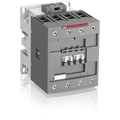
1SBL397561R1400 ABB: The AF80B-22-00-14 is a 4 pole - 1000 V IEC or 600 UL contactor with screw terminals, controlling motors up to 37 kW / 400 V AC (AC-3) and switching power circuits up to 125 A (AC-1) or 105 A UL general use. Thanks to the AF technology, the contactor has a wide control voltage range (250-500 V 50/60 Hz and DC), managing large control voltage variations, reducing panel energy consumptions and ensuring distinct operations in unstable networks. Furthermore, surge protection is built-in, offering a compact solution. AF contactors have a block type design, can be easily extended with add-on auxiliary contact blocks and an additional wide range of accessories.
Minimum Order Quantity
1 piece
Customs Tariff Number
85364900
Data Sheet, Technical Information
Motor control and protection for Rolling stock application_PDF
Instructions and Manuals
Installation instructions AF(C)40(B)...80(B)-40/22 Contactors, CA4, CAL4, CAT4, CC4, LDC4 Accessories
Instructions and Manuals (Part 2)
Contactors and Overload relays guide
CAD Dimensional Drawing
Information - 2D and 3D files for CAD systems
Product Net Width
90 mm
Product Net Depth / Length
116 mm
Product Net Height
125.5 mm
Product Net Weight
1.44 kg
Number of Main Contacts NO
2
Number of Main Contacts NC
2
Number of Auxiliary Contacts NO
0
Number of Auxiliary Contacts NC
0
Number of Poles
4P
Standards
IEC/EN 60947-1, IEC/EN 60947-4-1, UL 60947-1, UL 60947-4-1, CSA C22.2 No. 60947-1:22, CSA C22.2 No. 60947-4-1:22, IEC 60077-1 (applicable parts), IEC 60077-2 (applicable parts), EN 50155 (applicable parts), IEC 61373, For compliance confirmation on applicable parts based on your application and combination, please consult your ABB sales representatives.
Rated Operational Voltage
Main Circuit 1000 V
Rated Frequency (f)
Control Circuit 50 / 60 Hz | Main Circuit 50 / 60 Hz
Conventional Free-air Thermal Current (Ith)
acc. to IEC 60947-4-1, Open Contactors Θ = 40 °C 125 A
Rated Operational Current AC-1 (Ie)
(690 V) 40 °C 125 A | (690 V) 60 °C 105 A | (690 V) 70 °C 90 A
Rated Operational Current AC-3 (Ie)
(415 V) 60 °C 80 A | (440 V) 60 °C 80 A | (500 V) 60 °C 65 A | (690 V) 60 °C 49 A | (1000 V) 60 °C 25 A | (380 / 400 V) 60 °C 80 A | (220 / 230 / 240 V) 60 °C 80 A
Rated Operational Power AC-3 (Pe)
(415 V) 45 kW | (440 V) 45 kW | (500 V) 45 kW | (690 V) 45 kW | (1000 V) 35 kW | (380 / 400 V) 37 kW | (220 / 230 / 240 V) 22 kW
Rated Short-time Withstand Current Low Voltage (Icw)
at 40 °C Ambient Temp, in Free Air, from a Cold State 10 s 780 A | at 40 °C Ambient Temp, in Free Air, from a Cold State 15 min 140 A | at 40 °C Ambient Temp, in Free Air, from a Cold State 1 min 300 A | at 40 °C Ambient Temp, in Free Air, from a Cold State 1 s 1200 A | at 40 °C Ambient Temp, in Free Air, from a Cold State 30 s 450 A
Maximum Breaking Capacity
cos phi=0.45 (cos phi=0.35 for Ie > 100 A) at 440 V 1150 A | cos phi=0.45 (cos phi=0.35 for Ie > 100 A) at 690 V 750 A
Rated Insulation Voltage (Ui)
acc. to IEC 60947-4-1 1000 V | acc. to UL/CSA 600 V
Maximum Electrical Switching Frequency
(AC-1) 600 cycles per hour
Maximum Mechanical Switching Frequency
3600 cycles per hour
Rated Control Circuit Voltage (Uc)
50 Hz 250 ... 500 V | 60 Hz 250 ... 500 V | DC Operation 250 ... 500 V
Coil Consumption
Average Holding Value 50 / 60 Hz 4 V·A | Average Holding Value DC 2 W
Power Loss
at Rated Operating Conditions AC-1 per Pole 8 W | at Rated Operating Conditions AC-3 per Pole 3.2 W
Mounting on DIN Rail
TH35-15 (35 x 15 mm Mounting Rail) acc. to IEC 60715
Mounting by Screws (not supplied)
2 x M4 or 2 x M6 screws placed diagonally
Connecting Capacity Main Circuit
Flexible with Ferrule 1/2x 6 ... 50 mm² | Flexible with Insulated Ferrule 1/2x 6 ... 50 mm² | Rigid Stranded 1x 6 ... 70 mm² | Rigid Stranded 2x 6 ... 50 mm²
Connecting Capacity Control Circuit
Flexible with Ferrule 1/2x 0.75 ... 2.5 mm² | Flexible with Insulated Ferrule 1x 0.75 ... 2.5 mm² | Flexible with Insulated Ferrule 2x 0.75 ... 1.5 mm² | Rigid Solid 1/2x 1 ... 2.5 mm² | Rigid Stranded 1/2x 1 ... 2.5 mm²
Wire Stripping Length
Auxiliary Circuit 0 mm | Control Circuit 10 mm | Main Circuit 17 mm
Degree of Protection
acc. to IEC 60529, IEC 60947-1, EN 60529 Coil Terminals IP20 | acc. to IEC 60529, IEC 60947-1, EN 60529 Main Terminals IP10
Recommended Screw Driver
Pozidriv PZ
Tightening Torque
Control Circuit 1.2 N·m | Main Circuit 6 N·m
Terminal Type
Screw Terminals
Product Name
Block Contactor
Continuous Current Rating NEMA
0 A
Maximum Operating Voltage UL/CSA
Main Circuit 600 V
General Use Rating UL/CSA
(600 V AC) 105 A
Connecting Capacity Main Circuit UL/CSA
Rigid Stranded 1/2x 6-1 AWG
Connecting Capacity Control Circuit UL/CSA
Rigid Solid 1/2x 18-14 AWG | Rigid Stranded 1/2x 18-14 AWG
Tightening Torque UL/CSA
Control Circuit 11 in·lb | Main Circuit 53 in·lb
Ambient Air Temperature
Close to Contactor for Storage -60 ... +80 °C | Near Contactor for Operation in Free Air -40 ... 70 °C
Climatic Withstand
Category B according to IEC 60947-1 Annex Q
Maximum Operating Altitude Permissible
Without Derating 3000 m
Shock and Vibration Withstand acc. to IEC 61373
Category 1, Class B
Pollution Degree
3
REACH Declaration
REACH - Letter of Confirmation for block contactors, contactor relays, installation contactors, mini contactors, mini contactor relays, thermal overload relays, electronic overload relays and related accessories
RoHS Information
RoHS II declaration for block contactors, installation contactors, mini contactors, mini contactor relays, thermal overload relays, electronic overload relays and related accessories
RoHS Status
Following EU Directive 2011/65/EU and Amendment 2015/863 July 22, 2019
Toxic Substances Control Act - TSCA
Toxic Substances Control Act (TSCA) declaration for Contactors
WEEE B2C / B2B
Business To Business
WEEE Category
5. Small Equipment (No External Dimension More Than 50 cm)
ABB EcoSolutions
Yes
End Of Life Disassembling Instructions
End of life instruction AF(S)40/52/65/80/96(B)(RT) Contactors
Environmental Product Declaration - EPD
Environmental Product Declaration AF(S)80(B), AF(S)96(B) (FR)
Sustainable Material Content in Packaging (wt. %)
FSC Recycled Paper - 94.6 %
Sustainable Material Content in Product (wt. %)
Recycled Metal - 28.2 %
A2L Certificate – UL
UL-US Certificate of Compliance AF40 ... AF96 3-pole contactors - UL 60335-2-40 Household and Similar Electrical Appliances - Safety - Part 2-40: Particular Requirements for Electrical Heat Pumps, Air-Conditioners and Dehumidifiers | UL-CA Certificate of Compliance AF40 ... AF96 3-pole contactors - CSA C22.2 No. 60335-2-40 Household and Similar Electrical Appliances - Safety - Part 2-40: Particular Requirements for Electrical Heat Pumps, Air-Conditioners and Dehumidifiers
CB Certificate
CB Certificate AF(S)80(B), AF(S)96(B) 3 and 4-pole contactors
CCC Certificate
CQC Certificate, AC Contactor, AF(S)*80-30-**-**, AF80-40-**-**, AF80-22-**-**, AF(S)96-30-**-**, Made in France
Declaration of Conformity - CE
EU Declaration of Conformity AF09 ... AF38(Z)B..(K), AF40B ... AF96B 3 and 4-pole contactors
Declaration of Conformity - UKCA
UK Declaration of Conformity AF09 ... AF38(Z)B..(K), AF40B ... AF96B 3 and 4-pole contactors
UL Certificate
UL-US Certificate of Compliance AF40(B)...80(B) 4-pole contactors | UL-CA Certificate of Compliance AF40(B)...80(B) 4-pole contactors
Package Level 1 Units
box 1 piece
Package Level 1 Width
150 mm
Package Level 1 Depth / Length
150 mm
Package Level 1 Height
103 mm
Package Level 1 Gross Weight
1.57 kg
Package Level 1 EAN
3471523025486
Package Level 2 Units
box 8 piece
Package Level 2 Width
250 mm
Package Level 2 Depth / Length
300 mm
Package Level 2 Height
300 mm
Package Level 2 Gross Weight
12.56 kg
Object Classification Code
Q
ETIM 7
EC000066 - Power contactor, AC switching
ETIM 8
EC000066 - Power contactor, AC switching
ETIM 9
EC000066 - Power contactor, AC switching
eClass
V11.0 : 27371003
UNSPSC
39121529
Feature AF technology with a wide control voltage range and built-in surge protection → Business Impact Reduces energy waste and improves reliability in networks with voltage fluctuations → Application Motor control in process lines, conveyors, and packaging equipment. Feature Four-pole block design with screw terminals and accessible copper conductors → Business Impact Enables robust power switching up to 125 A AC-1 and up to 80 A AC-3 in many common voltages → Application Suitable for 380/400/415/440/500 V AC motor circuits in industrial panels. Feature Coil voltage range 250–500 V AC/60 Hz and DC → Business Impact Simplifies sourcing, lowers spare-part needs, and supports diverse control architectures → Application Integrates with existing control circuits without multiple coil variants. Feature Built-in surge protection and compact footprint → Business Impact Extends device life and reduces panel size, improving enclosure economics → Application Ideal for space-constrained control cabinets and safety-critical applications. Feature DIN rail mounting TH35-15 and provision for auxiliary contact blocks → Business Impact Fast, repeatable installation with scalable I/O expansion → Application Ideal for modular automation layouts, retrofit projects, and easily upgradeable systems. Feature Mechanical resilience with IP20 coil and IP10 main terminals, wide operating temperature range, and AS/UL/CSA certifications → Business Impact Enhances compliance, reliability, and uptime across global installations → Application Suitable for offshore, rail, and general purpose industrial environments. Feature Power loss and coil consumption specifications (4 V·A holding; 2 W DC) → Business Impact Lower standby energy and cooler panels, contributing to energy efficiency targets → Application Long-running applications with continuous coil hold benefits in restart-sensitive lines.
Get a Quick Quote for a ABB 1SBL397561R1400
Chat with us on WhatsApp - fast responses guaranteed
Need to speak with someone? We'll call you back within 2 hours during business hours
Interested in ABB 1SBL397561R1400?
Enquire Now
FAQs
Install on a TH35-15 DIN rail with the provided mounting footprint. Ensure adequate clearance for cooling, tighten main circuit terminals to 6 N·m and control circuit terminals to 1.2 N·m as specified, and use 2 x M4 or 2 x M6 screws for panel mounting if needed. Follow polarity and safety labeling, and leave space for auxiliary blocks if extended I/O is required.
Rated Operational Current AC-1 at 690 V is 125 A (60 °C), 105 A (60 °C at 690 V), and 90 A (70 °C). AC-3 ratings at various voltages include up to 80 A at 415/440/500 V and 49 A at 690 V. Rated power for AC-3 is up to 37 kW at 380/400 V and 25 kW at 690 V, providing ample headroom for typical industrial motors.
Yes, it is designed for high reliability with ambient operation from -40 °C to +70 °C in free air and storage from -60 °C to +80 °C. Coil terminals are IP20 and main terminals IP10, and the device adheres to robust climatic and vibration standards, making it appropriate for factory floors and vehicle-related applications when used within ratings.
The AF80B series complies with IEC/EN 60947-1 and 60947-4-1, UL 60947-1 and 60947-4-1, CSA C22.2 listings, and CE/UKCA declarations. Additional CB/CQC/CCC certifications are available for various regions, supporting global deployment and ensuring regulatory compliance in diverse markets.
Expected ROI comes from reduced energy consumption due to AF technology, lower failure rates thanks to surge protection, and simpler wiring with a wide control voltage range. The compact DIN-rail design minimizes panel space and installation time, while accessory add-ons lower spare parts needs. Overall, predict faster commissioning and lower total cost of ownership over the equipment life cycle.