ABB AF96-30-22-12 Block Contactor - UL 60335-2-40 LZGH2 A2L
Part Number: 1SBL407001R1222
Quick Summary
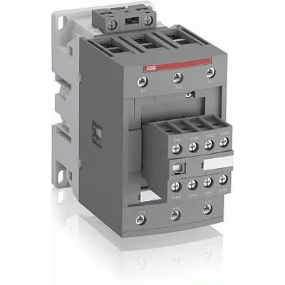
AF96-30-22-12 Block Contactor by ABB is designed to start and stop motors in industrial automation. In unstable networks, control voltage variations can cause coil chatter and unreliable motor control. It meets IEC/EN 60947-4-1 and IEC/EN 60947-1, plus UL 60335-2-40 and CSA certifications for global compliance. This device is optimized for motor protection and control with pre-mounted auxiliary contacts and screw terminals, supporting DIN-rail mounting and simple extension with add-on auxiliary blocks. It’s engineered to handle wide control voltages (48-130 V AC/DC) and built-in surge protection, delivering consistent operation and reduced energy consumption in panels. For engineers, this translates to reliable start-stop performance, lower maintenance, and scalable control in automation projects.
Product Information
Extended Description
1SBL407001R1222 ABB: The AF96-30-22-12 is a 3 pole - 1000 V IEC or 600 UL contactor with pre-mounted auxiliary contacts and screw terminals, controlling motors up to 45 kW / 400 V AC (AC-3) or 60 hp / 480 V UL and switching power circuits up to 130 A (AC-1) or 115 A UL general use. Thanks to the AF technology, the contactor has a wide control voltage range (48-130 V 50/60 Hz and DC), managing large control voltage variations, reducing panel energy consumptions and ensuring distinct operations in unstable networks. Furthermore, surge protection is built-in, offering a compact solution. AF contactors have a block type design, can be easily extended with add-on auxiliary contact blocks and an additional wide range of accessories.
Minimum Order Quantity
1 piece
Customs Tariff Number
85364900
Data Sheet, Technical Information
1SBC100214C0202 - Main catalog Motor protection and control Manual motor starters, contactors and overload relays (PDF) - Edition 2024
Instructions and Manuals
Installation instructions AF(C)40(B)...96(B)-30 Contactors, CA4, CAL4, CAT4, CC4, LDC4 Accessories
Instructions and Manuals (Part 2)
Contactors and Overload relays guide
CAD Dimensional Drawing
Information - 2D and 3D files for CAD systems
Product Net Width
70 mm
Product Net Depth / Length
149 mm
Product Net Height
125.5 mm
Product Net Weight
1.27 kg
Number of Main Contacts NO
3
Number of Main Contacts NC
0
Number of Auxiliary Contacts NO
2
Number of Auxiliary Contacts NC
2
Number of Poles
3P
Standards
IEC/EN 60947-1, IEC/EN 60947-4-1, UL 60335-2-40 LZGH2 A2L, UL 60947-1, UL 60947-4-1, CSA C22.2 No. 60335-2-40 LZGH2 A2L, CSA C22.2 No. 60947-1:22, CSA C22.2 No. 60947-4-1:22
Rated Operational Voltage
Auxiliary Circuit 690 V | Main Circuit 1000 V
Rated Frequency (f)
Auxiliary Circuit 50 / 60 Hz | Control Circuit 50 / 60 Hz | Main Circuit 50 / 60 Hz
Conventional Free-air Thermal Current (Ith)
acc. to IEC 60947-4-1, Open Contactors Θ = 40 °C 130 A | acc. to IEC 60947-5-1, Θ = 40 °C 16 A
Rated Operational Current AC-1 (Ie)
(690 V) 40 °C 130 A | (690 V) 60 °C 105 A | (690 V) 70 °C 90 A
Rated Operational Current AC-3 (Ie)
(415 V) 60 °C 96 A | (440 V) 60 °C 96 A | (500 V) 60 °C 80 A | (690 V) 60 °C 57 A | (1000 V) 60 °C 30 A | (380 / 400 V) 60 °C 105 A | (220 / 230 / 240 V) 60 °C 105 A
Rated Operational Current AC-3e (Ie)
(415 V) 60 °C 96 A | (440 V) 60 °C 96 A | (500 V) 60 °C 80 A | (690 V) 60 °C 57 A | (380 / 400 V) 60 °C 105 A | (220 / 230 / 240 V) 60 °C 105 A
Rated Operational Current AC-15 (Ie)
(500 V) 2 A | (690 V) 2 A | (24 / 127 V) 6 A | (220 / 240 V) 4 A | (400 / 440 V) 3 A
Rated Operational Current DC-1 (Ie)
(110 V) 2 Poles in Series, 40 °C 130 A | (110 V) 2 Poles in Series, 60 °C 105 A | (110 V) 2 Poles in Series, 70 °C 90 A | (110 V) 3 Poles in Series, 40 °C 130 A | (110 V) 3 Poles in Series, 60 °C 105 A | (110 V) 3 Poles in Series, 70 °C 90 A | (220 V) 3 Poles in Series, 40 °C 125 A | (220 V) 3 Poles in Series, 60 °C 105 A | (220 V) 3 Poles in Series, 70 °C 90 A | (72 V) 1-Pole, 40 °C 130 A | (72 V) 1-Pole, 60 °C 105 A | (72 V) 1-Pole, 70 °C 90 A | (72 V) 2 Poles in Series, 40 °C 130 A | (72 V) 2 Poles in Series, 60 °C 105 A | (72 V) 2 Poles in Series, 70 °C 90 A | (72 V) 3 Poles in Series, 40 °C 130 A | (72 V) 3 Poles in Series, 60 °C 105 A | (72 V) 3 Poles in Series, 70 °C 90 A
Rated Operational Current DC-3 (Ie)
(110 V) 2 Poles in Series, 40 °C 130 A | (110 V) 2 Poles in Series, 60 °C 105 A | (110 V) 2 Poles in Series, 70 °C 90 A | (110 V) 3 Poles in Series, 40 °C 130 A | (110 V) 3 Poles in Series, 60 °C 105 A | (110 V) 3 Poles in Series, 70 °C 90 A | (220 V) 3 Poles in Series, 40 °C 130 A | (220 V) 3 Poles in Series, 60 °C 105 A | (220 V) 3 Poles in Series, 70 °C 90 A | (72 V) 1-Pole, 40 °C 130 A | (72 V) 1-Pole, 60 °C 105 A | (72 V) 1-Pole, 70 °C 90 A | (72 V) 2 Poles in Series, 40 °C 130 A | (72 V) 2 Poles in Series, 60 °C 105 A | (72 V) 2 Poles in Series, 70 °C 90 A | (72 V) 3 Poles in Series, 40 °C 130 A | (72 V) 3 Poles in Series, 60 °C 105 A | (72 V) 3 Poles in Series, 70 °C 90 A
Rated Operational Current DC-5 (Ie)
(110 V) 2 Poles in Series, 40 °C 130 A | (110 V) 2 Poles in Series, 60 °C 105 A | (110 V) 2 Poles in Series, 70 °C 90 A | (110 V) 3 Poles in Series, 40 °C 130 A | (110 V) 3 Poles in Series, 60 °C 105 A | (110 V) 3 Poles in Series, 70 °C 90 A | (220 V) 3 Poles in Series, 40 °C 130 A | (220 V) 3 Poles in Series, 60 °C 105 A | (220 V) 3 Poles in Series, 70 °C 90 A | (72 V) 1-Pole, 40 °C 130 A | (72 V) 1-Pole, 60 °C 105 A | (72 V) 1-Pole, 70 °C 90 A | (72 V) 2 Poles in Series, 40 °C 130 A | (72 V) 2 Poles in Series, 60 °C 105 A | (72 V) 2 Poles in Series, 70 °C 90 A | (72 V) 3 Poles in Series, 40 °C 130 A | (72 V) 3 Poles in Series, 60 °C 105 A | (72 V) 3 Poles in Series, 70 °C 90 A
Rated Operational Current DC-13 (Ie)
(24 V) 6 A / 144 W | (48 V) 2.8 A / 134 W | (72 V) 1 A / 72 W | (110 V) 1.1 A / 121 W | (125 V) 0.55 A / 69 W | (220 V) 0.27 A / 60 W | (250 V) 0.27 A / 68 W | (400 V) 0.15 A / 60 W | (500 V) 0.13 A / 65 W | (600 V) 0.1 A / 60 W
Rated Operational Power AC-3 (Pe)
(415 V) 55 kW | (440 V) 55 kW | (500 V) 55 kW | (690 V) 55 kW | (1000 V) 40 kW | (380 / 400 V) 45 kW | (380 / 400 V) 55 kW | (220 / 230 / 240 V) 25 kW | (220 / 230 / 240 V) 30 kW
Rated Operational Power AC-3e (Pe)
(415 V) 55 kW | (440 V) 55 kW | (500 V) 55 kW | (690 V) 55 kW | (380 / 400 V) 45 kW | (380 / 400 V) 55 kW | (220 / 230 / 240 V) 25 kW | (220 / 230 / 240 V) 30 kW
Rated Short-time Withstand Current Low Voltage (Icw)
at 40 °C Ambient Temp, in Free Air, from a Cold State 10 s 840 A | at 40 °C Ambient Temp, in Free Air, from a Cold State 15 min 140 A | at 40 °C Ambient Temp, in Free Air, from a Cold State 1 min 300 A | at 40 °C Ambient Temp, in Free Air, from a Cold State 1 s 1200 A | at 40 °C Ambient Temp, in Free Air, from a Cold State 30 s 450 A | for 0.1 s 140 A | for 1 s 100 A
Maximum Breaking Capacity
cos phi=0.45 (cos phi=0.35 for Ie > 100 A) at 440 V 1150 A | cos phi=0.45 (cos phi=0.35 for Ie > 100 A) at 690 V 750 A
Rated Insulation Voltage (Ui)
acc. to IEC 60947-4-1 1000 V | acc. to IEC 60947-5-1 690 V | acc. to UL/CSA 600 V
Rated Impulse Withstand Voltage (Uimp)
8 kV
Maximum Electrical Switching Frequency
(AC-1) 600 cycles per hour | (AC-15) 1200 cycles per hour | (AC-2 / AC-4) 150 cycles per hour | (AC-3) 1200 cycles per hour | (DC-13) 900 cycles per hour
Maximum Mechanical Switching Frequency
3600 cycles per hour
Rated Control Circuit Voltage (Uc)
50 Hz 48 ... 130 V | 60 Hz 48 ... 130 V | DC Operation 48 ... 130 V
Power Loss
at 6 A per Pole 0.1 W | at Rated Operating Conditions AC-1 per Pole 8.2 W | at Rated Operating Conditions AC-3 per Pole 4.5 W
Operate Time
Between Coil De-energization and NC Contact Closing 19 ... 105 ms | Between Coil De-energization and NO Contact Opening 17 ... 100 ms | Between Coil Energization and NC Contact Opening 38 ... 95 ms | Between Coil Energization and NO Contact Closing 42 ... 100 ms
Mounting on DIN Rail
TH35-15 (35 x 15 mm Mounting Rail) acc. to IEC 60715
Mounting by Screws (not supplied)
2 x M4 or 2 x M6 screws placed diagonally
Connecting Capacity Main Circuit
Flexible with Ferrule 1/2x 6 ... 50 mm² | Flexible with Insulated Ferrule 1/2x 6 ... 50 mm² | Rigid Stranded 1x 6 ... 70 mm² | Rigid Stranded 2x 6 ... 50 mm²
Connecting Capacity Auxiliary Circuit
Flexible with Ferrule 1/2x 0.75 ... 2.5 mm² | Flexible with Insulated Ferrule 2x 0.75 ... 1.5 mm² | Flexible with Insulated Ferrule 1x 0.75 ... 2.5 mm² | Rigid 1/2x 1 ... 2.5 mm²
Connecting Capacity Control Circuit
Flexible with Ferrule 1/2x 0.75 ... 2.5 mm² | Flexible with Insulated Ferrule 1x 0.75 ... 2.5 mm² | Flexible with Insulated Ferrule 2x 0.75 ... 1.5 mm² | Rigid 1/2x 1 ... 2.5 mm²
Wire Stripping Length
Auxiliary Circuit 10 mm | Control Circuit 10 mm | Main Circuit 17 mm
Degree of Protection
acc. to IEC 60529, IEC 60947-1, EN 60529 Auxiliary Terminals IP20 | acc. to IEC 60529, IEC 60947-1, EN 60529 Coil Terminals IP20 | acc. to IEC 60529, IEC 60947-1, EN 60529 Main Terminals IP10
Tightening Torque
Auxiliary Circuit 1.2 N·m | Control Circuit 1.2 N·m | Main Circuit 6 N·m
Terminal Type
Screw Terminals
Product Name
Block Contactor
Maximum Operating Voltage UL/CSA
Main Circuit 600 V
General Use Rating UL/CSA
(600 V AC) 115 A
Horsepower Rating UL/CSA
(120 V AC) Single Phase 7-1/2 hp | (200 ... 208 V AC) Three Phase 30 hp | (220 ... 240 V AC) Three Phase 40 hp | (240 V AC) Single Phase 20 hp | (440 ... 480 V AC) Three Phase 75 hp | (550 ... 600 V AC) Three Phase 75 hp
Connecting Capacity Main Circuit UL/CSA
Rigid Stranded 1/2x 6-1 AWG
Tightening Torque UL/CSA
Auxiliary Circuit 11 in·lb | Control Circuit 11 in·lb | Main Circuit 53 in·lb
Full Load Amps Motor Use
(120 V AC) Single Phase 80 A | (200 ... 208 V AC) Three Phase 92 A | (220 ... 240 V AC) Three Phase 80 A | (240 V AC) Single Phase 88 A | (440 ... 480 V AC) Three Phase 77 A | (550 ... 600 V AC) Three Phase 77 A
Ambient Air Temperature
Close to Contactor Fitted with Thermal O/L Relay -40 ... 70 °C | Close to Contactor without Thermal O/L Relay -40 ... 70 °C | Close to Contactor for Storage -60 ... +80 °C
Climatic Withstand
Category B according to IEC 60947-1 Annex Q
Maximum Operating Altitude Permissible
Without Derating 3000 m
Resistance to Shock acc. to IEC 60068-2-27
Closed, Shock Direction: A 25 g | Closed, Shock Direction: B1 25 g | Closed, Shock Direction: B2 15 g | Closed, Shock Direction: C1 25 g | Closed, Shock Direction: C2 25 g | Open, Shock Direction: B1 5 g
Resistance to Vibrations
3g Closed Position & 3g Open Position 5 ... 300 Hz
Pollution Degree
3
Conflict Minerals Reporting Template (CMRT)
CMRT - Conflict Minerals Reporting Template
REACH Declaration
REACH - Letter of Confirmation for block contactors, contactor relays, installation contactors, mini contactors, mini contactor relays, thermal overload relays, electronic overload relays and related accessories
RoHS Information
RoHS II declaration for block contactors, installation contactors, mini contactors, mini contactor relays, thermal overload relays, electronic overload relays and related accessories
RoHS Status
Following EU Directive 2011/65/EU and Amendment 2015/863 July 22, 2019
Toxic Substances Control Act - TSCA
Toxic Substances Control Act (TSCA) declaration for Contactors
WEEE B2C / B2B
Business To Business
WEEE Category
5. Small Equipment (No External Dimension More Than 50 cm)
ABB EcoSolutions
Yes
End Of Life Disassembling Instructions
End of life instruction AF(S)40/52/65/80/96(B)(RT) Contactors
Environmental Product Declaration - EPD
Environmental Product Declaration AF(S)80(B), AF(S)96(B) (FR)
Sustainable Material Content in Packaging (wt. %)
FSC Recycled Paper - 94.6 %
Sustainable Material Content in Product (wt. %)
Recycled Metal - 28.2 %
A2L Certificate – UL
UL-US Certificate of Compliance AF40 ... AF96 3-pole contactors - UL 60335-2-40 Household and Similar Electrical Appliances - Safety - Part 2-40: Particular Requirements for Electrical Heat Pumps, Air-Conditioners and Dehumidifiers | UL-CA Certificate of Compliance AF40 ... AF96 3-pole contactors - CSA C22.2 No. 60335-2-40 Household and Similar Electrical Appliances - Safety - Part 2-40: Particular Requirements for Electrical Heat Pumps, Air-Conditioners and Dehumidifiers
ABS Certificate
ABS Certificate, AF(S)09 to AF(S)96 contactors, NF contactor relays and CA4, CC4, CAL4, CAT4 auxiliary contact blocks, TEF4 electronic timers
BV Certificate
BV_2634H36994B1
CB Certificate
CB Certificate AF(S)80(B), AF(S)96(B) 3 and 4-pole contactors
CCC Certificate
CQC Certificate, AC Contactor, AF(S)*80-30-**-**, AF80-40-**-**, AF80-22-**-**, AF(S)96-30-**-**, Made in France
Declaration of Conformity - CCC
CCC Declaration of Conformity, AC Contactor, AF*80-30-**-**, AF80-40-**-**, AF80-22-**-**, AF*96-30-**-**, Made in France
Declaration of Conformity - CE
EU Declaration of Conformity AF09... AF96-30-.., AF09...38(Z)-30..K 3-pole Contactors
Declaration of Conformity - UKCA
UK Declaration of Conformity AF09... AF96-30-.., AF09...38(Z)-30..K 3-pole Contactors
DNV Certificate
DNV Certificate AF(S)09...96 3-pole & AF09...80 4-pole contactors with screw, spring, push-in terminals
KC Certificate
KC Certificate AF80, AF96 3-pole Contactors
LR Certificate
LRS Certificate AF(S)09..(K) ... AF96 3 and 4-pole contactors and CA(L)4..(K), CAT4, CC4 auxiliary contact blocks
RINA Certificate
Rina Certificate for AF09...AF96 contactors, NF contactor relays and accessories, screw and spring terminals
RMRS Certificate
RMRS Certificate AF(S)09(S)...AF(S)38 3-pole and 4-pole, AF(S)40..96 3-pole contactors with screw, push-in and spring terminals
UL Certificate
UL-US-L312527-1141-10303102-9 | UL-CA-L312527-4141-10303102-9
UL Listing Card
UL_E312527
Package Level 1 Units
box 1 piece
Package Level 1 Width
180 mm
Package Level 1 Depth / Length
150 mm
Package Level 1 Height
102 mm
Package Level 1 Gross Weight
1.41 kg
Package Level 1 EAN
3471523133426
Package Level 2 Units
box 6 piece
Package Level 2 Width
250 mm
Package Level 2 Depth / Length
300 mm
Package Level 2 Height
300 mm
Package Level 2 Gross Weight
8.46 kg
Package Level 3 Units
144 piece
Object Classification Code
Q
ETIM 7
EC000066 - Power contactor, AC switching
ETIM 8
EC000066 - Power contactor, AC switching
ETIM 9
EC000066 - Power contactor, AC switching
eClass
V11.0 : 27371003
UNSPSC
39121529
IDEA Granular Category Code (IGCC)
4758 >> Iec Contactors
E-Number (Finland)
3707146
Feature: 3-pole configuration with 3 main NO contacts and 2 NO auxiliary contacts enables compact, high-current motor switching. Business Impact: Reduces component count while delivering robust control of motors up to 45 kW at 400 V AC (AC-3), lowering installation time and total cost of ownership. Application: conveyor systems, pumps, and machine tools where space is at a premium and reliable switching is critical. Feature: Wide control voltage range 48-130 V AC/DC with surge protection. Business Impact: Maintains reliable operation despite voltage variations, improving line voltage tolerance and reducing nuisance tripping. Application: automation panels in facilities with irregular power quality or long cable runs. Feature: Built-in surge protection and compact block design. Business Impact: Protects control circuits, extends device life, and simplifies wiring with fewer external components. Application: compact control cabinets and distributed motor starters. Feature: DIN rail mounting TH35-15 and screw-terminal connections. Business Impact: Easy retrofits and scalable installations in existing panels, enabling rapid deployment and upgrades. Application: industrial automation builds and maintenance projects. Feature: Rated operational currents across multiple voltages (AC-1 up to 130 A, AC-3 up to 96 A, DC-13/ DC-5 variants). Business Impact: Broad applicability for different motor types and load profiles, simplifying part selection and stocking. Application: mixed-voltage control panels and multi-speed drives. Feature: Compliance with IEC/EN and UL/CSA standards. Business Impact: Simplifies regulatory approvals and expedites project commissioning, reducing risk of non-conformance. Application: global deployments in manufacturing and process industries. Feature: ABB EcoSolutions and sustainable packaging. Business Impact: Improves environmental footprint and supports corporate ESG goals while maintaining reliability. Application: projects with sustainability targets and customer compliance requirements.
Get a Quick Quote for a ABB 1SBL407001R1222
Chat with us on WhatsApp - fast responses guaranteed
Need to speak with someone? We'll call you back within 2 hours during business hours
Interested in ABB 1SBL407001R1222?
Enquire Now
FAQs
The AF96-30-22-12 supports DIN rail mounting on TH35-15 (35 x 15 mm) and can be secured with two screws (M4 or M6) placed diagonally for a stable installation. This makes it ideal for compact control panels and retrofit projects where space is limited and speed of installation matters.
The coil accepts 48 to 130 volts across AC or DC operation, covering 50/60 Hz control circuits. This wide tolerance reduces the need for multiple coil variants, simplifies inventory, and provides robust operation in networks with voltage fluctuations common in industrial environments.
Yes. The AF96-30-22-12 is rated for AC-3 operation at various voltages, including up to 690 V, with current ratings up to 96 A for AC-3, depending on the voltage. It also supports AC-1, AC-13, and DC-13 configurations, enabling use in pumps, conveyors, and general motor control starters.
The device complies with IEC/EN 60947-1 and IEC/EN 60947-4-1, and UL 60335-2-40 among others, including CSA references. This broad certification scope supports global deployments and smoother audits for electrical equipment in industrial facilities.
Use the built-in surge protection and compact block design to reduce external snubbers. Favor DIN-rail mounting for modular scalability, wire with appropriate ferrules for main and auxiliary circuits, and leverage pre-mounted auxiliary contacts to minimize wiring. This approach lowers maintenance frequency, reduces downtime, and accelerates project ROI through faster commissioning.