ABB 1SBL407001R1400 Block Contactor - IEC/UL Listed
Part Number: 1SBL407001R1400
Quick Summary
ABB 1SBL407001R1400 block contactor is a robust 3-pole device for motor control in industrial automation. The design addresses voltage fluctuations and panel energy waste that can cause nuisance trips and inconsistent starts. It meets key standards including IEC/EN 60947-4-1, UL 60335-2-40, and CSA approvals, with IP protection considerations for coils and main terminals. This solution also supports AF technology for broad control voltage tolerance, and it pairs well with add-on auxiliary blocks for scalable control architectures, delivering reliable performance in demanding environments while optimizing lifecycle costs.
Product Information
Extended Description
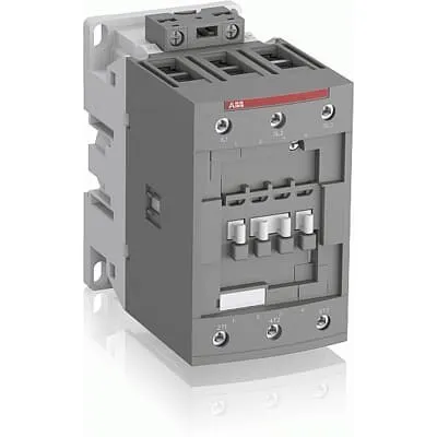
1SBL407001R1400 ABB: The AF96-30-00-14 is a 3 pole - 1000 V IEC or 600 UL contactor with screw terminals, controlling motors up to 45 kW / 400 V AC (AC-3) or 60 hp / 480 V UL and switching power circuits up to 130 A (AC-1) or 115 A UL general use. Thanks to the AF technology, the contactor has a wide control voltage range (250-500 V 50/60 Hz and DC), managing large control voltage variations, reducing panel energy consumptions and ensuring distinct operations in unstable networks. Furthermore, surge protection is built-in, offering a compact solution. AF contactors have a block type design, can be easily extended with add-on auxiliary contact blocks and an additional wide range of accessories.
Minimum Order Quantity
1 piece
Customs Tariff Number
85364900
Data Sheet, Technical Information
1SBC100214C0202 - Main catalog Motor protection and control Manual motor starters, contactors and overload relays (PDF) - Edition 2024
Instructions and Manuals
Installation instructions AF(C)40(B)...96(B)-30 Contactors, CA4, CAL4, CAT4, CC4, LDC4 Accessories
Instructions and Manuals (Part 2)
Contactors and Overload relays guide
CAD Dimensional Drawing
Information - 2D and 3D files for CAD systems
Product Net Width
70 mm
Product Net Depth / Length
116 mm
Product Net Height
125.5 mm
Product Net Weight
1.17 kg
Number of Main Contacts NO
3
Number of Main Contacts NC
0
Number of Auxiliary Contacts NO
0
Number of Auxiliary Contacts NC
0
Number of Poles
3P
Standards
IEC/EN 60947-1, IEC/EN 60947-4-1, UL 60335-2-40 LZGH2 A2L, UL 60947-1, UL 60947-4-1, CSA C22.2 No. 60335-2-40 LZGH2 A2L, CSA C22.2 No. 60947-1:22, CSA C22.2 No. 60947-4-1:22
Rated Operational Voltage
Main Circuit 1000 V
Rated Frequency (f)
Control Circuit 50 / 60 Hz | Main Circuit 50 / 60 Hz
Conventional Free-air Thermal Current (Ith)
acc. to IEC 60947-4-1, Open Contactors Θ = 40 °C 130 A
Rated Operational Current AC-1 (Ie)
(690 V) 40 °C 130 A | (690 V) 60 °C 105 A | (690 V) 70 °C 90 A
Rated Operational Current AC-3 (Ie)
(415 V) 60 °C 96 A | (440 V) 60 °C 96 A | (500 V) 60 °C 80 A | (690 V) 60 °C 57 A | (1000 V) 60 °C 30 A | (380 / 400 V) 60 °C 105 A | (220 / 230 / 240 V) 60 °C 105 A
Rated Operational Current AC-3e (Ie)
(415 V) 60 °C 96 A | (440 V) 60 °C 96 A | (500 V) 60 °C 80 A | (690 V) 60 °C 57 A | (380 / 400 V) 60 °C 105 A | (220 / 230 / 240 V) 60 °C 105 A
Rated Operational Current DC-1 (Ie)
(110 V) 2 Poles in Series, 40 °C 130 A | (110 V) 2 Poles in Series, 60 °C 105 A | (110 V) 2 Poles in Series, 70 °C 90 A | (110 V) 3 Poles in Series, 40 °C 130 A | (110 V) 3 Poles in Series, 60 °C 105 A | (110 V) 3 Poles in Series, 70 °C 90 A | (220 V) 3 Poles in Series, 40 °C 125 A | (220 V) 3 Poles in Series, 60 °C 105 A | (220 V) 3 Poles in Series, 70 °C 90 A | (72 V) 1-Pole, 40 °C 130 A | (72 V) 1-Pole, 60 °C 105 A | (72 V) 1-Pole, 70 °C 90 A | (72 V) 2 Poles in Series, 40 °C 130 A | (72 V) 2 Poles in Series, 60 °C 105 A | (72 V) 2 Poles in Series, 70 °C 90 A | (72 V) 3 Poles in Series, 40 °C 130 A | (72 V) 3 Poles in Series, 60 °C 105 A | (72 V) 3 Poles in Series, 70 °C 90 A
Rated Operational Current DC-3 (Ie)
(110 V) 2 Poles in Series, 40 °C 130 A | (110 V) 2 Poles in Series, 60 °C 105 A | (110 V) 2 Poles in Series, 70 °C 90 A | (110 V) 3 Poles in Series, 40 °C 130 A | (110 V) 3 Poles in Series, 60 °C 105 A | (110 V) 3 Poles in Series, 70 °C 90 A | (220 V) 3 Poles in Series, 40 °C 130 A | (220 V) 3 Poles in Series, 60 °C 105 A | (220 V) 3 Poles in Series, 70 °C 90 A | (72 V) 1-Pole, 40 °C 130 A | (72 V) 1-Pole, 60 °C 105 A | (72 V) 1-Pole, 70 °C 90 A | (72 V) 2 Poles in Series, 40 °C 130 A | (72 V) 2 Poles in Series, 60 °C 105 A | (72 V) 2 Poles in Series, 70 °C 90 A | (72 V) 3 Poles in Series, 40 °C 130 A | (72 V) 3 Poles in Series, 60 °C 105 A | (72 V) 3 Poles in Series, 70 °C 90 A
Rated Operational Current DC-5 (Ie)
(110 V) 2 Poles in Series, 40 °C 130 A | (110 V) 2 Poles in Series, 60 °C 105 A | (110 V) 2 Poles in Series, 70 °C 90 A | (110 V) 3 Poles in Series, 40 °C 130 A | (110 V) 3 Poles in Series, 60 °C 105 A | (110 V) 3 Poles in Series, 70 °C 90 A | (220 V) 3 Poles in Series, 40 °C 130 A | (220 V) 3 Poles in Series, 60 °C 105 A | (220 V) 3 Poles in Series, 70 °C 90 A | (72 V) 1-Pole, 40 °C 130 A | (72 V) 1-Pole, 60 °C 105 A | (72 V) 1-Pole, 70 °C 90 A | (72 V) 2 Poles in Series, 40 °C 130 A | (72 V) 2 Poles in Series, 60 °C 105 A | (72 V) 2 Poles in Series, 70 °C 90 A | (72 V) 3 Poles in Series, 40 °C 130 A | (72 V) 3 Poles in Series, 60 °C 105 A | (72 V) 3 Poles in Series, 70 °C 90 A
Rated Operational Power AC-3 (Pe)
(415 V) 55 kW | (440 V) 55 kW | (500 V) 55 kW | (690 V) 55 kW | (1000 V) 40 kW | (380 / 400 V) 45 kW | (380 / 400 V) 55 kW | (220 / 230 / 240 V) 25 kW | (220 / 230 / 240 V) 30 kW
Rated Operational Power AC-3e (Pe)
(415 V) 55 kW | (440 V) 55 kW | (500 V) 55 kW | (690 V) 55 kW | (380 / 400 V) 45 kW | (380 / 400 V) 55 kW | (220 / 230 / 240 V) 25 kW | (220 / 230 / 240 V) 30 kW
Rated Short-time Withstand Current Low Voltage (Icw)
at 40 °C Ambient Temp, in Free Air, from a Cold State 10 s 840 A | at 40 °C Ambient Temp, in Free Air, from a Cold State 15 min 140 A | at 40 °C Ambient Temp, in Free Air, from a Cold State 1 min 300 A | at 40 °C Ambient Temp, in Free Air, from a Cold State 1 s 1200 A | at 40 °C Ambient Temp, in Free Air, from a Cold State 30 s 450 A
Maximum Breaking Capacity
cos phi=0.45 (cos phi=0.35 for Ie > 100 A) at 440 V 1150 A | cos phi=0.45 (cos phi=0.35 for Ie > 100 A) at 690 V 750 A
Rated Insulation Voltage (Ui)
acc. to IEC 60947-4-1 1000 V | acc. to UL/CSA 600 V
Rated Impulse Withstand Voltage (Uimp)
8 kV
Maximum Electrical Switching Frequency
(AC-1) 600 cycles per hour | (AC-2 / AC-4) 150 cycles per hour | (AC-3) 1200 cycles per hour
Maximum Mechanical Switching Frequency
3600 cycles per hour
Rated Control Circuit Voltage (Uc)
50 Hz 250 ... 500 V | 60 Hz 250 ... 500 V | DC Operation 250 ... 500 V
Coil Consumption
Average Holding Value 50 / 60 Hz 4 V·A | Average Holding Value 50 Hz 4 V·A | Average Holding Value 60 Hz 4 V·A | Average Holding Value DC 2 W | Average Holding Value, from Warm State 2 W
Power Loss
at Rated Operating Conditions AC-1 per Pole 8.2 W | at Rated Operating Conditions AC-3 per Pole 4.5 W
Operate Time
Between Coil De-energization and NC Contact Closing 19 ... 105 ms | Between Coil De-energization and NO Contact Opening 17 ... 100 ms | Between Coil Energization and NC Contact Opening 38 ... 95 ms | Between Coil Energization and NO Contact Closing 42 ... 100 ms
Mounting on DIN Rail
TH35-15 (35 x 15 mm Mounting Rail) acc. to IEC 60715
Mounting by Screws (not supplied)
2 x M4 or 2 x M6 screws placed diagonally
Connecting Capacity Main Circuit
Flexible with Ferrule 1/2x 6 ... 50 mm² | Flexible with Insulated Ferrule 1/2x 6 ... 50 mm² | Rigid Stranded 1x 6 ... 70 mm² | Rigid Stranded 2x 6 ... 50 mm²
Connecting Capacity Control Circuit
Flexible with Ferrule 1/2x 0.75 ... 2.5 mm² | Flexible with Insulated Ferrule 1x 0.75 ... 2.5 mm² | Flexible with Insulated Ferrule 2x 0.75 ... 1.5 mm² | Rigid Solid 1/2x 1 ... 2.5 mm² | Rigid Stranded 1/2x 1 ... 2.5 mm²
Wire Stripping Length
Control Circuit 10 mm | Main Circuit 17 mm
Degree of Protection
acc. to IEC 60529, IEC 60947-1, EN 60529 Coil Terminals IP20 | acc. to IEC 60529, IEC 60947-1, EN 60529 Main Terminals IP10
Recommended Screw Driver
Pozidriv PZ
Tightening Torque
Control Circuit 1.2 N·m | Main Circuit 6 N·m
Terminal Type
Screw Terminals
Product Name
Block Contactor
Maximum Operating Voltage UL/CSA
Main Circuit 600 V
General Use Rating UL/CSA
(600 V AC) 115 A
Horsepower Rating UL/CSA
(120 V AC) Single Phase 7-1/2 hp | (200 ... 208 V AC) Three Phase 30 hp | (220 ... 240 V AC) Three Phase 40 hp | (240 V AC) Single Phase 20 hp | (440 ... 480 V AC) Three Phase 75 hp | (550 ... 600 V AC) Three Phase 75 hp
Connecting Capacity Main Circuit UL/CSA
Rigid Stranded 1/2x 6-1 AWG
Connecting Capacity Control Circuit UL/CSA
Rigid Solid 1/2x 18-14 AWG | Rigid Stranded 1/2x 18-14 AWG
Tightening Torque UL/CSA
Control Circuit 11 in·lb | Main Circuit 53 in·lb
Full Load Amps Motor Use
(120 V AC) Single Phase 80 A | (200 ... 208 V AC) Three Phase 92 A | (220 ... 240 V AC) Three Phase 80 A | (240 V AC) Single Phase 88 A | (440 ... 480 V AC) Three Phase 77 A | (550 ... 600 V AC) Three Phase 77 A
Ambient Air Temperature
Close to Contactor Fitted with Thermal O/L Relay -40 ... 70 °C | Close to Contactor without Thermal O/L Relay -40 ... 70 °C | Close to Contactor for Storage -60 ... +80 °C
Climatic Withstand
Category B according to IEC 60947-1 Annex Q
Maximum Operating Altitude Permissible
Without Derating 3000 m
Resistance to Shock acc. to IEC 60068-2-27
Closed, Shock Direction: A 25 g | Closed, Shock Direction: B1 25 g | Closed, Shock Direction: B2 15 g | Closed, Shock Direction: C1 25 g | Closed, Shock Direction: C2 25 g | Open, Shock Direction: B1 5 g
Resistance to Vibrations
3g Closed Position & 3g Open Position 5 ... 300 Hz
Pollution Degree
3
Conflict Minerals Reporting Template (CMRT)
CMRT - Conflict Minerals Reporting Template
REACH Declaration
REACH - Letter of Confirmation for block contactors, contactor relays, installation contactors, mini contactors, mini contactor relays, thermal overload relays, electronic overload relays and related accessories
RoHS Information
RoHS II declaration for block contactors, installation contactors, mini contactors, mini contactor relays, thermal overload relays, electronic overload relays and related accessories
RoHS Status
Following EU Directive 2011/65/EU and Amendment 2015/863 July 22, 2019
SCIP
c4877b1a-61b0-4035-af81-19b0d032e421 France (FR)
Simplified SCIP
5d7edeba-2b1c-46ec-bfa9-27d25c2c8e7f Poland (PL) | 5f74e085-165b-42cd-ab44-8ea845d5c2f7 Netherlands (NL) | 8db503e9-559a-4265-892d-054efcdedec1 Sweden (SE) | 515736cf-d872-4e7d-89a3-83be6815bdf2 Poland (PL) | 4ecd0f72-605e-4fd0-b93c-a8579826a6d1 France (FR) | d3689385-4747-4921-8eba-5595c55381b0 Sweden (SE) | ccbc359e-c1d3-407e-bbe7-14f84cfa6fb2 Germany (DE) | 564b7429-d6d1-48ec-9572-b7fdf5d73ad6 Germany (DE) | 73d4dfcd-c46c-4a00-9e2f-25b3c8e1a51b Hungary (HU) | d84df9fc-68f4-4b35-bd3f-45faa6f3696b Spain (ES) | 0b11bef2-0985-4731-ad77-c7a59564e4e3 Belgium (BE) | e7066cfa-017c-4709-bb73-edd2f254eca3 Czech Republic (CZ) | 33bf5972-7c54-4da5-83cb-b137cb8796b8 Croatia (HR) | 02b5e63a-e63a-429e-978a-bfce7b95ff75 Germany (DE) | 3d403a80-6227-4398-b452-9b9ddc58a466 Denmark (DK) | b798b11c-6af6-4bdd-bb6b-281c5b7f7f43 Germany (DE) | 1f7b6afe-a85e-411e-8fb5-78b356681643 Italy (IT) | 09b352a8-9482-476c-8ff6-3bf9358b7512 Germany (DE) | c79e3fcd-ca9a-4387-9cd9-738874827ca1 Norway (NO) | 2fd26b13-a070-4d48-b404-52e6cf2c2971 Finland (FI) | e070fbbe-084e-4d98-8ba7-363823bd1f08 Belgium (BE) | 031b0076-64ef-49ad-beca-3a4b27bfb9a2 Bulgaria (BG) | 1fc6aa7a-fea6-422a-99de-cd6ad162d34c Poland (PL) | ef0a90d2-ea3f-4a65-813e-6b91027d60ef Hungary (HU) | e3899935-fc17-4ff1-9d6a-d98d21124e40 Estonia (EE) | fe142014-b10c-4c8a-a9e4-fc744649db22 Greece (GR) | 7b855ad7-2124-4f79-bcec-12acf889ffef Portugal (PT)
Toxic Substances Control Act - TSCA
Toxic Substances Control Act (TSCA) declaration for Contactors
WEEE B2C / B2B
Business To Business
WEEE Category
5. Small Equipment (No External Dimension More Than 50 cm)
ABB EcoSolutions
Yes
End Of Life Disassembling Instructions
End of life instruction AF(S)40/52/65/80/96(B)(RT) Contactors
Environmental Product Declaration - EPD
Environmental Product Declaration AF80, AF96 (CN) Contactors | Environmental Product Declaration AF(S)80(B), AF(S)96(B) (FR)
Sustainable Material Content in Packaging (wt. %)
FSC Recycled Paper - 94.6 %
Sustainable Material Content in Product (wt. %)
Recycled Metal - 28.2 %
A2L Certificate – UL
UL-US Certificate of Compliance AF40 ... AF96 3-pole contactors - UL 60335-2-40 Household and Similar Electrical Appliances - Safety - Part 2-40: Particular Requirements for Electrical Heat Pumps, Air-Conditioners and Dehumidifiers | UL-CA Certificate of Compliance AF40 ... AF96 3-pole contactors - CSA C22.2 No. 60335-2-40 Household and Similar Electrical Appliances - Safety - Part 2-40: Particular Requirements for Electrical Heat Pumps, Air-Conditioners and Dehumidifiers
ABS Certificate
ABS Certificate, AF(S)09 to AF(S)96 contactors, NF contactor relays and CA4, CC4, CAL4, CAT4 auxiliary contact blocks, TEF4 electronic timers
BV Certificate
BV_2634H36994B1
CB Certificate
CB Certificate AF(S)80(B), AF(S)96(B) 3 and 4-pole contactors
CCC Certificate
CQC Certificate, AC Contactor, AF(S)*80-30-**-**, AF80-40-**-**, AF80-22-**-**, AF(S)96-30-**-**, Made in France
Declaration of Conformity - CCC
CCC Declaration of Conformity, AC Contactor, AF*80-30-**-**, AF80-40-**-**, AF80-22-**-**, AF*96-30-**-**, Made in France
Declaration of Conformity - CE
EU Declaration of Conformity AF09... AF96-30-.., AF09...38(Z)-30..K 3-pole Contactors
Declaration of Conformity - UKCA
UK Declaration of Conformity AF09... AF96-30-.., AF09...38(Z)-30..K 3-pole Contactors
DNV Certificate
DNV Certificate AF(S)09...96 3-pole & AF09...80 4-pole contactors with screw, spring, push-in terminals
KC Certificate
KC Certificate AF80, AF96 3-pole Contactors
LR Certificate
LRS Certificate AF(S)09..(K) ... AF96 3 and 4-pole contactors and CA(L)4..(K), CAT4, CC4 auxiliary contact blocks
RINA Certificate
Rina Certificate for AF09...AF96 contactors, NF contactor relays and accessories, screw and spring terminals
RMRS Certificate
RMRS Certificate AF(S)09(S)...AF(S)38 3-pole and 4-pole, AF(S)40..96 3-pole contactors with screw, push-in and spring terminals
UL Certificate
UL-US-L312527-1141-10303102-9 | UL-CA-L312527-4141-10303102-9
UL Listing Card
UL_E312527
Package Level 1 Units
box 1 piece
Package Level 1 Width
150 mm
Package Level 1 Depth / Length
150 mm
Package Level 1 Height
103 mm
Package Level 1 Gross Weight
1.29 kg
Package Level 1 EAN
3471523133242
Package Level 2 Units
box 8 piece
Package Level 2 Width
250 mm
Package Level 2 Depth / Length
300 mm
Package Level 2 Height
300 mm
Package Level 2 Gross Weight
10.32 kg
Package Level 3 Units
192 piece
Object Classification Code
Q
ETIM 7
EC000066 - Power contactor, AC switching
ETIM 8
EC000066 - Power contactor, AC switching
ETIM 9
EC000066 - Power contactor, AC switching
eClass
V11.0 : 27371003
UNSPSC
39121529
IDEA Granular Category Code (IGCC)
4758 >> Iec Contactors
E-Number (Finland)
3707138
E-Number (Sweden)
3210058
Feature → Business Impact → Application: The AF technology driving this 3-pole block contactor delivers a wide control voltage range of 250–500 V AC (and DC), reducing control circuit variability and enabling stable operation in networks with voltage fluctuations. This translates to fewer panel trips and improved machine uptime in manufacturing lines. Application: motor control panels requiring dependable switching across varying mains conditions. Feature → Business Impact → Application: With a main circuit rated up to 1000 V and AC-3 current up to 105 A (at 60°C) and 96 A (AC-3e for common voltages), this device supports high-load conveyors, pumps, and machine tools with predictable performance and energy efficiency. Application: industrial drives and machine automation where reliability under diverse voltages matters. Feature → Business Impact → Application: Built-in surge protection and a compact block design enable easy integration in control cabinets, with the ability to extend functionality via auxiliary contact blocks. Application: modular control systems that require scalable control logic and quick field wiring; ideal for retrofit projects. Feature → Business Impact → Application: Screw terminals and broad wire-range compatibility (main circuit 1/2x 6 … 50 mm²; control circuit 0.75 … 2.5 mm²) reduce installation time and wiring errors, cutting commissioning costs. Application: new installations and panel upgrades where fast, reliable wiring is essential. Feature → Business Impact → Application: DIN rail mounting (TH35-15) and support for a range of standards (IEC/EN 60947-1, IEC/EN 60947-4-1, UL 60335-2-40) provide industry-validated safety and interoperability. Application: standardized panel design in automotive, packaging, and material handling lines. Feature → Business Impact → Application: The contactor’s compact form factor and high short-time withstand currents improve panel density and protection coordination, enabling safer shutdowns and easier compliance demonstrations. Application: safety-critical machinery where space, protection coordination, and regulatory adherence are priorities.
Get a Quick Quote for a ABB 1SBL407001R1400
Chat with us on WhatsApp - fast responses guaranteed
Need to speak with someone? We'll call you back within 2 hours during business hours
Interested in ABB 1SBL407001R1400?
Enquire Now
FAQs
The product supports DIN rail mounting on TH35-15 (35 x 15 mm). If mounting on a panel, screws can be used (2 x M4 or 2 x M6 placed diagonally). For compact, tool-free installation in control cabinets, DIN rail mounting is the preferred method unless space or panel design dictates screw mounting.
Rated Operational Current AC-3e is 96 A at 415–440 V and 105 A at 380/400 V; AC-3 is 96 A at 415/440/500 V and up to 57 A at 690 V; AC-1 current ranges up to 130 A for 110 V configurations. Main circuit current varies by voltage, with 130 A e at 690 V across AC-1 open states.
Yes. The 1SBL407001R1400 complies with IEC/EN 60947-4-1, UL 60335-2-40, and CSA counterparts. It also carries CE and UKCA declarations where applicable, ensuring suitability for global motor-control panels in industrial environments.
Main circuit connections accept flexible with ferrule 1/2 x 6 … 50 mm², flexible insulated ferrule 1/2 x 6 … 50 mm², rigid stranded 1 x 6 … 70 mm², and rigid stranded 2 x 6 … 50 mm². Control circuit accepts flex ferrule 1/2 x 0.75 … 2.5 mm², flexible insulated ferrule 2 x 0.75 … 1.5 mm², rigid solid 1/2 x 1 … 2.5 mm², or rigid stranded 1/2 x 1 … 2.5 mm².
Leverage add-on auxiliary contact blocks and compatible accessories to tailor control circuits. Follow end-of-life instructions AF(S)40/52/65/80/96(B)(RT) and reference installation manuals for AF(C)40/96(B) models. Regular inspection of terminations and torque checks (Main circuit 6 N·m; Control circuit 1.2 N·m) helps sustain reliability in harsh environments.