ABB 1SBX211321R1122 Reversing Contactor - UL/CSA
Part Number: 1SBX211321R1122
Quick Summary
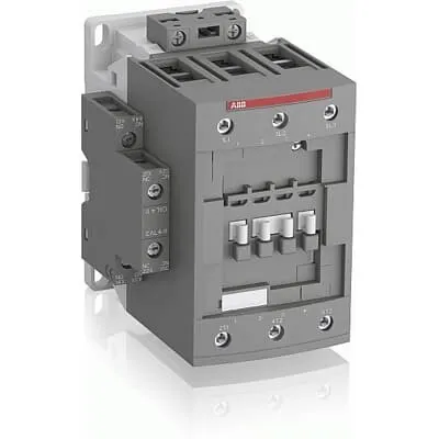
ABB 1SBX211321R1122 Reversing Contactor is a 3-pole control device used to reverse motor direction in industrial equipment. It helps eliminate hazardous manual switching and reduces wear on mechanical interlocks, boosting uptime in demanding production lines. This unit complies with IEC/EN 60947-1 and 60947-4-1, UL/CSA safety listings, and supports DIN rail mounting for quick installation. For engineers, the coil voltage range of 24–60 V accommodates both AC and DC control systems, enabling flexible integration with existing automation architectures. The combination of reliable protection, compact footprint, and straightforward wiring translates to lower maintenance costs and faster project delivery in industrial automation environments.
Product Information
Extended Description
1SBX211321R1122 ABB: AF80R-30-22-11 24-60V50/60HZ 20-60VDC Reversing Contactor
Minimum Order Quantity
1 piece
Customs Tariff Number
85364900
Instructions and Manuals (Part 2)
Contactors and Overload relays guide
CAD Dimensional Drawing
Information - 2D and 3D files for CAD systems
Product Net Width
140 mm
Product Net Depth / Length
149 mm
Product Net Height
151 mm
Product Net Weight
2.746 kg
Number of Main Contacts NO
3
Number of Main Contacts NC
0
Number of Auxiliary Contacts NO
2
Number of Auxiliary Contacts NC
2
Number of Poles
3P
Standards
IEC/EN 60947-1, IEC/EN 60947-4-1, UL 60335-2-40 LZGH2 A2L, UL 60947-1, UL 60947-4-1, CSA C22.2 No. 60335-2-40 LZGH2 A2L, CSA C22.2 No. 60947-1:22, CSA C22.2 No. 60947-4-1:22
Rated Operational Voltage
Auxiliary Circuit 690 V | Main Circuit 1000 V
Rated Frequency (f)
Auxiliary Circuit 50 / 60 Hz | Control Circuit 50 / 60 Hz | Main Circuit 50 / 60 Hz
Rated Operational Current AC-1 (Ie)
(1000 V) 60 °C 100 A | (690 V) 40 °C 125 A | (690 V) 70 °C 85 A
Rated Operational Current AC-3 (Ie)
(415 V) 60 °C 80 A | (440 V) 60 °C 80 A | (500 V) 60 °C 65 A | (690 V) 60 °C 49 A | (1000 V) 60 °C 25 A | (380 / 400 V) 60 °C 80 A | (220 / 230 / 240 V) 60 °C 80 A
Rated Operational Current AC-3e (Ie)
(415 V) 60 °C 80 A | (440 V) 60 °C 80 A | (500 V) 60 °C 65 A | (690 V) 60 °C 49 A | (380 / 400 V) 60 °C 80 A | (220 / 230 / 240 V) 60 °C 80 A
Rated Operational Current AC-15 (Ie)
(500 V) 2 A | (690 V) 2 A | (24 / 127 V) 6 A | (220 / 240 V) 4 A | (400 / 440 V) 3 A
Rated Operational Current DC-13 (Ie)
(24 V) 6 A / 144 W | (48 V) 2.8 A / 134 W | (72 V) 1 A / 72 W | (110 V) 0.55 A / 60 W | (125 V) 0.55 A / 69 W | (220 V) 0.27 A / 60 W | (250 V) 0.27 A / 68 W | (400 V) 0.15 A / 60 W | (500 V) 0.13 A / 65 W | (600 V) 0.1 A / 60 W
Rated Operational Power AC-3 (Pe)
(415 V) 45 kW | (440 V) 45 kW | (500 V) 45 kW | (690 V) 45 kW | (1000 V) 35 kW | (380 / 400 V) 37 kW | (220 / 230 / 240 V) 22 kW
Rated Operational Power AC-3e (Pe)
(415 V) 45 kW | (440 V) 45 kW | (500 V) 45 kW | (690 V) 45 kW | (380 / 400 V) 37 kW | (220 / 230 / 240 V) 22 kW
Rated Short-time Withstand Current Low Voltage (Icw)
at 40 °C Ambient Temp, in Free Air, from a Cold State 10 s 780 A | at 40 °C Ambient Temp, in Free Air, from a Cold State 15 min 140 A | at 40 °C Ambient Temp, in Free Air, from a Cold State 1 min 300 A | at 40 °C Ambient Temp, in Free Air, from a Cold State 1 s 1200 A | at 40 °C Ambient Temp, in Free Air, from a Cold State 30 s 450 A | for 0.1 s 140 A | for 1 s 100 A
Maximum Breaking Capacity
cos phi=0.45 (cos phi=0.35 for Ie > 100 A) at 440 V 1150 A | cos phi=0.45 (cos phi=0.35 for Ie > 100 A) at 690 V 750 A
Rated Insulation Voltage (Ui)
acc. to IEC 60947-4-1 1000 V | acc. to IEC 60947-5-1 690 V | acc. to UL/CSA 600 V
Rated Impulse Withstand Voltage (Uimp)
8 kV
Maximum Electrical Switching Frequency
(AC-15) 1200 cycles per hour | (DC-13) 900 cycles per hour
Rated Control Circuit Voltage (Uc)
50 Hz 24 ... 60 V | 60 Hz 24 ... 60 V | DC Operation 20 ... 60 V
Power Loss
at 6 A per Pole 0.1 W | at Rated Operating Conditions AC-1 per Pole 7.6 W | at Rated Operating Conditions AC-3 per Pole 3 W
Mounting on DIN Rail
TH35-15 (35 x 15 mm Mounting Rail) acc. to IEC 60715
Mounting by Screws (not supplied)
2 x M4 or 2 x M6 screws placed diagonally
Connecting Capacity Main Circuit
Flexible with Ferrule 1/2x 6 ... 50 mm² | Flexible with Insulated Ferrule 1/2x 6 ... 50 mm² | Rigid Stranded 1x 6 ... 70 mm² | Rigid Stranded 2x 6 ... 50 mm²
Wire Stripping Length
Auxiliary Circuit 10 mm | Control Circuit 10 mm | Main Circuit 17 mm
Degree of Protection
acc. to IEC 60529, IEC 60947-1, EN 60529 Main Terminals IP10
Tightening Torque
Auxiliary Circuit 1.2 N·m | Control Circuit 1.2 N·m | Main Circuit 6 N·m
Terminal Type
Screw Terminals
Product Name
Contactor Starter
Maximum Operating Voltage UL/CSA
Main Circuit 600 V
Connecting Capacity Main Circuit UL/CSA
Rigid Stranded 1/2x 6-1 AWG
Tightening Torque UL/CSA
Auxiliary Circuit 11 in·lb | Control Circuit 11 in·lb | Main Circuit 53 in·lb
Ambient Air Temperature
Close to Contactor Fitted with Thermal O/L Relay -40 ... 70 °C | Close to Contactor without Thermal O/L Relay -40 ... 70 °C | Close to Contactor for Storage -60 ... +80 °C
Pollution Degree
3
Conflict Minerals Reporting Template (CMRT)
CMRT - Conflict Minerals Reporting Template
REACH Declaration
REACH - Letter of Confirmation for block contactors, contactor relays, installation contactors, mini contactors, mini contactor relays, thermal overload relays, electronic overload relays and related accessories
RoHS Information
RoHS II declaration for block contactors, installation contactors, mini contactors, mini contactor relays, thermal overload relays, electronic overload relays and related accessories
RoHS Status
Following EU Directive 2011/65/EU and Amendment 2015/863 July 22, 2019
Toxic Substances Control Act - TSCA
Toxic Substances Control Act (TSCA) declaration for Contactors
WEEE B2C / B2B
Business To Business
WEEE Category
5. Small Equipment (No External Dimension More Than 50 cm)
A2L Certificate – UL
UL-US Certificate of Compliance AF40 ... AF96 3-pole contactors - UL 60335-2-40 Household and Similar Electrical Appliances - Safety - Part 2-40: Particular Requirements for Electrical Heat Pumps, Air-Conditioners and Dehumidifiers | UL-CA Certificate of Compliance AF40 ... AF96 3-pole contactors - CSA C22.2 No. 60335-2-40 Household and Similar Electrical Appliances - Safety - Part 2-40: Particular Requirements for Electrical Heat Pumps, Air-Conditioners and Dehumidifiers
UL Certificate
UL-US-L312527-1141-10303102-9 | UL-CA-L312527-4141-10303102-9
Package Level 1 Units
box 1 piece
Package Level 1 Gross Weight
3.046 kg
Package Level 1 EAN
3471523020061
ETIM 7
EC000010 - Combination of contactors
ETIM 8
EC000010 - Combination of contactors
ETIM 9
EC000010 - Combination of contactors
eClass
V11.0 : 27371003
UNSPSC
39121529
Feature: Three-pole design with three normally open main contacts (NO) provides a robust power path for motor starting and reversing. Benefit: Improves switching reliability and reduces arc wear, increasing machine uptime in packaging lines and conveyors. Application: Suitable for heavy-duty drives in material handling where precise reversal is critical. Feature: Two NO and two NC auxiliary contacts enable closed-loop control and safe interlocking. Benefit: Enables safe sequencing and feedback to PLCs, lowering misoperation risk. Application: Process lines and automated conveyors requiring interlocks and status signaling. Feature: Coil voltage 24–60 V accommodates both AC and DC control systems. Benefit: Flexible integration with existing controls, lowering wiring complexity and spare part inventories. Application: Mixed voltage control environments in OEM automation. Feature: Main circuit voltage rated up to 1000 V and auxiliary up to 690 V. Benefit: Broad compatibility with regional grid standards and device protection. Application: High-voltage motor circuits in reactors, pumps, and fans. Feature: DIN rail mounting TH35-15 and screw-terminal connections streamline installation. Benefit: Faster panel assembly and easier field maintenance. Application: New builds and retrofit projects aiming for compact, serviceable control panels. Feature: Compact footprint with clear labeling and standardized dimensions. Benefit: Saves panel space and simplifies future upgrades. Application: Modern machine centers and packaging lines where space is at a premium.
Get a Quick Quote for a ABB 1SBX211321R1122
Chat with us on WhatsApp - fast responses guaranteed
Need to speak with someone? We'll call you back within 2 hours during business hours
Interested in ABB 1SBX211321R1122?
Enquire Now
FAQs
The unit is designed for TH35-15 DIN rail mounting, fitting standard 35x15 mm profiles. It uses screw terminals and requires two diagonal mounting screws (M4 or M6) for secure installation. Wire sizing supports flexible and stranded conductors up to 50 mm² with recommended strip length around 10–17 mm. Tightening torque for the main circuit is 6 N·m.
Main circuit comprises 3 NO main contacts with 0 NC, rated for insulation up to 1000 V and auxiliary up to 690 V. Coil voltage is 24–60 V (AC or DC). Rated frequency is 50/60 Hz. For switching, AC-3 can reach up to 80 A at several voltages, while AC-1/AC-3e values vary by voltage. This makes it suitable for diverse motor control tasks.
Yes. It supports a -40 to 70 °C ambient range and a pollution degree of 3, with IP10 protection on main terminals. Its 3P configuration with 3 NO main contacts and 2 NO/2 NC auxiliaries enables reliable interlocking and feedback to PLCs. Its UL/CSA and IEC/EN compliance help meet common industry requirements in material handling and pumping applications.
The device complies with IEC/EN 60947-1 and 60947-4-1, with UL/CSA safety listings. It is supported by UL 60335-2-40 related declarations and CSA equivalents. Packaging and documentation reflect WEEE B2B guidelines, RoHS compliance, and block contactor classifications, ensuring alignment with global electrical safety and environmental requirements.
The contactor delivers reliable reversal control with a compact, easy-to-wire design that reduces installation time and panel space. Auxiliary contacts enable safe interlocking and feedback, reducing wiring errors. Lower risk of mechanical wear compared with manual switching and straightforward field replacement contribute to reduced downtime and a favorable total cost of ownership in automation projects.