ABB 1SBX404551R1400 Block Contactor - IEC/UL Certified
Part Number: 1SBX404551R1400
Quick Summary
Block Contactor AF16-80-00-14LU from ABB provides reliable motor control for UL lighting and high-voltage automation. Engineers often contend with control-voltage swings that cause nuisance tripping and energy waste in electrical panels. This device meets IEC/EN 60947-4-1, UL 60335-2-40, and CSA C22.2 No. 60335-2-40 certifications, with UL A2L listings that support appliance safety. By combining AF technology with a wide control voltage range of 250–500 V (AC 50/60 Hz) and DC operation, it maintains distinct operations even in unstable networks while keeping energy use in check. The compact footprint and modular add-on options simplify stocking and panel design, delivering value for industrial automation projects and machine builders requiring robust, standards-driven performance.
Product Information
Extended Description
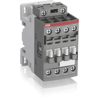
1SBX404551R1400 ABB: The AF16-80-00-14LU is a 8-pole - 600 UL contactor set with screw terminals, dedicated for UL lighting applications. Thanks to the AF technology, the contactor has a wide control voltage range (250-500 V 50/60 Hz and DC), managing large control voltage variations, reducing panel energy consumptions and ensuring distinct operations in unstable networks. Furthermore, surge protection is built-in, offering a compact solution. AF contactors have a block type design, can be easily extended with add-on auxiliary contact blocks and an additional wide range of accessories.
Minimum Order Quantity
1 piece
Data Sheet, Technical Information
1SBC100214C0202 - Main catalog Motor protection and control Manual motor starters, contactors and overload relays (PDF) - Edition 2024
Instructions and Manuals
Installation instructions AF(C)09...38(Z)(B) Contactors, NF(C)(Z)(B)22...80E Contactor relays and CA4, CAL4, CAT4, CC4, LDC4 Accessories
Instructions and Manuals (Part 2)
Contactors and Overload relays guide
CAD Dimensional Drawing
Information - 2D and 3D files for CAD systems
Product Net Width
90 mm
Product Net Depth / Length
77 mm
Product Net Height
86 mm
Product Net Weight
0.62 kg
Number of Main Contacts NO
8
Number of Main Contacts NC
0
Number of Auxiliary Contacts NO
0
Number of Auxiliary Contacts NC
0
Number of Poles
8P
Standards
IEC/EN 60947-1, IEC/EN 60947-4-1, UL 60335-2-40 LZGH2 A2L, UL 508, CSA C22.2 No. 60335-2-40 LZGH2 A2L, CSA C22.2 No. 60947-4-1
Rated Operational Voltage
Main Circuit 690 V
Rated Frequency (f)
Control Circuit 50 / 60 Hz | Main Circuit 50 / 60 Hz
Conventional Free-air Thermal Current (Ith)
acc. to IEC 60947-4-1, Open Contactors Θ = 40 °C 35 A
Rated Operational Current AC-1 (Ie)
(690 V) 40 °C 30 A | (690 V) 60 °C 30 A | (690 V) 70 °C 26 A
Rated Operational Current AC-3 (Ie)
(415 V) 60 °C 18 A | (440 V) 60 °C 18 A | (500 V) 60 °C 15 A | (690 V) 60 °C 10.5 A | (380 / 400 V) 60 °C 18 A | (220 / 230 / 240 V) 60 °C 18 A
Rated Operational Power AC-3 (Pe)
(400 V) 7.5 kW | (415 V) 9 kW | (440 V) 9 kW | (500 V) 9 kW | (690 V) 9 kW | (380 / 400 V) 7.5 kW | (220 / 230 / 240 V) 4 kW
Rated Short-time Withstand Current Low Voltage (Icw)
at 40 °C Ambient Temp, in Free Air, from a Cold State 10 s 150 A | at 40 °C Ambient Temp, in Free Air, from a Cold State 15 min 35 A | at 40 °C Ambient Temp, in Free Air, from a Cold State 1 min 60 A | at 40 °C Ambient Temp, in Free Air, from a Cold State 1 s 300 A | at 40 °C Ambient Temp, in Free Air, from a Cold State 30 s 80 A
Maximum Breaking Capacity
cos phi=0.45 (cos phi=0.35 for Ie > 100 A) at 440 V 250 A | cos phi=0.45 (cos phi=0.35 for Ie > 100 A) at 690 V 106 A
Rated Insulation Voltage (Ui)
acc. to IEC 60947-4-1 690 V | acc. to UL/CSA 600 V
Rated Impulse Withstand Voltage (Uimp)
6 kV
Maximum Electrical Switching Frequency
(AC-1) 600 cycles per hour
Maximum Mechanical Switching Frequency
3600 cycles per hour
Rated Control Circuit Voltage (Uc)
50 Hz 250 ... 500 V | 60 Hz 250 ... 500 V | DC Operation 250 ... 500 V
Power Loss
at Rated Operating Conditions AC-1 per Pole 1.2 W | at Rated Operating Conditions AC-3 per Pole 0.35 W
Operate Time
Between Coil De-energization and NC Contact Closing 13 ... 98 ms | Between Coil De-energization and NO Contact Opening 11 ... 95 ms | Between Coil Energization and NC Contact Opening 38 ... 90 ms | Between Coil Energization and NO Contact Closing 40 ... 95 ms
Mounting on DIN Rail
TH35-15 (35 x 15 mm Mounting Rail) acc. to IEC 60715 | TH35-7.5 (35 x 7.5 mm Mounting Rail) acc. to IEC 60715
Mounting by Screws (not supplied)
2 x M4 screws placed diagonally
Connecting Capacity Main Circuit
Flexible with Ferrule 1/2x 0.75 ... 6 mm² | Flexible with Insulated Ferrule 1x 0.75 ... 4 mm² | Flexible with Insulated Ferrule 2x 0.75 ... 2.5 mm² | Rigid Solid 1/2x 1 ... 4 mm² | Rigid Stranded 1/2x 1 ... 6 mm²
Connecting Capacity Auxiliary Circuit
Flexible with Ferrule 1/2x 0.75 ... 2.5 mm² | Flexible with Insulated Ferrule 2x 0.75 ... 1.5 mm² | Flexible with Insulated Ferrule 1/2x 0.75 ... 1.5 mm² | Rigid Solid 1/2x 1 ... 2.5 mm² | Rigid Stranded 1/2x 1 ... 2.5 mm²
Connecting Capacity Control Circuit
Flexible with Ferrule 1/2x 0.75 ... 2.5 mm² | Flexible with Insulated Ferrule 1x 0.75 ... 2.5 mm² | Flexible with Insulated Ferrule 2x 0.75 ... 1.5 mm² | Rigid Solid 1/2x 1 ... 2.5 mm² | Rigid Stranded 1/2x 1 ... 2.5 mm²
Wire Stripping Length
Control Circuit 10 mm | Main Circuit 10 mm
Degree of Protection
acc. to IEC 60529, IEC 60947-1, EN 60529 Coil Terminals IP20 | acc. to IEC 60529, IEC 60947-1, EN 60529 Main Terminals IP20
Tightening Torque
Control Circuit 1.2 N·m | Main Circuit 1.5 N·m
Terminal Type
Screw Terminals
Product Name
Block Contactor
Maximum Operating Voltage UL/CSA
Main Circuit 600 V
General Use Rating UL/CSA
(600 V AC) 30 A
Connecting Capacity Main Circuit UL/CSA
Rigid Solid 1/2x 16-10 AWG | Rigid Stranded 1/2x 16-10 AWG
Connecting Capacity Auxiliary Circuit UL/CSA
Rigid Solid 1/2x 18-14 AWG | Rigid Stranded 1/2x 18-14 AWG
Connecting Capacity Control Circuit UL/CSA
Rigid Solid 1/2x 18-14 AWG | Rigid Stranded 1/2x 18-14 AWG
Tightening Torque UL/CSA
Control Circuit 11 in·lb | Main Circuit 13 in·lb
Ambient Air Temperature
Close to Contactor for Storage -60 ... +80 °C | Near Contactor for Operation in Free Air -40 ... 70 °C
Climatic Withstand
Category B according to IEC 60947-1 Annex Q
Maximum Operating Altitude Permissible
Without Derating 3000 m
Resistance to Shock acc. to IEC 60068-2-27
Closed, Shock Direction: B1 25 g | Open, Shock Direction: B1 5 g | Shock Direction: A 30 g | Shock Direction: B2 15 g | Shock Direction: C1 25 g | Shock Direction: C2 25 g
Resistance to Vibrations
4g Closed Position & 2g Open position 5 ... 300 Hz
Pollution Degree
3
Conflict Minerals Reporting Template (CMRT)
CMRT - Conflict Minerals Reporting Template
REACH Declaration
REACH - Letter of Confirmation for block contactors, contactor relays, installation contactors, mini contactors, mini contactor relays, thermal overload relays, electronic overload relays and related accessories
RoHS Information
RoHS II declaration for block contactors, installation contactors, mini contactors, mini contactor relays, thermal overload relays, electronic overload relays and related accessories
RoHS Status
Following EU Directive 2011/65/EU and Amendment 2015/863 July 22, 2019
Toxic Substances Control Act - TSCA
Toxic Substances Control Act (TSCA) declaration for Contactors
WEEE B2C / B2B
Business To Business
WEEE Category
5. Small Equipment (No External Dimension More Than 50 cm)
A2L Certificate – UL
UL-US A2L LZGH2 Certificate of Compliance AF09 ... AF38 3-pole contactors with screw terminals - UL 60335-2-40 Household and Similar Electrical Appliances - Safety - Part 2-40: Particular Requirements for Electrical Heat Pumps, Air-Conditioners and Dehumidifiers | UL-CA A2L LZGH2 Certificate of Compliance AF09 ... AF38 3-pole contactors with screw terminals - CSA C22.2 No. 60335-2-40 Household and Similar Electrical Appliances - Safety - Part 2-40: Particular Requirements for Electrical Heat Pumps, Air-Conditioners and Dehumidifiers
CB Certificate
CB Certificate AF09, AF12, AF16, AF09(Z)B, AF12(Z)B, AF16(Z)B 3 and 4-pole contactors, AFS09, AFS12, AFS16 safety contactors
Declaration of Conformity - CE
EU Declaration of Conformity AF09..LU ... AF80..LU 3 and 4-pole contactors
Declaration of Conformity - UKCA
UK Declaration of Conformity AF09..LU ... AF80..LU 3 and 4-pole contactors
UL Certificate
UL_20180227_E312527_7_1
Package Level 1 Units
box 1 piece
Package Level 1 Width
87 mm
Package Level 1 Depth / Length
79 mm
Package Level 1 Height
92 mm
Package Level 1 Gross Weight
0.62 kg
Package Level 1 EAN
3471523020863
Package Level 3 Units
1296 piece
Object Classification Code
Q
ETIM 7
EC000066 - Power contactor, AC switching
ETIM 8
EC000066 - Power contactor, AC switching
ETIM 9
EC000066 - Power contactor, AC switching
eClass
V11.0 : 27371003
UNSPSC
39121529
AF technology enables a wide control voltage range of 250–500 V AC and DC operation, reducing the impact of voltage fluctuations on coil performance. Business impact is fewer unplanned trips and more consistent motor start-ups, which translates to higher line uptime in packaging, printing, and material handling applications. This makes it ideal for UL lighting circuits and general purpose motor control in 690 V systems. Built-in surge protection protects the coil and main contacts from transient spikes. The business impact is lower panel component wear and longer service life, decreasing maintenance costs in industrial automation lines and energy-intensive processes. Applications include panel feeders for conveyors, pumps, and fans where supply quality varies. Eight-pole, screw-terminal design provides robust, space-efficient control of multi-motor loads. Impact is simplified wiring, reliable connections, and easier field maintenance. This is advantageous in OEM switchgear and machine control cabinets requiring compact, high-contact-count contactors. Modular block design accepts add-on auxiliary contact blocks and accessories. Impact: scalable control architecture, easier retrofits, and reduced total cost of ownership. Applications include automatic start/stop sequences and safety interlocks in high-volume assembly lines. Comprehensive ratings: main circuit 690 V, control circuit 250–500 V, I_e values, IP20 protection, DIN rail mounting TH35 compatibility, and screw terminals. Impact: engineers can design with confidence, knowing the device tolerates demanding environments while offering straightforward installation and maintenance.
Get a Quick Quote for a ABB 1SBX404551R1400
Chat with us on WhatsApp - fast responses guaranteed
Need to speak with someone? We'll call you back within 2 hours during business hours
Interested in ABB 1SBX404551R1400?
Enquire Now
FAQs
The AF16-80-00-14LU is designed for TH35 DIN rail mounting (TH35-15 or TH35-7.5) and can also be mounted with 2 x M4 screws. It uses screw terminals for both main and control circuits, with recommended tightening torques of 1.5 N·m on the main circuit and 1.2 N·m on the control circuit. This simplifies retrofit in existing cabinets and OEM enclosures.
Rated Operational Current AC-1 is 30 A at 690 V (40 °C and 60 °C variants) and 26–30 A depending on ambient. Rated Operational Current AC-3 is 18 A across multiple voltages, including 415–690 V. The device supports a maximum AC-1 breaking capacity and a controlled switching frequency suitable for typical motor loads in industrial panels.
Yes. It is specifically designed for UL lighting applications and general motor control in industrial panels. It features a wide control voltage range (250–500 V) for robust performance in networks with voltage fluctuations, built-in surge protection, and a modular design compatible with auxiliary blocks to expand control logic as needed.
The AF16-80-00-14LU complies with IEC/EN 60947-1 and IEC/EN 60947-4-1, UL 60335-2-40, UL 508, and CSA C22.2 No. 60335-2-40, with UL A2L listings for safety appliances. These certifications support global safety compliance, appliance safety, and cross-border installation in commercial and industrial environments.
AF technology provides a wide control voltage window that tolerates mains variations, reducing nuisance trips and energy waste. The built-in surge protection lowers component wear, while the modular design enables easy retrofits with auxiliary blocks. Together, these features reduce downtime, extend service life, and lower total cost of ownership in automated production lines.